Table of Contents
Quick Links
Table of Contents

Related Manuals for AMGO HS-10


Summary of Contents for AMGO HS-10
- Page 1 TWO POST LIFT Model: HS-10 HS-10H...
-
Page 2: Table Of Contents
CONTENTS Product Features and Specifications ...........1 Installation Requirement ..............4 Steps of Installation ................9 Exploded View ................29 Test Run ..................32 Operation Instruction ..............33 Maintenance .................34 Trouble Shooting ................35 Parts List ..................36 Safe Tips..................39... -
Page 3: Product Features And Specifications
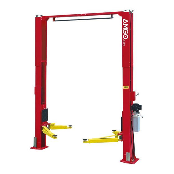
. Clear-floor design, provide unobstructed floor use . Overhead safety shut-off device prevents vehicle damage . Standard adjustable heights accommodates varying ceiling heights · Super-asymmetric arms design can fit extremely wide vehicles. Fig. 1 MODEL HS-10 HS-10H SPECIFICATIONS Width Lifting Lifting Lifting... - Page 4 Arm Swings View for Model HS-10 and HS-10H Fig. 2 Attention: front arm array when car in Fig. 3...
- Page 5 Supporting point of lifting arm spread after car in Fig. 4...
-
Page 6: Installation Requirement
II. INSTALLATION REQUIREMENT A. TOOLS REQUIRED Rotary Hammer Drill (3/4”) Carpenter’s Chalk Hammer Screw Sets Level Bar Tape Measure (295”) English Spanner (12") Pliers Ratchet Spanner With Socket (28 Socket Head Wrench (3 ... - Page 7 Check and ensure the installation location (concrete, layout, space size etc.) is suitable for lift installation. B. Use a carpenter’s chalk line to establish installation layout of base-plate (See Fig. 7). HS-10/HS-10H installation diagram Chalk Line 137- 1/2” Fig. 7...
-
Page 8: Move The Lift Aside With A Fork Lift Or Hoist, And Open The Outer Packing Carefully And
C. Check the parts before assembly. 1. Packaged lift and hydraulic power unit ( See Fig. 8). Fig. 8 2. Move the lift aside with a fork lift or hoist, and open the outer packing carefully and remove aside the top connecting assy. and parts box (See Fig. - Page 9 4. Lift the lower column with a fork lift or hoist, take down the package stand, than take off the lower extension column, take out the parts in the inner column (See Fig. 11). Raise up the lift by forklift truck Remove package Fig.
- Page 10 Check the parts of the parts bag 2 according to parts bag list (See Fig. 15). Fig. 15 Fig. 15 Check the parts of the parts bag 3 according to parts bag list (See Fig. 16). Fig. 16 D. Install parts of extension columns (See Fig. 17). Fig.
- Page 11 E. Install hydraulic cylinder Warp the tape to both side of straight fitting and connecting it with 90° fitting, then install the cylinder into the carriages (See Fig. 18). Offside column Powerside column Put the cylinder into Connect the fitting column which wrap in order with tape and...
- Page 12 This lift is designed with 2-section columns. Adjustable height according to the ceiling height and connecting the inner and extension columns. For model HS-10 1. When the ceiling height is over 147-5/8”, connecting the extension columns with the lower holes (See Fig. 19) Fig. 19 High Setting (HS-10)
- Page 13 2. When the ceiling height is lower than 147-5/8”, connecting the extension columns with the upper holes (See Fig.20) Fig. 20 Low Setting (HS-10)
- Page 14 For model HS-10H 1. When the ceiling height is over 171-1/4”, connecting the extension columns with the lower holes (See Fig. 21) Fig. 21 High Setting(HS-10H)
- Page 15 2. When the ceiling height is over 167-1/4” but lower than 171-1/4”, connecting the extension columns with the middle holes (See Fig.22) Fig. 22 Median Setting(HS-10H)
- Page 16 3. When the ceiling height is lower than 167-1/4”, connecting the extension columns with the upper holes. (See Fig.23) Fig. 23 Low Setting(HS-10H)
- Page 17 G. Position columns Position the columns on the installation layout of base plate. Check the columns vertical with level bar, and adjusting with the shims if the columns are not vertical. Do not tighten the anchor bolts (See Fig.24) Width between columns:110-1/4”...
- Page 18 H. Install overhead top beam 1. With help of the hook of top beam, put one side of top beam on top of the extension column and connecting the top beam to extension column by bolts, tighten the bolts. Then assemble the connecting bracket (See Fig.
- Page 19 2. Assemble overhead top beam, tighten the columns anchor bolts (See Fig. 26) Tighten Tighten the anchor bolts with ratchet spanner with socket Fig. 26 Torque of tighten the anchor bolts is 150N.m.
- Page 20 I. Installing the limit switch control bar and limit switch (See Fig. 27). Loosen screw of drive rod for adjustment, tighten the screw after adjustment Connect the blue wire to Limit switch terminal 11# on limit switch connected and terminal A1 on AC with cable contactor of power unit Connect the brown wire...
- Page 21 J. Install safety device (See Fig. 28 & Fig. 29 Fig. 28 Powerside safety device Fig. 29 Offside safety device...
- Page 22 K. Raise the carriages up by hand and make them be locked at the same level (See Fig. 30). Fig. 30...
- Page 23 L. Install power unit (See Fig. 31) Fig. 31...
- Page 24 I. Install oil hose (See Fig. 32) Oil hose and wire pass through the support bracket Oil hose pass through the retainer on top beam Straight fitting connect with oil hose Fig. 32...
- Page 25 J. Install safety cable. Install safety cable from offside safety assy. firstly, pass through the top beam, then install to power side safety assy. (See Fig. 33) Safety cable pass through Safety cable small pulley bracket Install safety cable from offside safety assy.
- Page 26 K. Install retainer (See Fig. 34). Fix the oil hose with retainer Car in direction Fix the oil hose with retainer Fig. 34...
- Page 27 L. Install lifting arms and adjust the arm locks 1. Install lifting arms (See Fig. 35) 2. Lowing the carriages down to the lowest position, then use the socket head wrench to loosen the socket bolt (See Fig.36) 3. Adjust moon gear as direction of arrow (See Fig.37) 4.
- Page 28 M. Install electrical system Connect the power source on the data plate of Power Unit. Note: 1. For the safety of operators, the earth wire must contact the floor well. 2. Pay attention to the direction of rotations when using three phase motors. Single phase motor (See Fig.
-
Page 29: Exploded View
IV. EXPLODED VIEW Model HS-10, HS-10H Fig. 42... - Page 30 50-2 50-4 50-1 50-5 50-6 Main Cylinder 50-13 50-3 50-9 50-7 50-14 50-10 50-12 Fig. 43 50-8 50-11 50-15 Secondary cylinder 50A -2 50A-1 50A -2A 50A -3 50A-9 50A -10 50A -8 50A -4 50A -5 50A -11 50A -7 50A -6 Fig.
-
Page 31: Test Run
Fig. 45 Illustration of hydraulic valve for hydraulic power unit (220V/60HZ/1PH, manual, Fig.46) Oil return port Relief valve Release valve Throttle valve Oil Outlet Handle for Release valve port Check valve Fig. 46 V. TEST RUN 1. Adjust safety cable... - Page 32 Lifting the carriages and lock at the same height, strain the safety cable and then release a little, and then tighten the cable nuts. Make sure the safety device can always be worked properly. 2. Synchronization The Synchronization adopts hydraulic equalization system. Fig.
-
Page 33: Operation Instruction
throttle valve, and then turn the throttle valve clockwise to decrease the lower speed, or counterclockwise to increase the lower speed. Do not forget to tighten the fixing nut after the lower speed adjustment has been done. Fixing Nut Throttle Valve Throttle Valve Fixing Nut Fig. -
Page 34: Maintenance
To lift vehicle 1. Keep clean of site around the lift 2. Position lifting arms to the lowest position 3. Shorten the arms to the shortest condition 4. Open the lifting arms to allow vehicle drive in Position vehicle between columns 6. -
Page 35: Trouble Shooting
3. Safety cable broken 3. replace 4. Oil system is jammed 4. Clean the oil system 5. Hydraulic solenoid valve out of work 5. Repair or replace IX. Parts list for model HS-10 and HS-10H Item Part# Description Qty. Note... - Page 36 HS-10H HS-10 11217237 Power side inner column 071102 Power unit 10209003 Hex bolt 10209033 Lock washer 10217002 Hex nut 11217003 Powerside lock cover 11217004 Main cam lock 10217069 Socket bolt 10206006 Lock washer 10206023 Self locking nut 10420018 Self locking nut...
- Page 37 Limit Bar Bracket 10420026 Lock washer 10206023B Hex Nut 10217005 Plastic Ball 11217006 Lock Release Handle 11217007 Large Spacer 10217030 Spring 11217009 Safety Lock 10217010 Hex bolt 10217011 Hex nut 11217012 Small Spacer Qty. Item Part# Description Note HS-10H HS-10...
- Page 38 Tools tray 10209034 Washer Parts For Hydraulic Main Cylinder 11217301 50-1 Head Cap 10410087 50-2 Y ring 10217298 50-3 Dust Ring 11217304 50-4 Head cap seal kit 10217299 50-5 Y ring USI Item Part# Description HS-10 HS-10H 10217297 50-6 Support Ring...
- Page 39 11217313 50A-9 Bore weldment 11217303 50A-10 Piston rod 10206071 50A-11 Parts For Power unit 220V,60Hz parts list Item Part# Description HS-10 HS-10H Note 81400180 Rubber gasket 81400130 Start capacitor 81400088 Run capacitor 10420148 Cup head bolt with washer 81400066 Cover for capacitor...
- Page 40 81400365 O Ring 10209152 Tie kit 81400267 Magnet 81400290 Filter 81400413 Motor 10420070 Push button 41030055 AC contactor 81400287 Cover of Motor terminal box 71111104 Label 81400296 81400459 Core for Throttle valve 10209069 O Ring 81400266 Relief valve 81400284 Hex iron plug 10720118 Hair pin 10720121...
- Page 41 AMGO HYDRAULIC CORPORATION 1931 Jo Rogers Blvd, Manning, South Carolina, USA Zip: 29102 Tel: (803) 505-6410 Fax: (803) 505-6410 Manual Part No.: 72127204 Revision Date: 09/2018...