
Related Manuals for Emerson ROSEMOUNT 5081-A


Summary of Contents for Emerson ROSEMOUNT 5081-A
- Page 1 Instruction Manual LIQ_MAN_5081A-FF/rev.M January 2015 5081 A Fieldbus two-Wire Chlorine, ouNdAtIoN ™ dissolved oxygen, and ozone transmitter...
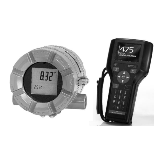
- Page 2 If a 375 or 475 universal Communicator is used with these transmitters, the software within the 375 or 475 may require modification. If a software modification is required, please contact your local Emerson Process Management Service Group or National Response Center at 1-800-654-7768.
-
Page 3: Table Of Contents
MODEL 5081-A TABLE OF CONTENTS 5081-A MICROPROCESSOR TRANSMITTER TABLE OF CONTENTS Section Title Page DESCRIPTION AND SPECIFICATIONS ..............Features and Applications..................Specifications - General................... Specifications - oxygen ................... Specifications - Free Chlorine.................. Specifications - pH ....................Specifications - total Chlorine.................. Specifications - ozone ..................... -
Page 4: Section Title
MODEL 5081-A TABLE OF CONTENTS TABLE OF CONTENTS CONT’D Section Title Page PROGRAMMING..................... General ........................default Settings......................temperature Settings....................display ........................Calibration Setup..................... Line Frequency ......................pH Measurement ..................... Barometric Pressure ....................CALIBRATION — TEMPERATURE................ Introduction ......................Procedure using the infrared remote controller............Procedure using deltaV ................... - Page 5 MODEL 5081-A TABLE OF CONTENTS TABLE OF CONTENTS CONT’D Section Title Page 13.0 CALIBRATION — pH ....................13.1 Introduction ......................13.2 Procedure — Auto Calibration using the infrared remote controller......13.3 Procedure — Auto Calibration using deltaV ............13.4 Procedure — Manual Calibration using the infrared remote controller ....13.5 Procedure —...
- Page 6 MODEL 5081-A TABLE OF CONTENTS LIST OF FIGURES Number Title Page transmitter display during Calibration and Programming............Infrared Remote Controller ..................... Functional Block diagram for the Model 5081-A-FF transmitter..........Asset Management Solutions (AMS) Configuration Screen ........... Asset Management Solutions (AMS) Measurement Screen ..........Model 5081-A Mounting and dimensional drawings ..............
-
Page 7: Description And Specifications
MODEL 5081-A SECTION 1.0 DESCRIPTION AND SPECIFICATIONS SECTION 1.0 DESCRIPTION AND SPECIFICATIONS • MEASuRES dissolved oxygen (ppm and ppb level), free chlo- rine, total chlorine, and ozone. • SECoNd INPut FoR pH SENSoR ALLoWS AutoMAtIC pH CoRRECtIoN for free chlorine measurement. No expensive reagents needed. -
Page 8: Specifications - General
MODEL 5081-A SECTION 1.0 DESCRIPTION AND SPECIFICATIONS 1.2 SPECIFICATIONS - GENERAL ATEx 0600 II 1 G Baseefa02AtEX1284 Housing: Cast aluminum with epoxy coating. EEx ia IIC t4 type 4X (IP65). Neoprene o-ring cover seals. tamb = -20°C to +65°C Dimensions: 160.5 mm x 175.3 mm x 161.3 mm (6.3 IECEx BAS 09.0159X in. -
Page 9: Specifications - Oxygen
MODEL 5081-A SECTION 1.0 DESCRIPTION AND SPECIFICATIONS 1.3 SPECIFICATIONS OxyGEN 1.6 SPECIFICATIONS — TOTAL CHLORINE — Measurement Range: 0-99 ppm (mg/L), 0-200% satura- Measurement Range: 0-20 ppm (mg/L) as Cl tion Resolution: 0.001 ppm (Autoranges at 0.999 to 1.00 and Resolution: 0.01 ppm, 0.1 ppb for 499A trdo sensor 9.99 to 10.0) Temperature correction for membrane permeability:... -
Page 10: Transmitter Display During Calibration And Programming
MODEL 5081-A SECTION 1.0 DESCRIPTION AND SPECIFICATIONS 1.8 TRANSMITTER DISPLAy DURING CALI- BRATION AND PROGRAMMING (Figure 1-1) 1. Continuous display of oxygen, chlorine, or ozone read- ing. 2. units: ppm, ppb, or % saturation. 3. Current menu appears here. 4. Submenus, prompts, and diagnostic readings appear hear. -
Page 11: Oundation Fieldbus
MODEL 5081-A SECTION 1.0 DESCRIPTION AND SPECIFICATIONS 1.10 F FIELDBUS (FIGURE 1-3) OUNDATION Figure 1-3 is the block diagram for the 5081-A-FF transmitter. AMS Inside from Rosemount Analytical allows plant per- sonnel to read process variables and completely configure F Fieldbus transmitters. -
Page 12: Asset Management Solutions (Ams)
MODEL 5081-A SECTION 1.0 DESCRIPTION AND SPECIFICATIONS 1.12 ASSET MANAGEMENT SOLUTIONS (AMS) (FIGURE 1-4) Rosemount Analytical AMS windows provide access to all transmitter measurement and configuration variables. the user can read raw data, final data, and program settings and can reconfigure the transmitter from anywhere in the plant. Figures 1-4 and 1-5 show two of the many configuration and measurement screens available. -
Page 13: Model 5081-A Mounting And Dimensional Drawings
MODEL 5081-A SECTION 1.0 DESCRIPTION AND SPECIFICATIONS MILLIMETER INCH FIGURE 1-6. MODEL 5081-A MOUNTING AND DIMENSIONAL DRAWINGS... -
Page 14: Ordering Information
MODEL 5081-A SECTION 1.0 DESCRIPTION AND SPECIFICATIONS 1.13 ORDERING INFORMATION the Model 5081-A Transmitter is intended for the determination of oxygen (ppm and ppb level), free chlorine, total chlorine, and ozone. For free chlorine measurements, which often require continuous pH correction, a sec- ond input for a pH sensor is available. -
Page 15: Installation
MODEL 5081-A SECTION 2.0 INSTALLATION SECTION 2.0 INSTALLATION 2.1 Unpacking and inspection 2.2 Orienting the display board 2.3 Installation 2.4 Power supply wiring 2.1 UNPACKING AND INSPECTION Inspect the shipping container. If it is damaged, contact the shipper immediately for instructions. Save the box. If there is no apparent damage, remove the transmitter. -
Page 16: Mounting The Model 5081-A On A Flat Surface
MODEL 5081-A SECTION 2.0 INSTALLATION 2.3.2 Mounting on a flat surface. MILLIMETER INCH FIGURE 2-1. Mounting the Model 5081-A on a flat surface... - Page 17 MODEL 5081-A SECTION 2.0 INSTALLATION 2.3.3 Pipe Mounting. MILLIMETER INCH dWG. No. REV. 40508104 dWG. No. REV. 40508103 FIGURE 2-2. Using the pipe mounting kit (PN 2002577) to attach the Model 5081-A to a pipe.
-
Page 18: Power Supply Wiring
MODEL 5081-A SECTION 2.0 INSTALLATION 2.4 POWER SUPPLy WIRING Refer to Figures 2-3 and 2-4. Run the power/signal wiring through the opening nearest terminals 15 and 16. use shielded cable and ground the shield at the power supply. to ground the transmitter, attach the shield to the grounding screw on the inside of the (9 - 32 VdC) -
Page 19: Wiring
MODEL 5081-A SECTION 3.0 SENSOR WIRING SECTION 3.0 SENSOR WIRING Wiring Model 499A oxygen, chlorine, and ozone sensors Wiring Model 499ACL-01 (free chlorine) and pH sensors Wiring Model Hx438 and Gx448 sensors NOTE The Model 5081-A transmitter leaves the factory configured for use with the Model 499ADO sen- sor (ppm dissolved oxygen). -
Page 20: Wiring Model 499Acl-01 (Free Chlorine) Sensors And Ph Sensors
MODEL 5081-A SECTION 3.0 SENSOR WIRING 3.2 WIRING MODEL 499ACL-01 (Free Chlorine) SENSORS AND pH SENSORS If free chlorine is being measured and the pH of the liquid varies more than 0.2 pH unit, a continuous correction for pH must be applied to the chlorine reading. therefore, a pH sensor must be wired to the transmitter. this section gives wiring diagrams for the pH sensors typically used. -
Page 21: Free Chlorine Sensor With Standard Cable And 399-09-62 Ph Sensor Without Internal
MODEL 5081-A SECTION 3.0 SENSOR WIRING FIGURE 3-6. Free chlorine sensor with optimum FIGURE 3-5. Free chlorine sensor with standard EMI/RFI cable or variopol cable and 399vP-09 pH cable and 399-09-62 pH sensor without internal sensor without internal preamplifier. preamplifier. FIGURE 3-7. -
Page 22: Wiring Model Hx438 And Gx448 Sensors
MODEL 5081-A SECTION 3.0 SENSOR WIRING 3.3 WIRING Hx438 AND Gx448 SENSORS FIGURE 3-9. Hx438 and Gx448 Sensors. -
Page 23: Intrinsically Safe And Explosion Proof Installations
MODEL 5081-A SECTION 4.0 INTRINSICALLy SAFE & ExPLOSION PROOF INSTALLATIONS SECTION 4.0 INTRINSICALLy SAFE & ExPLOSION PROOF INSTALLATIONS 1400212... - Page 24 MODEL 5081-A SECTION 4.0 INTRINSICALLy SAFE & ExPLOSION PROOF INSTALLATIONS...
- Page 25 MODEL 5081-A SECTION 4.0 INTRINSICALLy SAFE & ExPLOSION PROOF INSTALLATIONS...
- Page 26 MODEL 5081-A SECTION 4.0 INTRINSICALLy SAFE & ExPLOSION PROOF INSTALLATIONS...
- Page 27 MODEL 5081-A SECTION 4.0 INTRINSICALLy SAFE & ExPLOSION PROOF INSTALLATIONS...
- Page 28 MODEL 5081-A SECTION 4.0 INTRINSICALLy SAFE & ExPLOSION PROOF INSTALLATIONS 1400198...
- Page 29 MODEL 5081-A SECTION 4.0 INTRINSICALLy SAFE & ExPLOSION PROOF INSTALLATIONS 1400198...
- Page 30 MODEL 5081-A SECTION 4.0 INTRINSICALLy SAFE & ExPLOSION PROOF INSTALLATIONS 9241472-00...
- Page 31 MODEL 5081-A SECTION 4.0 INTRINSICALLy SAFE & ExPLOSION PROOF INSTALLATIONS 1400294...
- Page 32 MODEL 5081-A SECTION 4.0 INTRINSICALLy SAFE & ExPLOSION PROOF INSTALLATIONS 1400294...
- Page 33 MODEL 5081-A SECTION 4.0 INTRINSICALLy SAFE & ExPLOSION PROOF INSTALLATIONS 9241472-01...
- Page 34 MODEL 5081-A SECTION 4.0 INTRINSICALLy SAFE & ExPLOSION PROOF INSTALLATIONS 1400292...
- Page 35 MODEL 5081-A SECTION 4.0 INTRINSICALLy SAFE & ExPLOSION PROOF INSTALLATIONS 1400292...
-
Page 37: Display And Operation With Infrared Remote Controller
MODEL 5081-A SECTION 5.0 DISPLAy AND OPERATION WITH INFRARED REMOTE CONTROLLER SECTION 5.0 DISPLAy AND OPERATION WITH INFRARED REMOTE CONTROLLER Display Screens Infrared Remote Controller (IRC) - Key Functions Menu Tree Diagnostic Messages Security Using Hold 5.1 DISPLAy SCREENS Figure 5-1 shows the process display screen. Figure 5-2 shows the program display screen. Concentration of oxygen, ozone, or chlorine transmitter output signal in... - Page 38 MODEL 5081-A SECTION 5.0 DISPLAy AND OPERATION WITH INFRARED REMOTE CONTROLLER 5.2 INFRARED REMOTE CONTROLLER (IRC) - KEy FUNCTIONS the infrared remote controller is used to calibrate and program the transmitter and to display diagnostic mes- sages. See Figure 5-3 for a description of the function of the keys. Hold the IRC within 6 feet of the transmitter, and not more than 15 degrees from the center of the display window.
-
Page 39: Menu Tree
MODEL 5081-A SECTION 5.0 DISPLAy AND OPERATION WITH INFRARED REMOTE CONTROLLER 5.3 MENU TREE the Model 5081-A transmitter has three menus: CALIBRAtE, PRoGRAM, and dIAGNoSE. under the Calibrate and Program menus are several submenus. under each submenu are a number of prompts. the dIAGNoSE menu shows the reader diagnostic variables that are useful in troubleshooting. -
Page 40: Menu Tree
MODEL 5081-A SECTION 5.0 DISPLAy AND OPERATION WITH INFRARED REMOTE CONTROLLER FIGURE 5-4. Menu Tree... -
Page 41: Operation With Foundation Fieldbus And The Deltav Control System
MODEL 5081-A SECTION 6.0 OPERATION WITH FOUNDATION FIELDBUS AND THE DELTAv CONTROL SySTEM SECTION 6.0 Operation with F Fieldbus OUNDATION and the Deltav Control System 6.1 OvERvIEW this section covers basic transmitter operation and software functionality. For detailed descriptions of the func- tion blocks common to all Fieldbus devices, refer to Fisher-Rosemount Fieldbus ouNdAtIoN Function Blocks manual, publication number 00809-4783. -
Page 42: Ai Block Configuration
MODEL 5081-A SECTION 6.0 OPERATION WITH FOUNDATION FIELDBUS AND THE DELTAv CONTROL SySTEM 6.2 AI Block Configuration the 5081A-FF has channels assignable to the measured value (oxygen, ozone, or chlorine), temperature, sensor current, and pH (free chlorine only). For proper operation, the AI Block must be assigned to the channel corresponding to the desired measure- ment, and the units in the Xd_SCALE parameter of the AI Block must match the units of the measurement. -
Page 43: Transducer Block Operations - Configuration And Calibration
MODEL 5081-A SECTION 6.0 OPERATION WITH FOUNDATION FIELDBUS AND THE DELTAv CONTROL SySTEM 6.3 Transducer Block Operations — Configuration and Calibration 6.3.1 Deltav Explorer Transducer Block Interface 1. Context Menu the deltaV Explorer exposes methods for changing the process variable, zeroing and standardizing the sensors, calibrating oxygen sensors in air, standardizing the temperature measurement, and standardizing and buffer calibrating the pH sensor (free chlorine only). -
Page 44: Model 5081-A-Ff - Device Summary
MODEL 5081-A SECTION 6.0 OPERATION WITH FOUNDATION FIELDBUS AND THE DELTAv CONTROL SySTEM 3. transducer Block Status the transducer Block Status Windows show all of the diagnostic faults, warnings, and errors. the meaning of these diagnostic messages and troubleshooting procedures for them can be found in the troubleshooting section of this manual. -
Page 45: Model 5081-A-Ff Parameters And Methods
MODEL 5081-A SECTION 6.0 OPERATION WITH FOUNDATION FIELDBUS AND THE DELTAv CONTROL SySTEM TABLE 6-2. Model 5081-A-FF Parameters and Methods Table 6-2 continued on following page. - Page 46 MODEL 5081-A SECTION 6.0 OPERATION WITH FOUNDATION FIELDBUS AND THE DELTAv CONTROL SySTEM TABLE 6-2. Model 5081-A-FF Parameters and Methods (continued) Table 6-2 continued on following page.
- Page 47 MODEL 5081-A SECTION 6.0 OPERATION WITH FOUNDATION FIELDBUS AND THE DELTAv CONTROL SySTEM TABLE 6-2. Model 5081-A-FF Parameters and Methods (continued)
-
Page 48: Programming
MODEL 5081-A SECTION 7.0 PROGRAMMING SECTION 7.0 PROGRAMMING General Default Settings Temperature Settings Display Calibration Setup Line Frequency pH Measurement Barometric Pressure 7.1 GENERAL this section describes how to do the following: 1. enable and disable automatic temperature correction 2. program the type measurement (oxygen, ozone, or chlorine) 3. - Page 49 MODEL 5081-A SECTION 7.0 PROGRAMMING TABLE 7-1. Default Settings ITEM MNEMONIC CHOICES DEFAULT A. Temperature compensation tEMP 1. Automatic tAUtO on or off 2. Manual tMAn -25.0 to 150°C 25°C B. Display dISPLAy 1. type of measurement tyPE oxygen, ozone, free chlorine, total chlorine oxygen 2.
- Page 50 MODEL 5081-A SECTION 7.0 PROGRAMMING 7.3 TEMPERATURE SETTINGS 7.3.1 Purpose this section describes how to do the following: 1. Enable and disable automatic temperature compensation 2. Set a manual temperature compensation value for oxygen, chlorine, ozone, and pH measurements 3. tell the transmitter the type of temperature element in the sensor 7.3.2 Definitions 1.
- Page 51 MODEL 5081-A SECTION 7.0 PROGRAMMING 7.3.3 Procedure using the infrared remote controller 1. Press PRoG on the remote controller. PRoGRAM tEMP 2. Press NEXt until the tEMP submenu appears. Press ENtER. EXIt NEXt ENtER PRoGRAM 3. the screen displays the tAUtO (automatic temperature compensation) prompt. tAUtO Press é...
-
Page 52: Display
MODEL 5081-A SECTION 7.0 PROGRAMMING 7.4 DISPLAy 7.4.1 Purpose this section describes how to do the following: 1. Configure the transmitter to measure oxygen, free chlorine, total chlorine, or ozone 2. Choose concentration units 3. Set the temperature units to °C or °F 4. - Page 53 MODEL 5081-A SECTION 7.0 PROGRAMMING 6. For best results make the following settings based on the sensor being used. Sensor Units 499Ado ppm or % 499Atrdo Gx448 ppm or % Hx438 ppm or % PRoGRAM 7. If you chose O3 in step 3, the screen at left appears. Press é or ê to toggle between Unit ppm and ppb.
-
Page 54: Calibration Setup
MODEL 5081-A SECTION 7.0 PROGRAMMING 7.5 CALIBRATION SETUP 7.5.1 Purpose this section describes how to do the following: 1. Enter stabilization criteria for calibration 2. Enter an upper limit for sensor zero 3. Enter a salinity value for air calibration of dissolved oxygen sensors 4. - Page 55 MODEL 5081-A SECTION 7.0 PROGRAMMING 6. Set the stabilization range to between 0.01 and 9.99 ppm. the default values are PRoGRAM shown in the table. Press ENtER to save. delta . 05 oxygen 0.05 ppm or 1% EXIt ENtER Free chlorine 0.05 ppm total chlorine 0.05 ppm...
- Page 56 MODEL 5081-A SECTION 7.0 PROGRAMMING 7.5.4 Procedure using Deltav Access: deltaV Explorer/transducer Block/Properties, Amperometric Sensor tab 1. Parameter: Amperometric Stabilize time (AMP_SPAN_StABILIZE_tIME) Set the stabilization time between 0 and 99 seconds. the default value is 10 seconds. 2. Parameter: Amperometric Stabilize Value (AMP_SPAN_StABILIZE_VALuE) Set the stabilization range to between 0.01 and 9.99 ppm.
-
Page 57: Line Frequency
MODEL 5081-A SECTION 7.0 PROGRAMMING 7.6 LINE FREQUENCy 7.6.1 Purpose this section describes how to maximize noise rejection by entering the frequency of the mains power into the transmitter. 7.6.2 Procedure using the infrared remote controller. 1. Press PRoG on the remote controller. PRoGRAM 2. -
Page 58: Ph Measurement
MODEL 5081-A SECTION 7.0 PROGRAMMING 7.7 pH MEASUREMENT NOTE The pH measurement submenu appears only if the transmitter has been configured to measure free chlorine. pH is not available with any other measurement. 7.7.1 Purpose this section describes how to do the following: 1. - Page 59 MODEL 5081-A SECTION 7.0 PROGRAMMING 7.7.3 Procedure using the infrared remote controller 1. Press PRoG on the remote controller. PRoGRAM 2. Press NEXt until the PH submenu appears. On will be flashing, indicating that the pH measurement and automatic pH correction of free chlorine has been enabled. EXIt NEXt ENtER...
- Page 60 MODEL 5081-A SECTION 7.0 PROGRAMMING PRoGRAM 10. once diagnostic limits have been set, the display returns to the dIAgnOStIC sub- dIagnostIC menu header. Press NEXt. EXIt NEXt ENtER 11. the PH CAL submenu header appears. Prompts under this header allow the user to PRoGRAM enable or disable automatic buffer calibration, select the buffers to be used, and set PH Cal...
- Page 61 MODEL 5081-A SECTION 7.0 PROGRAMMING 7.7.4 Procedure using Deltav Access: deltaV Explorer/transducer Block/Properties, pH Compensation tab 1. pH Compensation (Auto/Manual) and Preamp Location Parameter: pH Compensation/Preamp Location (PH_CoMPENSAtIoN_ModE) Select the pH compensation mode and preamp location from the following table: Description value Digital Equivalent...
-
Page 62: Barometric Pressure
MODEL 5081-A SECTION 7.0 PROGRAMMING 7.8 BAROMETRIC PRESSURE NOTE The barometric pressure submenu appears only if the transmitter has been configured to measure oxygen. 7.8.1 Purpose this section describes how to do the following 1. Set the units for barometric pressure 2. - Page 63 MODEL 5081-A SECTION 7.0 PROGRAMMING 7.8.4 Procedure using Deltav Access: deltaV Explorer/transducer Block/Properties, Amperometric Sensor tab 1. Enter the desired barometric pressure units from the following: mm Hg in Hg Parameter: Barometric Pressure unit (BAR_PRESSuRE_uNIt) 2. If % saturation units were selected, enter the desired % saturation pressure. Parameter: Percent Saturation Pressure (PERCENt_SAtuRAtIoN_PRESSuRE)
-
Page 64: Calibration - Temperature
MODEL 5081-A SECTION 8.0 CALIBRATION — TEMPERATURE SECTION 8.0 CALIBRATION — TEMPERATURE 8.1 INTRODUCTION All four amperometric sensors (oxygen, ozone, free chlorine, and total chlorine) are membrane-covered sensors. As the sensor operates, the analyte (the substance to be determined) diffuses through the membrane and is consumed at an electrode immediately behind the membrane. -
Page 65: Procedure Using The Infrared Remote Controller
MODEL 5081-A SECTION 8.0 CALIBRATION — TEMPERATURE 8.2. PROCEDURE USING THE INFRARED REMOTE CONTROLLER 1. Place the sensor and a calibrated reference thermometer in a container of water at ambient temperature. Be sure the temperature element in the sensor is completely submerged by keeping the sensor tip at least three inches below the water level. -
Page 66: Calibration - Oxygen
MODEL 5081-A SECTION 9.0 CALIBRATION — OxyGEN SECTION 9.0 CALIBRATION — OxyGEN 9.1 INTRODUCTION As Figure 9-1 shows, oxygen sensors generate a current directly proportional to the concentration of dissolved oxygen in the sample. Calibrating the sensor requires exposing it to a solution containing no oxygen (zero stan- dard) and to a solution containing a known amount of oxygen (full-scale standard). -
Page 67: Procedure - Zeroing The Sensor Using The Infrared Remote Controller
MODEL 5081-A SECTION 9.0 CALIBRATION — OxyGEN 9.2 PROCEDURE — zEROING THE SENSOR USING THE REMOTE CONTROLLER 1. Place the sensor in a fresh solution of 5% sodium sulfite (Na ) in water. Be sure air bubbles are not trapped against the membrane. the current will drop rapidly at first and then gradually reach a stable zero value. -
Page 68: Procedure - Zeroing The Sensor Using Deltav
MODEL 5081-A SECTION 9.0 CALIBRATION — OxyGEN 9.3 PROCEDURE — zEROING THE SENSOR USING Deltav 1. Place the sensor in a fresh solution of 5% sodium sulfite (Na ) in water. Be sure air bubbles are not trapped against the membrane. the current will drop rapidly at first and then gradually reach a stable zero value. -
Page 69: Procedure - Air Calibration Using The Infrared Remote Controller
MODEL 5081-A SECTION 9.0 CALIBRATION — OxyGEN 9.4 PROCEDURE — AIR CALIBRATION USING THE INFRARED REMOTE CONTROLLER 1. Remove the sensor from the process liquid. use a soft tissue and a stream of water from a wash bottle to clean the membrane. -
Page 70: Procedure - Air Calibration Using Deltav
MODEL 5081-A SECTION 9.0 CALIBRATION — OxyGEN 9.5 PROCEDURE — AIR CALIBRATION USING Deltav 1. Remove the sensor from the process liquid. use a soft tissue and a stream of water from a wash bottle to clean the membrane. Blot dry. the membrane must be dry during air calibration. 2. -
Page 71: Procedure - In-Process Calibration Using The Infrared Remote Controller
MODEL 5081-A SECTION 9.0 CALIBRATION — OxyGEN 9.6 PROCEDURE — IN-PROCESS CALIBRATION USING THE REMOTE CONTROLLER 1. the transmitter and sensor can be calibrated against a standard instrument. For oxygen sensors installed in aeration basins in waste treatment plants, calibration against a second instrument is often preferred. For an accurate calibration be sure that: a. -
Page 72: Procedure - In-Process Calibration Using Deltav
MODEL 5081-A SECTION 9.0 CALIBRATION — OxyGEN 9.7 PROCEDURE — IN-PROCESS CALIBRATION USING Deltav 1. the transmitter and sensor can be calibrated against a standard instrument. For oxygen sensors installed in aeration basins in waste treatment plants, calibration against a second instrument is often preferred. For an accurate calibration be sure that: a. -
Page 73: Calibration - Free Chlorine
MODEL 5081-A SECTION 10.0 CALIBRATION - FREE CHLORINE SECTION 10.0 CALIBRATION — FREE CHLORINE 10.1 INTRODUCTION As Figure 10-1 shows, a free chlorine sensor generates a current directly proportional to the concentration of free chlorine in the sample. Calibrating the sensor requires exposing it to a solution containing no chlorine (zero stan- dard) and to a solution containing a known amount of chlorine (full-scale standard). -
Page 74: Procedure - Zeroing The Sensor Using The Infrared Remote Controller
MODEL 5081-A SECTION 10.0 CALIBRATION - FREE CHLORINE 10.2 PROCEDURE — zEROING THE SENSOR USING THE REMOTE CONTROLLER 1. Place the sensor in the zero standard (see Section 10.1). Be sure no air bubbles are trapped against the mem- brane. the sensor current will drop rapidly at first and then gradually reach a stable zero value. to monitor the sensor current, go to the main display. -
Page 75: Procedure - Zeroing The Sensor Using Deltav
MODEL 5081-A SECTION 10.0 CALIBRATION - FREE CHLORINE 10.3 PROCEDURE — zEROING THE SENSOR USING Deltav 1. Place the sensor in the zero standard (see Section 10.1). Be sure no air bubbles are trapped against the mem- brane. the sensor current will drop rapidly at first and then gradually reach a stable zero value. to monitor the sensor current, go to the main display. -
Page 76: Procedure - Full Scale Calibration Using The Infrared Remote Controller
MODEL 5081-A SECTION 10.0 CALIBRATION - FREE CHLORINE 10.4 PROCEDURE — FULL SCALE CALIBRATION USING THE REMOTE CONTROLLER 1. Place the sensor in the process liquid. If automatic pH correction is being used, calibrate the pH sensor (see Section 13.0) and place it in the process liquid. If manual pH correction is being used, measure the pH of the process liquid and enter the value (see Section 7.8). -
Page 77: Procedure - Full Scale Calibration Using Deltav
MODEL 5081-A SECTION 10.0 CALIBRATION - FREE CHLORINE 10.5 PROCEDURE — FULL SCALE CALIBRATION USING Deltav 1. Place the sensor in the process liquid. If automatic pH correction is being used, calibrate the pH sensor (see Section 13.0) and place it in the process liquid. If manual pH correction is being used, measure the pH of the process liquid and enter the value (see Section 7.8). -
Page 78: Dual Slope Calibration
MODEL 5081-A SECTION 10.0 CALIBRATION - FREE CHLORINE 10.6 DUAL SLOPE CALIBRATION Figure 10-2 show the principle of dual slope calibration. Between zero and concentration C1, the sensor response is linear. When the concentration of chlorine becomes greater than C1, the response is non-linear. In spite of the non-linearity, the response can be approximated by a straight line between point 1 and point 2. - Page 79 MODEL 5081-A SECTION 10.0 CALIBRATION - FREE CHLORINE CALIBRAtE 9. the Pt1 prompt appears. use the arrow keys to change the flashing . 00 display to the concentration of chlorine determined in the grab sample. EXIt ENtER Press ENtER to save. CALIBRAtE 10.
-
Page 81: Calibration - Total Chlorine
MODEL 5081-A SECTION 11.0 CALIBRATION - TOTAL CHLORINE SECTION 11.0 CALIBRATION — TOTAL CHLORINE 11.1 INTRODUCTION total chlorine is the sum of free and combined chlorine. the continuous determination of total chlorine requires two steps. See Figure 11-1. First, the sample flows into a conditioning system (SCS 921) where a pump continuously adds acetic acid and potassium iodide to the sample. - Page 82 MODEL 5081-A SECTION 11.0 CALIBRATION - TOTAL CHLORINE 11.2 PROCEDURE — zEROING THE SENSOR USING THE REMOTE CONTROLLER 1. Complete the startup sequence described in the SCS921 instruction manual. Adjust the sample flow to between 80 and 100 mL/min, and set the sample pressure to between 3 and 5 psig. 2.
-
Page 83: Procedure - Zeroing The Sensor Using Deltav
MODEL 5081-A SECTION 11.0 CALIBRATION - TOTAL CHLORINE 11.3 PROCEDURE — zEROING THE SENSOR USING Deltav 1. Complete the startup sequence described in the SCS921 instruction manual. Adjust the sample flow to between 80 and 100 mL/min, and set the sample pressure to between 3 and 5 psig. 2. -
Page 84: Procedure - Full Scale Calibration Using The Infrared Remote Controller
MODEL 5081-A SECTION 11.0 CALIBRATION - TOTAL CHLORINE 11.4 PROCEDURE — FULL SCALE CALIBRATION USING THE REMOTE CONTROLLER 1. If the sensor was just zeroed, place the reagent uptake tube back in the bottle. once the flow of reagent starts, it takes about one minute for the sensor current to begin to increase. -
Page 85: Procedure - Full Scale Calibration Using Deltav
MODEL 5081-A SECTION 11.0 CALIBRATION - TOTAL CHLORINE 11.5 PROCEDURE — FULL SCALE CALIBRATION USING Deltav 1. If the sensor was just zeroed, place the reagent uptake tube back in the bottle. once the flow of reagent starts, it takes about one minute for the sensor current to begin to increase. It may take an hour or longer for the read- ing to stabilize. -
Page 86: Dual Slope Calibration
MODEL 5081-A SECTION 11.0 CALIBRATION - TOTAL CHLORINE 11.6 DUAL SLOPE CALIBRATION Figure 11-3 show the principle of dual slope calibration. Between zero and concentration C1, the sensor response is linear. When the concentration of chlorine becomes greater than C1, the response is non-linear. In spite of the non-linearity, the response can be approximated by a straight line between point 1 and point 2. - Page 87 MODEL 5081-A SECTION 11.0 CALIBRATION - TOTAL CHLORINE CALIBRAtE 9. the Pt1 prompt appears. use the arrow keys to change the flashing . 00 display to the concentration of chlorine determined in the grab sample. EXIt ENtER Press ENtER to save. CALIBRAtE 10.
-
Page 88: Calibration - Ozone
MODEL 5081-A SECTION 12.0 CALIBRATION - OzONE SECTION 12.0 CALIBRATION — OzONE 12.1 INTRODUCTION As Figure 12-1 shows, an ozone sensor generates a current directly proportional to the concentration of ozone in the sample. Calibrating the sensor requires exposing it to a solution containing no ozone (zero standard) and to a solution containing a known amount of ozone (full-scale standard). - Page 89 MODEL 5081-A SECTION 12.0 CALIBRATION - OzONE 12.2 PROCEDURE — zEROING THE SENSOR USING THE REMOTE CONTROLLER 1. Place the sensor in the zero standard (see Section 12.1). Be sure no air bubbles are trapped against the mem- brane. the sensor current will drop rapidly at first and then gradually reach a stable zero value. to monitor the sensor current, go to the main display.
-
Page 90: Procedure - Zeroing The Sensor Using Deltav
MODEL 5081-A SECTION 12.0 CALIBRATION - OzONE 12.3 PROCEDURE — zEROING THE SENSOR USING Deltav 1. Place the sensor in the zero standard (see Section 12.1). Be sure no air bubbles are trapped against the mem- brane. the sensor current will drop rapidly at first and then gradually reach a stable zero value. to monitor the sensor current, go to the main display. -
Page 91: Procedure - Full Scale Calibration Using Deltav
MODEL 5081-A SECTION 12.0 CALIBRATION - OzONE CALIBRAtE 6. the GrAb SPL (grab sample) prompt appears. take a sample of the Grab spl process liquid and immediately determine the concentration of ozone in the sample. Press ENtER. EXIt ENtER CALIBRAtE 7. -
Page 92: Calibration - Ph
MODEL 5081-A SECTION 13.0 CALIBRATION - pH SECTION 13.0 CALIBRATION — pH 13.1 INTRODUCTION A new pH sensor must be calibrated before use. Regular recalibration is also necessary. A pH measurement cell (pH sensor and the solution to be measured) can be pictured as a battery with an extreme- ly high internal resistance. -
Page 93: Procedure - Auto Calibration Using The Infrared Remote Controller
MODEL 5081-A SECTION 13.0 CALIBRATION - pH 13.2 PROCEDURE — AUTO CALIBRATION USING THE REMOTE CONTROLLER 1. Verify that auto calibration has been enabled. See Section 7.8. 2. obtain two buffer solutions. Ideally, the buffer pH values should bracket the range of pH values to be meas- ured. -
Page 94: Procedure - Auto Calibration Using Deltav
MODEL 5081-A SECTION 13.0 CALIBRATION - pH 13.3 PROCEDURE — AUTO CALIBRATION USING Deltav 1. Verify that auto calibration has been enabled. See Section 7.8. 2. obtain two buffer solutions. Ideally, the buffer pH values should bracket the range of pH values to be meas- ured. -
Page 95: Procedure - Manual Calibration Using The Infrared Remote Controller
MODEL 5081-A SECTION 13.0 CALIBRATION - pH 13.4 PROCEDURE — MANUAL CALIBRATION USING THE REMOTE CONTROLLER 1. Verify that manual calibration has been enabled. See Section 7.8. 2. obtain two buffer solutions. Ideally, the buffer pH values should bracket the range of pH values to be meas- ured. -
Page 96: Procedure - Manual Calibration Using Deltav
MODEL 5081-A SECTION 13.0 CALIBRATION - pH 13.5 PROCEDURE — MANUAL CALIBRATION USING Deltav 1. Verify that manual calibration has been enabled. See Section 7.8. 2. obtain two buffer solutions. Ideally, the buffer pH values should bracket the range of pH values to be meas- ured. -
Page 97: Standardization Using The Infrared Remote Controller
MODEL 5081-A SECTION 13.0 CALIBRATION - pH 13.6 STANDARDIzATION USING THE INFRARED REMOTE CONTROLLER 1. the pH measured by the transmitter can be changed to match the reading from a second or reference instru- ment. the process of making the two readings agree is called standardization, or one-point calibration. 2. -
Page 98: Standardization Using Deltav
MODEL 5081-A SECTION 13.0 CALIBRATION - pH 13.7 STANDARDIzATION USING Deltav 1. the pH measured by the transmitter can be changed to match the reading from a second or reference instru- ment. the process of making the two readings agree is called standardization, or one-point calibration. 2. -
Page 99: Ph Slope Adjustment Using The Infrared Remote Controller
MODEL 5081-A SECTION 13.0 CALIBRATION - pH 13.8 pH SLOPE ADJUSTMENT USING THE INFRARED REMOTE CONTROLLER 1. If the slope of the glass electrode is known form other measurements, it can be entered directly into the trans- mitter. the slope must be entered as the slope at 25°C. to calculate the slope at 25°C from the slope at tem- perature t°C, use the equation: slope at 25°C = (slope at t°C) t°C + 273... -
Page 100: Ph Slope Adjustment Using Deltav
MODEL 5081-A SECTION 13.0 CALIBRATION - pH 13.9 pH SLOPE ADJUSTMENT USING Deltav 1. If the slope of the glass electrode is known form other measurements, it can be entered directly into the trans- mitter. the slope must be entered as the slope at 25°C. to calculate the slope at 25°C from the slope at tem- perature t°C, use the equation: slope at 25°C = (slope at t°C) t°C + 273... -
Page 101: Diagnostics
MODEL 5081-A SECTION 14.0 DIAGNOSTICS SECTION 14.0 DIAGNOSTICS 14.1 GENERAL the 5081-A transmitter can display diagnostic information that is useful in troubleshooting. the diagnostics avail- able depend on the measurement being made. to read diagnostic information, go to the main display and press dIAG on the infrared remote controller. -
Page 102: Diagnostic Messages For Free Chlorine
MODEL 5081-A SECTION 14.0 DIAGNOSTICS 14.4 DIAGNOSTIC MESSAGES FOR FREE CHLORINE TyPE FCL transmitter is measuring free chlorine. Press NEXt to view diagnostics. SEnSor Cur Press ENtER to display raw current from sensor (note units). SEnSitvty Press ENtER to display sensitivity. Sensitivity is calculated during calibration. It is the measured current divided by concentration. -
Page 103: Troubleshooting
MODEL 5081-A SECTION 15.0 TROUBLESHOOTING SECTION 15.0 TROUBLESHOOTING 15.1 WARNING, FAULT, AND ERROR MESSAGES 15.2 TROUBLESHOOTING WHEN A WARNING OR FAULT MESSAGE IS SHOWING 15.3 TEMPERATURE MEASUREMENT AND CALIBRATION PROBLEMS 15.4 OxyGEN MEASUREMENT AND CALIBRATION PROBLEMS 15.5 FREE CHLORINE MEASUREMENT AND CALIBRATION PROBLEMS 15.6 TOTAL CHLORINE MEASUREMENT AND CALIBRATION PROBLEMS 15.7... - Page 104 MODEL 5081-A SECTION 15.0 TROUBLESHOOTING 15.2 TROUBLESHOOTING WHEN A FAULT, WARNING, OR ERROR MESSAGE IS SHOWING Fault Explanation See Section RTD OPEn Rtd measuring circuit is open. 15.2.1 bAd rtd Rtd resistance is outside the range expected for a Pt100 or 22k NtC. 15.2.1 PHgLASS HI pH glass impedance exceeds programmed limit.
- Page 105 MODEL 5081-A SECTION 15.0 TROUBLESHOOTING 15.2.1 RTD OPEn, bAd RTd, tEMP HI, tEMP LO, and SenSE OPEn these messages usually mean that the Rtd (or thermistor in the case of the HX438 and GX448 sensors) is open or short- ed or there is an open or short in the connecting wiring. 1.
- Page 106 MODEL 5081-A SECTION 15.0 TROUBLESHOOTING 15.2.4 OuEr rAngE, In Curr HI, and In Curr LO the first two messages imply that the amperometric sensor current is very high (greater than 210 µA) or the sensor cur- rent has a very large negative number. Normally, excessive current or negative current implies that the amperometric sen- sor is miswired or has failed.
- Page 107 MODEL 5081-A SECTION 15.0 TROUBLESHOOTING 15.2.8 EECHECSUn EE Chksum Error means a software setting changed when it was not supposed to. the EEPRoM may be going bad. Call the factory for assistance. 15.2.9 EEOF EE Buffer Overflow means the software is trying to change too many background variables at once. Remove power from the transmitter for about 30 seconds.
- Page 108 MODEL 5081-A SECTION 15.0 TROUBLESHOOTING 15.2.14 0 OFFSEt the -0- OFFSEt message appears if the standardization offset (in mV) exceeds the programmed limit. the default limit is 60 mV, which is equivalent to about a unit change in pH. Before increasing the limit to make the -0- OFFSEt message dis- appear, check the following: 1.
- Page 109 MODEL 5081-A SECTION 15.0 TROUBLESHOOTING 15.4 OxyGEN MEASUREMENT AND CALIBRATION PROBLEMS Problem See Section Zero current is substantially greater than the value in Section 9.2 15.4.1 Zero reading is unstable 15.4.2 Sensor current during air calibration is substantially different from the value in Section 9.3 15.4.3 Process and standard instrument readings during in-process calibration are substantially different 15.4.4...
- Page 110 MODEL 5081-A SECTION 15.0 TROUBLESHOOTING 15.4.3 Sensor current during air calibration is substantially different from the value in Section 9.3. 1. Is the sensor properly wired to the transmitter? See Section 3.0. Verify that all connections are tight. 2. Is the membrane dry? the membrane must be dry during air calibration. A droplet of water on the membrane during air calibration will lower the sensor current and cause an inaccurate calibration.
- Page 111 MODEL 5081-A SECTION 15.0 TROUBLESHOOTING 15.4.7 Sensor does not respond to changes in oxygen level. If readings are being compared with a portable laboratory instrument, verify that the laboratory instrument is working. Is the membrane clean? Clean the membrane and replace it if necessary. Check that the holes at the base of the cathode stem are open.
- Page 112 MODEL 5081-A SECTION 15.0 TROUBLESHOOTING 15.5.2 zero reading is unstable. 1. Is the sensor properly wired to the transmitter? See Section 3.0. Verify that all wiring connections are tight. 2. Readings are often erratic when a new or rebuilt sensor is first placed in service. Readings usually stabilize after about an hour.
- Page 113 MODEL 5081-A SECTION 15.0 TROUBLESHOOTING 15.5.5 Readings drift. 1. Is the sample temperature changing? Membrane permeability is a function of temperature. the time constant for the 499ACL-01 sensor is about five minutes. therefore, the reading may drift for a while after a sudden temperature change.
- Page 114 MODEL 5081-A SECTION 15.0 TROUBLESHOOTING 15.7 OzONE MEASUREMENT AND CALIBRATION PROBLEMS Problem See Section Zero current is substantially outside the range -10 to 10 nA 15.7.1 Zero reading is unstable 15.7.2 Sensor current during calibration is substantially less than about 350 nA/ppm at 25°C 15.7.3 Process readings are erratic 15.7.4...
- Page 115 MODEL 5081-A SECTION 15.0 TROUBLESHOOTING 15.7.4 Process readings are erratic. 1. Readings are often erratic when a new sensor or a rebuilt sensor is first placed in service. the current usually stabi- lizes after a few hours. 2. Is the sample flow within the recommended range? High sample flow may cause erratic readings. Refer to the sensor instruction sheet for recommended flow rates.
- Page 116 MODEL 5081-A SECTION 15.0 TROUBLESHOOTING 15.8 pH MEASUREMENT AND CALIBRATION PROBLEMS Problem See Section SLoPE HI or SLoPE Lo message is showing 15.8.1 -0- oFFSEt message is showing 15.8.2 transmitter will not accept manual slope 15.8.3 Sensor does not respond to known pH changes 15.8.4 Process pH is slightly different from the expected value 15.8.5...
- Page 117 MODEL 5081-A SECTION 15.0 TROUBLESHOOTING 15.8.7 Process pH is grossly wrong and/or noisy. Grossly wrong or noisy readings suggest a ground loop (measurement system connected to earth ground at more than one point), a floating system (no earth ground), or noise being brought into the transmitter by the sensor cable. the prob- lem arises from the process or installation.
-
Page 118: Simulate Dissolved Oxygen
MODEL 5081-A SECTION 15.0 TROUBLESHOOTING 15.9 SIMULATING INPUT CURRENTS - DISSOLvED OxyGEN to check the performance of the transmitter, use a decade box to simulate the current from the oxygen sensor. A. disconnect the anode and cathode leads from terminals 13 & 14 and connect a decade box as shown in Figure 15-1. It is not necessary to disconnect the Rtd leads. -
Page 119: Simulate Ph
MODEL 5081-A SECTION 15.0 TROUBLESHOOTING 15.11 SIMULATING INPUTS - pH 15.11.1 General this section describes how to simulate a pH input into the transmitter. to simulate a pH measurement, connect a standard millivolt source to the transmitter. If the transmitter is working properly, it will accurately measure the input voltage and con- vert it to pH. -
Page 120: Three-Wire Rtd Configuration
MODEL 5081-A SECTION 15.0 TROUBLESHOOTING 15.12 SIMULATING TEMPERATURE 15.12.1 General the transmitter accepts either a Pt100 Rtd (used in pH, 499Ado, 499Atrdo, 499ACL-01, 499ACL-02, and 499AoZ sensors) or a 22k NtC thermistor (used in HX438 and Gx448 do sensors and most steam-sterilizable sensors from other manufacturers). -
Page 121: Checking For A Poisoned Reference Electrode
MODEL 5081-A SECTION 16.0 TROUBLESHOOTING 15.13 MEASURING REFERENCE vOLTAGE Some processes contain substances that poison or shift the potential of the reference electrode. Sulfide is a good example. Prolonged exposure to sulfide converts the reference electrode from a silver/silver chloride electrode to a silver/silver sulfide electrode. -
Page 122: Maintenance
MODEL 5081-A SECTION 16.0 MAINTENANCE SECTION 16.0 MAINTENANCE 16.1 OvERvIEW this section gives general procedures for routine maintenance of the 5081-A transmitter. the transmitter needs almost no routine maintenance. 16.2 TRANSMITTER MAINTENANCE Periodically clean the transmitter window with household ammonia or glass cleaner. the detector for the infrared remote controller is located behind the window at the top of the transmitter face. - Page 123 MODEL 5081-A SECTION 16.0 MAINTENANCE TABLE 16-1. Replacement Parts for Model 5081-A Transmitter Location in Shipping Figure 16-1 Description Weight 23992-01 PCB stack consisting of the CPu, communication, and analog boards; 1 lb/0.5 kg display board is not included; CPu, communication, and analog boards are factory-calibrated as a unit and cannot be ordered separately 23652-01 LCd display PCB...
-
Page 124: Return Of Material
Carefully package the materials and enclose your “Letter of transmittal” (see Warranty). If possible, pack the materials in the same manner as they were received. Send the package prepaid to: Emerson Process Management Rosemount Analytical 2400 Barranca Parkway Irvine, CA 92606 Attn: Factory Repair RMA No. -
Page 125: Barometric Pressure As A Function Of Altitude
MODEL 5081-A APPENDIx A APPENDIx A BAROMETRIC PRESSURE AS A FUNCTION OF ALTITUDE the table shows how barometric pressure changes with altitude. Pressure values do not take into account humidity and weather fronts. Altitude Barometric Pressure mm Hg in Hg 1.013 29.91 101.3... - Page 126 NESS FoR PARtICuLAR PuRPoSE, oR ANY otHER MAttER WItH RESPECt to ANY oF tHE GoodS oR SERVICES. RETURN OF MATERIAL Material returned for repair, whether in or out of warranty, should be shipped prepaid to: Emerson Process Management Rosemount Analytical 2400 Barranca Parkway...
- Page 128 Emerson Process Management ©2015 Rosemount Analytical, Inc. All rights reserved. The Emerson logo is a trademark and service mark of Emerson Electric Co. Brand name is a mark 2400 Barranca Parkway of one of the Emerson Process Management family of companies. All other marks are the property Irvine, CA 92606 USA of their respective owners.