Emerson Rosemount 5408 Reference Manual
Level transmitters, non-contacting radar with hart protocol
Hide thumbs
Also See for Rosemount 5408:
- Reference manual (260 pages) ,
- Quick start manual (37 pages) ,
- Reference manual (226 pages)

Related Manuals for Emerson Rosemount 5408


Summary of Contents for Emerson Rosemount 5408
- Page 1 Reference Manual 00809-0100-4408, Rev BF February 2020 ™ Rosemount 5408 and 5408:SIS Level Transmitters ® Non-Contacting Radar with HART Protocol...
- Page 2 Equipment ratings and certifications are no longer valid on any products that have been damaged or modified without the prior written permission of Emerson. Any continued use of product that has been damaged or modified without the written authorization is at the customer’s sole risk and expense.
- Page 3 The products described in this document are NOT designed for nuclear-qualified applications. Using non-nuclear qualified products in applications that require nuclear-qualified hardware or products may cause inaccurate readings. For information on Rosemount nuclear-qualified products, contact your local Emerson Sales Representative.
-
Page 5: Table Of Contents
5.5 Confirm HART revision capability....................87 5.6 Configure transmitter using Guided Setup..................87 5.7 Verify level............................88 5.8 Establish multidrop communication....................90 ® ™ 5.9 Use with the Rosemount 333 HART Tri-Loop ................91 5.10 Write protect a transmitter......................92 Rosemount 5408 and 5408:SIS Level Transmitters... - Page 6 Contents Reference Manual February 2020 00809-0100-4408 Chapter 6 Operation........................93 6.1 LCD display screen messages......................93 6.2 Set up the LCD display........................95 6.3 View measurement data.........................95 6.4 Device status..........................97 Chapter 7 Service and troubleshooting..................101 7.1 Safety messages...........................101 7.2 Diagnostic messages........................101 7.3 Troubleshooting guides........................107 7.4 Service and troubleshooting tools....................
- Page 7 B.18 Republic of Korea........................234 B.19 Additional certifications......................235 B.20 Installation drawings........................238 Appendix C Configuration parameters..................249 C.1 Menu tree............................ 249 C.2 Device setup..........................251 C.3 Level setup........................... 255 C.4 Alert setup........................... 271 Rosemount 5408 and 5408:SIS Level Transmitters...
- Page 8 Contents Reference Manual February 2020 00809-0100-4408 viii Reference Manual...
-
Page 9: Chapter 1 Introduction
Configuration parameters provides extended information about the configuration parameters. Product recycling/disposal Recycling of equipment and packaging should be taken into consideration and disposed of in accordance with local and national legislation or regulations. Rosemount 5408 and 5408:SIS Level Transmitters... - Page 10 Introduction Reference Manual February 2020 00809-0100-4408 Reference Manual...
-
Page 11: Chapter 2 Transmitter Overview
February 2020 Transmitter overview Measurement principle The Rosemount 5408 and 5408:SIS are two-wire transmitters for continuous level measurements over a broad range of liquids, slurries, and solids. The measurement principle is fast-sweep Frequency Modulated Continuous Wave (FMCW). The transmitter continuously emits signal sweeps with a constantly varying frequency towards the product surface. -
Page 12: Process Characteristics
Transmitter overview Reference Manual February 2020 00809-0100-4408 Figure 2-2: Flowchart of the Signal Processing A. Microwave module B. A/D converter C. Fast Fourier transform (FFT) D. Peak search E. Peak interpolation F. Echo tracker G. Echo identifier H. Distance filtering I. - Page 13 Grain silo - small kernel grains Grain silo - large kernel grains Lime stone silo Possible Cement - raw mill silo Cement - finished product silo Coal bin Saw dust High consistency - pulp stock Alumina Salt Rosemount 5408 and 5408:SIS Level Transmitters...
-
Page 14: Vessel Characteristics
Application examples The Rosemount 5408 and 5408:SIS are ideal for level measurements over a broad range of liquid and solids applications. The transmitters are virtually unaffected by changing density, temperature, pressure, media dielectric, pH, and viscosity. Non-contacting radar level is ideal for harsh conditions such as corrosive and sticky media, or when internal tank obstructions are a limiting factor. - Page 15 Blenders and mixers The Rosemount 5408 can help you withstand the rigors of blenders and mixing tanks. Easy to install and commission, it is also unaffected by virtually any fluid property change. Open atmospheric applications The Rosemount 5408 measures reliably in open applications, from short range sumps or ponds to long range dams.
- Page 16 00809-0100-4408 Still pipe and chamber installations The Rosemount 5408 is a great choice for level measurement in tanks with small diameter still pipes. It may also be used in chambers, but guided wave radar is generally the best fit for these applications. For more information on using the Rosemount 5408 in still pipes...
-
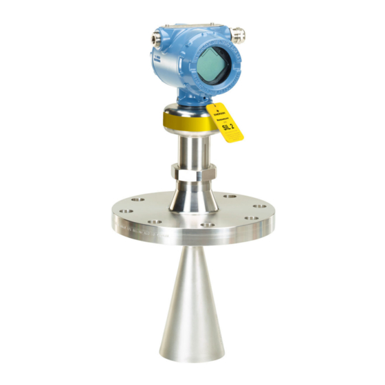
Page 17: Components Of The Transmitter
J. Threaded process connection (NPT or BSPP (G)) K. Air purge ring (option code PC1 for cone antenna) L. Integrated air purge connection M. Parabolic antenna N. Parabolic antenna with swivel mount O. Process seal antenna ® P. Tri-Clamp process connection Rosemount 5408 and 5408:SIS Level Transmitters... -
Page 18: System Integration
Application), a handheld communicator, the AMS Device Manager, or any other Device Descriptor (DD) or Field Device Integration (FDI) compatible host system. The Rosemount 5408 and 5408:SIS are compliant with NAMUR NE 107 Field Diagnostics for standardized device diagnostic information. Reference Manual... - Page 19 B. Rosemount 5408 C. Rosemount 751 D. Handheld communicator E. Approved IS barrier (for Intrinsically Safe installations only) F. Rosemount 333 G. Host/DCS system H. HART modem I. Rosemount Radar Master Plus or AMS Device Manager Rosemount 5408 and 5408:SIS Level Transmitters...
- Page 20 Transmitter overview Reference Manual February 2020 00809-0100-4408 Reference Manual...
-
Page 21: Chapter 3 Mechanical Installation
Verify that the operating atmosphere of the transmitter is consistent with the appropriate hazardous locations certifications. Confirm approval type For hazardous locations transmitters labeled with multiple approval types: Procedure Permanently mark the checkbox of the selected approval type(s). Rosemount 5408 and 5408:SIS Level Transmitters... -
Page 22: Installation Considerations
Do not install the transmitter in the center of the tank. • Do not mount close to or above the inlet stream. • Multiple Rosemount 5408 and 5408:SIS Level Transmitters can be used in the same tank without interfering with each other. Reference Manual... - Page 23 Therefore the following minimum clearance, according to Table 3-1, must be maintained. For easy access to the transmitter, mount it with sufficient service space (see Table 3-2). Figure 3-3: Free Space Requirements Rosemount 5408 and 5408:SIS Level Transmitters...
- Page 24 Mechanical installation Reference Manual February 2020 00809-0100-4408 Table 3-1: Distance to Tank Wall (L) Application Minimum Recommended Liquids 8 in. (200 mm) ½ of tank radius Solids 8 in. (200 mm) ⅔ of tank radius Table 3-2: Free Space Requirements Description Distance Service space width (A)
- Page 25 Beam width and beam angle The transmitter should be mounted with as few internal structures as possible within the signal beam. Refer to Table 3-3 for beam angle and Table 3-4 for beam width at different distances. Rosemount 5408 and 5408:SIS Level Transmitters...
- Page 26 Mechanical installation Reference Manual February 2020 00809-0100-4408 Figure 3-5: Beam Angle and Beam Width Table 3-3: Beam Angle Antenna size Beam angle (α) 1½-in. (DN 40) cone 22° 2-in. (DN50) cone/process seal 18° 3-in. (DN80) cone/process seal 14° 4-in. (DN100) cone/process seal 10°...
- Page 27 Nozzle requirements for process seal antenna The antenna can be used on nozzles up to 4 ft. (1.2 m). Disturbing objects inside the nozzle may impact the measurement, and should therefore be avoided. Rosemount 5408 and 5408:SIS Level Transmitters...
- Page 28 Mechanical installation Reference Manual February 2020 00809-0100-4408 Figure 3-7: Mounting of the Process Seal Antenna Table 3-6: Nozzle Requirements for Process Seal Antenna Antenna size Minimum nozzle diameter (D) Recommended maximum nozzle height 2-in. (DN50) 1.77 in. (45 mm) 4 ft. (1.2 m) 3-in.
- Page 29 Maximum hole diameter is 1 in. (25 mm). • Minimum distance between holes is 6 in. (150 mm). • Holes should be drilled on one side only and deburred. • Drill one hole above maximum product surface. Rosemount 5408 and 5408:SIS Level Transmitters...
- Page 30 Mechanical installation Reference Manual February 2020 00809-0100-4408 Antenna • All cone/process seal antenna sizes can be used for still pipe/chamber installations. • The gap between the cone antenna and the still pipe should be maximum 0.2 in. (5 mm) . Larger gaps may result in inaccuracies. If required, order a larger antenna and cut on location.
- Page 31 Ensure there is no edge between the ball valve and the nozzle or still pipe, the inside should be smooth. • Valves can be combined with still pipes. • The ball valve should have the same inner diameter as the still pipe. Rosemount 5408 and 5408:SIS Level Transmitters...
-
Page 32: Mounting Preparations
Mechanical installation Reference Manual February 2020 00809-0100-4408 3.3.10 Shipboard installations Transmitters with aluminum housing are not approved for open deck installations; for use only in engine room, pump room, etc. For application conditions and limitations refer to the applicable shipboard approval. Mounting preparations 3.4.1 Assemble the segmented cone antenna... - Page 33 Shorten the extended cone antenna This section only applies to the extended cone antenna (option code S1). To determine the antenna length, follow the guidelines in section Nozzle requirements. Procedure 1. Mark where to cut the antenna. Rosemount 5408 and 5408:SIS Level Transmitters...
- Page 34 Mechanical installation Reference Manual February 2020 00809-0100-4408 2. Cut the antenna at the marking. 3. Remove any burrs. 4. Measure the Antenna Extension Length (L). 5. Update the transmitter configuration to the new Antenna Extension Length (L). • Rosemount Radar Master Plus: —...
- Page 35 Use the new stop ring supplied with the kit. Postrequisites Ensure to set the Antenna Type to Legacy (Rosemount 5402), and then set the User Defined Antenna Options parameters. Related information User defined antenna options Rosemount 5408 and 5408:SIS Level Transmitters...
-
Page 36: Mount The Cone Antenna
Mechanical installation Reference Manual February 2020 00809-0100-4408 Mount the cone antenna 3.5.1 Overview Figure 3-11: Overview A. Flanged version (see page B. Flanged version with air purge ring (see page C. Threaded version, D < d (see page D. Threaded version, D > d (see page E. - Page 37 Procedure 1. Place a suitable gasket on the tank flange. 2. Lower transmitter with antenna and flange into the nozzle. 3. Tighten bolts and nuts with sufficient torque for the flange and gasket choice. Rosemount 5408 and 5408:SIS Level Transmitters...
- Page 38 Mechanical installation Reference Manual February 2020 00809-0100-4408 Postrequisites Align the transmitter head (see Align transmitter head). 3.5.4 Flanged version with air purge ring (option code PC1) Prerequisites If applicable, assemble the segmented cone antenna (see Assemble the segmented cone antenna). Procedure 1.
- Page 39 B. 0.4 in. (10 mm) Table 3-8: Incoming Air Supply Specification Maximum pressure Recommended pressure 190 psi (13 bar) 100 to 115 psi (7 to 8 bar) Postrequisites Align the transmitter head (see Align transmitter head). Rosemount 5408 and 5408:SIS Level Transmitters...
- Page 40 Mechanical installation Reference Manual February 2020 00809-0100-4408 3.5.5 Threaded version, antenna diameter smaller than thread diameter Threaded tank connection Prerequisites If applicable, assemble the segmented cone antenna (see Assemble the segmented cone antenna). Procedure 1. Apply anti-seize paste or PTFE tape on threads according to your site procedures. Gasket may be used as a sealant for adapters with 1½- or 2-in.
- Page 41 3. Tighten the bolts and nuts with sufficient torque for the flange and gasket choice. 4. Apply anti-seize paste or PTFE tape on threads according to your site procedures. Gasket may be used as a sealant for adapters with 1½- or 2-in. BSPP (G) threads. Rosemount 5408 and 5408:SIS Level Transmitters...
- Page 42 Mechanical installation Reference Manual February 2020 00809-0100-4408 5. Lower transmitter with antenna into the nozzle. A. Gasket (for 1½-in. and 2-in. BSPP (G) threads only) Postrequisites Align the transmitter head (see Align transmitter head). 3.5.6 Threaded version, antenna diameter larger than thread diameter Prerequisites If applicable, assemble the segmented cone antenna (see...
- Page 43 4. Mount the antenna. Note Visually inspect the microwave launcher for damage and dirt. Torque 5 in-lb (0.5 N-m) H2 mm Torque 250 in-lb (28 N-m) 38 mm 5. Place a suitable gasket on the tank flange. Rosemount 5408 and 5408:SIS Level Transmitters...
- Page 44 Mechanical installation Reference Manual February 2020 00809-0100-4408 6. Lower transmitter with antenna and flange into the nozzle. 7. Tighten the bolts and nuts with sufficient torque for the flange and gasket choice. 8. Screw the adapter until it is properly tightened. Postrequisites Align the transmitter head (see Align transmitter...
- Page 45 Reference Manual Mechanical installation 00809-0100-4408 February 2020 3.5.7 Bracket mounting Procedure 1. Mount the bracket to the pipe/wall. On pipe: A. Horizontal pipe B. Vertical pipe On wall: 2. Mount the holder to the bracket. Rosemount 5408 and 5408:SIS Level Transmitters...
- Page 46 Mechanical installation Reference Manual February 2020 00809-0100-4408 3. Unscrew and remove the antenna. H2 mm Note Be careful not to scratch the microwave launcher. The microwave launcher is sensitive to mechanical impacts. 4. Screw the transmitter into the holder. 5. Mount the antenna. Torque 5 in-lb (0.5 N-m) H2 mm 38 mm...
- Page 47 Open tank Align the marking on the sensor module toward the tank wall (see Figure 3-13). Still pipe Align the external ground screw toward the holes of the still pipe (see Figure 3-14). Chamber Align the external ground screw toward the process connections (see Figure 3-15). Rosemount 5408 and 5408:SIS Level Transmitters...
- Page 48 Mechanical installation Reference Manual February 2020 00809-0100-4408 3. Tighten the nut. Torque 355 in-lb (40 N-m) 60 mm Figure 3-13: Open Tank Figure 3-14: Still pipe Figure 3-15: Chamber Reference Manual...
-
Page 49: Mount The Process Seal Antenna
B. Tri-Clamp version (see page C. Bracket mounting (see page 3.6.2 Mount the flanged version Procedure 1. Lower the transmitter into the nozzle. Note Be careful not to scratch or otherwise damage the PTFE sealing. Rosemount 5408 and 5408:SIS Level Transmitters... - Page 50 Mechanical installation Reference Manual February 2020 00809-0100-4408 2. Tighten the bolts and nuts (see Table 3-9). Note • Re-tighten after 24 hours and again after the first temperature cycle. • Check at regular intervals and re-tighten if necessary. Table 3-9: Torque Value, lb-ft (N-m) (1)(2) Process connection Process connection rating...
- Page 51 Note Be careful not to scratch or otherwise damage the PTFE sealing. 2. Tighten the clamp to the recommended torque (see the manufacturer’s instruction manual). Postrequisites Align the transmitter head (see Align transmitter head). Rosemount 5408 and 5408:SIS Level Transmitters...
- Page 52 Mechanical installation Reference Manual February 2020 00809-0100-4408 3.6.4 Bracket mounting Procedure 1. Mount the bracket to the pipe/wall. On pipe: A. Horizontal pipe B. Vertical pipe On wall: 2. Mount the transmitter to the bracket. H5 mm Reference Manual...
-
Page 53: Mount The Parabolic Antenna
Mechanical installation 00809-0100-4408 February 2020 Mount the parabolic antenna 3.7.1 Overview Figure 3-17: Overview A. Flanged version (see page B. Threaded version (see page C. Welded version (see page D. Bracket mounting (see page Rosemount 5408 and 5408:SIS Level Transmitters... - Page 54 Mechanical installation Reference Manual February 2020 00809-0100-4408 3.7.2 Components of the parabolic antenna Components of the threaded version Figure 3-18: Components A. Antenna B. Purge plug kit C. Threaded sleeve D. M20 adapter E. Lock nut BSPP (G) 3½-in. F. Antenna adapter with ball joint G.
- Page 55 B. Purge plug kit C. Threaded sleeve D. M20 adapter E. Weld protection plate F. Flange ball G. O-ring H. Clamp flange I. Washer J. M8 screw K. Weld protection bar L. Ball joint Rosemount 5408 and 5408:SIS Level Transmitters...
- Page 56 Mechanical installation Reference Manual February 2020 00809-0100-4408 3.7.3 Mount the flanged version Procedure 1. Place a suitable gasket on the tank flange. 2. Lower the flange and antenna assembly into the nozzle. 3. Tighten the bolts and nuts with sufficient torque for the flange and gasket choice. Postrequisites 1.
- Page 57 A. Ø 3.98 ± 0.02 in. (Ø 101 ± 0.6 mm) or G 3½-in. B. Max. 0.59 in. (15 mm) 4. Remove the M20 adapter and visually inspect the O-rings for damage and dirt. Rosemount 5408 and 5408:SIS Level Transmitters...
- Page 58 Mechanical installation Reference Manual February 2020 00809-0100-4408 5. Carefully insert the antenna. 6. Secure the antenna. Torque 180 in-lb (20 N-m) 27 mm 7. Tighten the set screw. Torque 5 in-lb (0.5 N-m) H2 mm Reference Manual...
- Page 59 10. Tighten the bolts and nuts with sufficient torque for the flange and gasket choice. Postrequisites 1. Adjust the inclination of the antenna (see Adjust the inclination of the antenna). 2. Connect the air purging system (see Connect the air purging). Rosemount 5408 and 5408:SIS Level Transmitters...
- Page 60 Mechanical installation Reference Manual February 2020 00809-0100-4408 3.7.5 Mount the welded version Procedure 1. Mount the protection plates to flange/manhole cover. These plates protect the internal surfaces of the flange ball from dust and sparks during welding. A. Ø 3.94 ± 0.02 in. (Ø 100 ± 0.5 mm) B.
- Page 61 5. Mount the ball joint. a) Insert the ball joint and place the clamp flange with the “7 Nm” marking side b) Gradually tighten the M8 screws. Torque 65 in-lb (7 N-m) H6 mm Rosemount 5408 and 5408:SIS Level Transmitters...
- Page 62 Mechanical installation Reference Manual February 2020 00809-0100-4408 6. Remove the M20 adapter and visually inspect the O-rings for damage and dirt. 7. Carefully insert the antenna. 8. Secure the antenna. Torque 180 in-lb (20 N-m) 27 mm Reference Manual...
- Page 63 12. Tighten the bolts and nuts with sufficient torque for the flange and gasket choice. Postrequisites 1. Adjust the inclination of the antenna (see Adjust the inclination of the antenna). 2. Connect the air purging system (see Connect the air purging). Rosemount 5408 and 5408:SIS Level Transmitters...
- Page 64 Mechanical installation Reference Manual February 2020 00809-0100-4408 3.7.6 Bracket mounting Procedure 1. Mount the bracket to the pipe/wall. On pipe: On wall: 2. Mount the antenna assembly to the bracket. H6 mm 13 mm 3. Place the supplied circular level on top of the antenna assembly. Reference Manual...
- Page 65 Reference Manual Mechanical installation 00809-0100-4408 February 2020 4. Adjust the inclination of the antenna. 5. Gradually tighten the two M8 screws. H6 mm 6. Remove the circular level. Rosemount 5408 and 5408:SIS Level Transmitters...
- Page 66 Mechanical installation Reference Manual February 2020 00809-0100-4408 7. Mount the transmitter head. Torque 355 in-lb (40 N-m) 60 mm Postrequisites 1. Connect the air purging system (see Connect the air purging). 3.7.7 Adjust the inclination of the antenna Prerequisites WARNING Contents may be under pressure.
- Page 67 2. Rotate the antenna so the air purge connection is directed toward the tank wall. 3. Place the supplied circular level on top of the antenna assembly. 4. Adjust the inclination of the antenna. Rosemount 5408 and 5408:SIS Level Transmitters...
- Page 68 Mechanical installation Reference Manual February 2020 00809-0100-4408 5. Gradually tighten the M8 screws. Torque 65 in-lb (7 N-m) H6 mm 6. Remove the circular level. Reference Manual...
- Page 69 Reference Manual Mechanical installation 00809-0100-4408 February 2020 7. Mount the transmitter head. Align the marking on the sensor module with the air purge connection. Torque 355 in-lb (40 N-m) 60 mm 36 mm Rosemount 5408 and 5408:SIS Level Transmitters...
- Page 70 Mechanical installation Reference Manual February 2020 00809-0100-4408 3.7.8 Connect the air purging Procedure • If air purging is not used, plug and seal the entry with the purge plug kit. Figure 3-20: Air Purging Torque 180 in-lb (20 N-m) 17 mm A.
-
Page 71: Adjust Display Orientation (Optional)
(up to 360° from thread limit). 3. Re-tighten the set screw. Figure 3-21: Rotate the Transmitter Housing Torque 30 in-lb (3 N-m) H3/32 in. Rosemount 5408 and 5408:SIS Level Transmitters... - Page 72 Mechanical installation Reference Manual February 2020 00809-0100-4408 Reference Manual...
-
Page 73: Chapter 4 Electrical Installation
High voltage that may be present on leads can cause electrical shock. • Ensure the mains power to the transmitter is off and the lines to any other external power source are disconnected or not powered while wiring the transmitter. Rosemount 5408 and 5408:SIS Level Transmitters... -
Page 74: Hazardous Areas
Electrical installation Reference Manual February 2020 00809-0100-4408 Hazardous areas When the transmitter is installed in hazardous areas, local regulations, and specifications in applicable certificates must be observed. Related information Product certifications Prepare the electrical connections 4.3.1 Cable selection Use 24-14 AWG wire. Twisted pairs and shielded wiring are recommended for environments with high EMI (electromagnetic interference). - Page 75 D. Connect drain wire to the power supply ground Note Do not ground the shield and its drain wire at the transmitter. If the cable shield touches the transmitter housing, it can create ground loops and interfere with communications. Rosemount 5408 and 5408:SIS Level Transmitters...
- Page 76 Electrical installation Reference Manual February 2020 00809-0100-4408 4.3.5 Power supply The transmitter operates on 12-42.4 Vdc (12-30 Vdc in Intrinsically Safe installations) at the transmitter terminals. 4.3.6 Load limitations ® For HART communication, a minimum loop resistance of 250 Ω is required. Maximum loop resistance is determined by the voltage level of the external power supply.
- Page 77 Wiring diagram ® Figure 4-4: 4-20 mA/HART Communication A. Handheld communicator B. Approved IS barrier (for Intrinsically Safe installations only) C. HART modem D. Load resistance (≥250 Ω) E. Current meter F. Power supply Rosemount 5408 and 5408:SIS Level Transmitters...
-
Page 78: Connect Wiring And Power Up
Electrical installation Reference Manual February 2020 00809-0100-4408 Figure 4-5: 4-20 mA/HART Communication - Terminal Block with TEST Terminal A. Handheld communicator B. Approved IS barrier (for Intrinsically Safe installations only) C. HART modem D. Load resistance (≥250 Ω) E. Current meter F. - Page 79 5. Connect the cable wires (see Wiring diagram). Torque 7 in-lb (0.8 N-m) 6. Ensure proper grounding (see Grounding). Unless marked, the conduit/cable entries in the transmitter housing use a ½–14 NPT thread form. Rosemount 5408 and 5408:SIS Level Transmitters...
- Page 80 Electrical installation Reference Manual February 2020 00809-0100-4408 7. Tighten the cable gland. Apply PTFE tape or other sealant to the threads. Note Make sure to arrange the wiring with a drip loop. 8. Seal any unused ports with the enclosed metal plug. Apply PTFE tape or other sealant to the threads.
-
Page 81: Optional Devices
Rosemount 333 HART Tri-Loop The Rosemount 5408 and 5408:SIS Level Transmitters output a HART signal with four process variables. By using the Rosemount 333 HART Tri-Loop, up to three additional analog 4-20 mA outputs are provided. Each Tri-Loop channel receives power from control room. Channel 1 must be powered for the Tri-Loop to operate. - Page 82 Reference Manual February 2020 00809-0100-4408 Note The operational mode on the Rosemount 5408:SIS must be set to Control/Monitoring when used with the Rosemount 333 HART Tri-Loop. Figure 4-6: Example Installation of Rosemount 333 with Rosemount 5408 A. Approved IS barrier B.
-
Page 83: Chapter 5 Configuration
High voltage that may be present on leads can cause electrical shock. Overview This chapter provides information about configuration and configuration tools. Appendix Configuration parameters provides extended information about the configuration parameters. The menu trees can be found in Menu tree. Rosemount 5408 and 5408:SIS Level Transmitters... -
Page 84: System Readiness
DD at Emerson.com/DeviceInstallKits. • If using a third party host, download the latest DD at FieldCommGroup.org/Registered-Products. • Download the latest FDI Package at Emerson.com/RosemountRadarMasterPlus. Table 5-1: Identification and Compatibility According to NAMUR NE 53 Release Device identification DD and FDI Review... -
Page 85: Get Started With Your Preferred Configuration Tool
Download the latest FDI Package To manually add/update the Rosemount Radar Master Plus FDI Package: Procedure 1. Download the latest FDI Package at Emerson.com/RosemountRadarMasterPlus. 2. Unzip/extract the FDI Package. 3. Add the FDI Package to the host system. Rosemount 5408 and 5408:SIS Level Transmitters... - Page 86 The Device Descriptor (DD) is a configuration tool that is developed to assist the user through the configuration. Prerequisites The Rosemount 5408 DD is typically installed together with AMS Device Manager. To download the latest DD, visit the Emerson Device Install Kit site at: Emerson.com/DeviceInstallKits...
-
Page 87: Confirm Hart ® Revision Capability
Configure using Rosemount Radar Master Plus The options available in the Guided Setup wizard include all items required for basic operation. Procedure 1. Start Instrument Inspector Application. 2. Under HART, double-click the device icon. Rosemount 5408 and 5408:SIS Level Transmitters... -
Page 88: Verify Level
Configuration Reference Manual February 2020 00809-0100-4408 3. From the Overview screen, select Rosemount Radar Master Plus. 4. Under Configure, select Guided Setup and follow the on-screen instructions. 5.6.2 Configure using AMS Device Manager The options available in the Guided Setup wizard include all items required for basic operation. - Page 89 Verify and adjust level measurement by comparing it to a hand-gauged measurement. Prerequisites Note Before running Verify Level, make sure that: the product surface is calm, the tank is not being filled or emptied, and the actual level is well above the tank bottom. Rosemount 5408 and 5408:SIS Level Transmitters...
-
Page 90: Establish Multidrop Communication
Configuration Reference Manual February 2020 00809-0100-4408 Procedure 1. Select Configure → Guided Setup. 2. Select Verify Level to check your level measurement, and follow the on-screen instructions. Establish multidrop communication 5.8.1 Establish multidrop communication using Rosemount Radar Master Plus Multidropping transmitters refers to the connection of several transmitters to a single communications transmission line. -
Page 91: Use With The Rosemount 333 Hart ® Tri-Loop
Variable (SV), Third Variable (TV), and Fourth Variable (QV). a) Select Configure → Manual Setup → Device Setup → HART. b) Under Variable Mapping, select variables for PV, SV, TV, and QV. 4. Set the Rosemount 5408 to Burst Mode. • HART Revision 6: a. -
Page 92: Write Protect A Transmitter
Prerequisites If the Rosemount 5408:SIS is configured for use in Safety (SIS) operational mode, then the Safety Mode must be enabled for the transmitter to become operational. When Safety Mode is enabled, the transmitter is write protected to prevent unauthorized changes. -
Page 93: Chapter 6 Operation
Figure 6-2: Startup Screen Sequence 1. All segments on 2. Device type and 3. Software revision communication protocol 4. Serial number 5. Device HART address Variable screens The transmitter can display the following variables: Rosemount 5408 and 5408:SIS Level Transmitters... - Page 94 Operation Reference Manual February 2020 00809-0100-4408 Table 6-1: LCD Display Variables Parameter Presentation on display Description Level LEVEL The current level measurement value. Distance DIST Distance from the upper reference point to the product surface. Level Rate The current velocity at which the level is moving.
-
Page 95: Set Up The Lcd Display
Current measurement data of the primary variables are presented on the Overview screen together with a graphical representation of the tank. Procedure Select All Variables to view a complete list of all variables within the transmitter. Rosemount 5408 and 5408:SIS Level Transmitters... - Page 96 Operation Reference Manual February 2020 00809-0100-4408 Figure 6-3: Rosemount Radar Master Plus - Overview Screen 6.3.2 View measurement data in AMS Device Manager and handheld communicator Current measurement data of the primary variables are presented on the Overview screen. To view all current measurement values, do the following: Procedure 1.
-
Page 97: Device Status
High/low user defined alert 6.4.1 Check device status Follow this procedure to check device status and see whether there are any active alerts reported. Procedure 1. Go to the Overview screen to view the overall device status. Rosemount 5408 and 5408:SIS Level Transmitters... - Page 98 Operation Reference Manual February 2020 00809-0100-4408 2. If status is anything than Good, click the button in the device status image to open a window with active alerts. The different device status images are shown in Table 6-2 Table 6-3. Active Alerts can also be obtained via Service Tools →...
- Page 99 At least one Out of Specification Specification alert is active (and no Failure or Function Check alerts). Maintenance At least one Maintenance Required Required alert is active (and no Failure, Function Check, or Out of Specification alerts). Rosemount 5408 and 5408:SIS Level Transmitters...
- Page 100 Operation Reference Manual February 2020 00809-0100-4408 Reference Manual...
-
Page 101: Service And Troubleshooting
Ensure the mains power to the transmitter is off and the lines to any other external power source are disconnected or not powered while wiring the transmitter. Diagnostic messages Diagnostic messages per NAMUR NE 107 are listed in Table 7-1 Table 7-5. Rosemount 5408 and 5408:SIS Level Transmitters... - Page 102 Service and troubleshooting Reference Manual February 2020 00809-0100-4408 Table 7-1: Status - Failed LCD display Host diagnostic Description Recommended actions message message ELEC Electronics Failure, An electronics error has occurred. 1. Restart the device. Transmitter FAILUR The device measurement reading is 2.
- Page 103 1. Check that the value pairs in the Error incorrect. scaled variable table are entered in increasing order. 2. Check the number of table points to use is correct. 3. If condition persists, restore default settings, and reconfigure the device. Rosemount 5408 and 5408:SIS Level Transmitters...
- Page 104 Configuration Error supported. supported by device. Note 2. Consider purchasing an upgrade of the device to access additional Rosemount 5408:SIS only supports level or variables. distance as Primary Variable. Measurement Correction The factory measurement correction data 1. Restore default settings and Configuration Error is invalid.
- Page 105 2. If condition persists, restore default settings and reconfigure device. Burst Mode Configuration The burst mode configuration is incorrect. 1. Check configuration of burst mode. Error 2. If condition persists, restore default settings and reconfigure device. Rosemount 5408 and 5408:SIS Level Transmitters...
- Page 106 Error device is invalid. using the Upgrade function. Note 2. If condition persists, contact your local Emerson representative to get a Start codes are unique for individual valid start code. devices and cannot be copied from one device to another.
-
Page 107: Troubleshooting Guides
If there is a malfunction despite the absence of alerts, follow the procedures described in the appropriate troubleshooting guide. Under each of the symptoms, specific suggestions for solving problems are offered. Related information Incorrect level readings Troubleshooting the 4-20 mA/HART Output Rosemount 5408 and 5408:SIS Level Transmitters... - Page 108 Service and troubleshooting Reference Manual February 2020 00809-0100-4408 7.3.1 Incorrect level readings Table 7-6: Incorrect Level Readings Symptom Possible causes Recommended actions Reported level is too high or low. Incorrect tank geometry • Verify the tank geometry parameters configuration. are configured correctly (especially the Reference Height).
- Page 109 Product surface is within the Check the setting of the Upper Null Zone, product surface is close to antenna. Upper Null Zone and a Upper null zone. disturbance echo is interpreted as the product surface. Time Rosemount 5408 and 5408:SIS Level Transmitters...
- Page 110 Service and troubleshooting Reference Manual February 2020 00809-0100-4408 Table 7-6: Incorrect Level Readings (continued) Symptom Possible causes Recommended actions Measured value jumps to a lower value. Multiple products in the tank, Set Double Surface Handling to Track e.g. thin oil layer on top of Upper Surface or Track Lower Surface, see water that is sometimes Double surface...
- Page 111 • Enable the Tank Bottom Projection function, see Use tank bottom projection. • Enable the Bottom echo visible when tank is empty parameter, see Enable bottom echo visible when tank is empty. Time Rosemount 5408 and 5408:SIS Level Transmitters...
- Page 112 Service and troubleshooting Reference Manual February 2020 00809-0100-4408 Table 7-6: Incorrect Level Readings (continued) Symptom Possible causes Recommended actions When the product surface is near the Reduction of projected • Verify the tank geometry parameters sloped tank bottom, the transmitter enters surface area close to sloping are configured correctly (especially the alarm mode.
-
Page 113: Service And Troubleshooting Tools
This section briefly describes tools and functions in the Rosemount Radar Master Plus, AMS Device Manager, and handheld communicator, which may be useful for service and troubleshooting of the Rosemount 5408 and 5408:SIS Level Transmitters. 7.4.1 Using the echo curve The Rosemount Radar Master Plus software includes functions for viewing and recording single instances or movies of the echo curve. - Page 114 Service and troubleshooting Reference Manual February 2020 00809-0100-4408 Figure 7-1: Echo Curve Measurement problems can be understood by studying the position and amplitude of the different peaks. Additionally, the recorded echo curves give insight into unexpected and intermittent measurement behaviors, for instance, at the time of the triggered alert. Read the echo curve To read the echo curve in Rosemount Radar Master Plus: Procedure...
- Page 115 You can zoom in to a specific area of the echo curve. Procedure • To zoom in, drag a rectangle around the area you want to magnify. • To zoom out, in the upper right corner of the echo curve, select Reset Zoom. Rosemount 5408 and 5408:SIS Level Transmitters...
- Page 116 Service and troubleshooting Reference Manual February 2020 00809-0100-4408 View level trends and historical echo curves Procedure • To go to a desired point in the displayed part of the timeline, drag the slider, or click anywhere in the timeline. • To move the timeline forward or backward, click the left or right arrow, or drag anywhere in the timeline.
- Page 117 To set the resolution of the level trend timeline: Procedure 1. Under Service Tools, select Echo Curve. 2. Select Options. 3. In the Timeline Resolution list, select the desired length (in hours) of the timeline. 4. Select Save. 5. Select Back. Rosemount 5408 and 5408:SIS Level Transmitters...
- Page 118 Service and troubleshooting Reference Manual February 2020 00809-0100-4408 7.4.2 Managing disturbance echoes There are two general methods for managing disturbance echoes: • Set amplitude thresholds to filter out weak disturbance echoes and noise. • Use the suppress false echoes function to manage strong disturbance echoes. Amplitude thresholds The amplitude thresholds are used to filter out noise and disturbing echoes from the product surface echo.
- Page 119 Set the endpoint of a threshold segment Procedure 1. In the echo curve, drag the endpoint up or down, or type the desired value (Figure 7-5). 2. Select Save. Figure 7-5: Endpoint A. Endpoint Rosemount 5408 and 5408:SIS Level Transmitters...
- Page 120 Service and troubleshooting Reference Manual February 2020 00809-0100-4408 Add or delete an amplitude threshold point Procedure 1. In the echo curve, select the desired amplitude threshold point, and select Split threshold or Merge with threshold below. 2. Click again on one of the amplitude threshold points and select Save. Suppressing false echoes Stationary objects with horizontal surfaces may generate strong false echoes.
- Page 121 2. In the echo curve, click at the unknown echo peak, and then select Suppress. Figure 7-7: Add False Echo Suppression Delete a false echo suppression Procedure 1. In Rosemount Radar Master Plus, under Service Tools, select Echo Curve. Rosemount 5408 and 5408:SIS Level Transmitters...
- Page 122 Service and troubleshooting Reference Manual February 2020 00809-0100-4408 2. In the echo curve, click at the left end of the false echo suppression, and then select Delete. Figure 7-8: Delete False Echo Suppression Suppress a false echo manually The false echo may also be suppressed manually if the position of the false echo is known. Procedure 1.
- Page 123 4. If Other is selected, enter the desired value. 5. Select Start. 6. Measure the loop current. 7. Select Stop to end loop test. Related information Calibrate analog out using Rosemount Radar Master Plus Rosemount 5408 and 5408:SIS Level Transmitters...
- Page 124 Service and troubleshooting Reference Manual February 2020 00809-0100-4408 Use the TEST terminal Perform an analog loop test using AMS Device Manager and handheld communicator During a loop test, the transmitter outputs a fixed value (4 mA, 20 mA, or user-selected value).
- Page 125 1. Turn the jam screw clockwise until it is completely threaded into the housing. H2.5 mm 2. Remove the cover. 3. Remove the blue plug from the TEST terminal. 4. Connect the ampere meter leads to the terminals labeled “+” and “TEST”. 5. Measure the loop current. Rosemount 5408 and 5408:SIS Level Transmitters...
- Page 126 Service and troubleshooting Reference Manual February 2020 00809-0100-4408 6. Attach the blue plug to the TEST terminal. 7. Attach and tighten the cover. a) Verify the cover jam screw is completely threaded into the housing. H2.5 mm b) Attach and tighten the cover. Make sure the cover is fully engaged.
- Page 127 4 mA and 20 mA currents. Calibration is done at factory and the analog output does not normally need to be recalibrated. Procedure 1. Select Service Tools → Maintenance → Routine Maintenance. 2. Select D/A trim and follow the on-screen instructions. Rosemount 5408 and 5408:SIS Level Transmitters...
- Page 128 Service and troubleshooting Reference Manual February 2020 00809-0100-4408 7.4.6 Save a backup file of the device configuration When configuration is finished, it is recommended to store the device configuration in a backup file for future reference using Rosemount Radar Master Plus. A backup of the device configuration will be saved to file as well as a configuration report (optional).
- Page 129 Use the simulation mode with AMS Device Manager and handheld communicator This function can be used to simulate measurements. Procedure 1. Select Service Tools → Simulate. 2. Under Simulate Measurement Values, select desired transmitter variable and follow the on-screen instructions. Rosemount 5408 and 5408:SIS Level Transmitters...
- Page 130 Service and troubleshooting Reference Manual February 2020 00809-0100-4408 7.4.10 View input registers View input registers using Rosemount Radar Master Plus Measured data is continuously stored in the input registers. By viewing the contents of the input registers, expert users can check that the transmitter works properly. Procedure 1.
- Page 131 2. To edit a holding register value: a) Select Configure → Manual Setup → Level Setup → Advanced → Expert Options → Holding Registers. b) Select Write Holding Register and follow the on-screen instructions. Rosemount 5408 and 5408:SIS Level Transmitters...
-
Page 132: Application Challenges
Service and troubleshooting Reference Manual February 2020 00809-0100-4408 Application challenges 7.5.1 Handling disturbances at top of tank There are two general methods for managing disturbance echoes at the top of the tank: • Set amplitude threshold section • Extend the Upper Null Zone Set amplitude threshold section If necessary, a customized amplitude threshold section can be used to block out disturbing echoes (e.g. - Page 133 Figure 7-10: Upper Null Zone meter 100% (20 mA) 1 000 2 000 3 000 4 000 5 000 6 000 7 000 A. Upper Null Zone B. Disturbance echo C. Amplitude threshold D. Product surface echo Rosemount 5408 and 5408:SIS Level Transmitters...
- Page 134 Service and troubleshooting Reference Manual February 2020 00809-0100-4408 7.5.2 Tracking of weak surface echoes close to tank bottom Use tank bottom projection The Tank Bottom Projection function can be used to enhance measurement performance in the tank bottom region. If the product surface echo is weak in the tank bottom region and the bottom echo is strong (typical for flat tank bottoms), the transmitter may lock on the bottom echo and report a false level measurement (empty tank).
- Page 135 F. Echo peak from tank bottom (at the electrical distance when product in the tank) Prerequisites Note Only enable this parameter if a bottom echo is visible when tank is empty. To verify this, use the echo curve function. Rosemount 5408 and 5408:SIS Level Transmitters...
- Page 136 Service and troubleshooting Reference Manual February 2020 00809-0100-4408 Procedure 1. In Rosemount Radar Master Plus, under Configure, select Level Setup → Advanced. 2. Under More Advanced Options, select Empty Tank Handling. 3. In the Empty Tank Handling list, select User Defined. 4.
- Page 137 A double bounce echo occurs when a radar signal bounces back and forth between the product surface and tank roof (or other object within the tank) before it is detected by the transmitter. Normally, these signals have a low amplitude and are ignored by the transmitter. Rosemount 5408 and 5408:SIS Level Transmitters...
- Page 138 Service and troubleshooting Reference Manual February 2020 00809-0100-4408 Figure 7-14: Double Bounce Echoes A. Distance to surface B. Distance to first double bounce C. Actual level D. Virtual level (first double bounce) E. Signal amplitude F. Distance Prerequisites Note The Double Bounce Handling function should only be used if the problem of double bounces cannot be solved by changing the mounting position.
-
Page 139: Replace The Transmitter Head
Procedure 1. Disconnect the power supply. 2. If applicable, remove the external ground cable from the transmitter head. 3. Turn the jam screw clockwise until it is completely threaded into the housing. H2.5 mm Rosemount 5408 and 5408:SIS Level Transmitters... - Page 140 Service and troubleshooting Reference Manual February 2020 00809-0100-4408 4. Remove the cover. 5. Remove all electrical leads and disconnect conduit. 6. Loosen the nut that connects the transmitter head to the process seal. 60 mm Reference Manual...
-
Page 141: Cleaning Or Replacing The Ptfe Sealing
This section applies only to transmitters with a process seal antenna. Replace the PTFE sealing if it shows any signs of damage. If it is not damaged, clean and reuse it. Remove from service Be aware of the following: Rosemount 5408 and 5408:SIS Level Transmitters... - Page 142 Service and troubleshooting Reference Manual February 2020 00809-0100-4408 • Follow all plant safety rules and procedures. • In Explosion Proof/Flameproof and Non-Incendive/Type n installations, do not remove the transmitter covers when power is applied to the unit. • Do not remove the process connection while in operation. Removing while in operation may cause process gas leaks.
- Page 143 1. Clean the cavity with a lint-free cloth. 2. Verify the O-ring on the PTFE sealing is in place. 3. Gently insert the PTFE sealing until it stops, and then firmly push it all the way in. Rosemount 5408 and 5408:SIS Level Transmitters...
- Page 144 Service and troubleshooting Reference Manual February 2020 00809-0100-4408 ® 7.7.2 Tri-Clamp version Disassembly procedures Procedure 1. Insert a wide flathead screwdriver into the groove at the base of the PTFE sealing. 2. Gently wiggle the screwdriver back and forth. Note Be careful not to scratch or depress the PTFE surfaces (facing the process).
- Page 145 1. Clean the cavity with a lint-free cloth. 2. Verify the O-ring on the PTFE sealing is in place. 3. Gently insert the PTFE sealing until it stops, and then firmly push it all the way in. Rosemount 5408 and 5408:SIS Level Transmitters...
-
Page 146: Service Support
February 2020 00809-0100-4408 Service support To expedite the return process outside of the United States, contact the nearest Emerson representative. Within the United States, call the Emerson Instrument and Valve Response Center using the 1-800-654-RSMT (7768) toll-free number. This center, available 24 hours a day, will assist you with any needed information or materials. -
Page 147: Safety Instrumented Systems (Sis) Requirements
High voltage that may be present on leads can cause electrical shock. • Ensure the mains power to the transmitter is off and the lines to any other external power source are disconnected or not powered while wiring the transmitter. Rosemount 5408 and 5408:SIS Level Transmitters... -
Page 148: Terms And Definitions
Safety Instrumented Systems (SIS) requirements Reference Manual February 2020 00809-0100-4408 Terms and definitions Table 8-1: Terms and Definitions Term Definition BPCS Basic Process Control System λ Dangerous Undetected λ Dangerous Detected λ Safe Undetected λ Safe Detected Diagnostic coverage Fraction of dangerous failures detected by automatic on- line diagnostic tests. -
Page 149: Safety Instrumented System (Sis) Certification
Safety Instrumented System (SIS) certification For safety instrumented systems usage, the 4-20 mA analog output is used as the primary safety variable. It is configured to activate the alarm function if an error occurs. If a Rosemount 5408 and 5408:SIS Level Transmitters... - Page 150 SIL 3 for random integrity @ HFT=1 • SIL 3 for systematic capability Figure 8-1: SIF Configuration Examples A. Rosemount 5408:SIS Level Transmitter (sensor) B. Logic-solver C. Actuator D. Single use 1oo1 (1-out-of-1) for SIL2 (SIL 2@ HFT=0) E. Redundant use 1oo2 for SIL3 (SIL3@ HFT=1) F.
-
Page 151: Safety Certified Identification
Dry-run prevention • Overfill prevention Safety certified identification All Rosemount 5408:SIS Level Transmitters must be identified as safety certified before installing into SIS systems. Procedure 1. Verify the transmitter model code starts with “5408F”. 2. Verify the software (SW) is 1.A3 or later. -
Page 152: Installation
Alternative means should be used to ensure process safety during such activities. 8.5.1 Measuring range The maximum measuring range is 82 ft. (25 m) for the Rosemount 5408:SIS Level Transmitter in Safety (SIS) mode. Refer to Specifications and reference data performance specification data. - Page 153 8.6.3 Set operational mode The Rosemount 5408:SIS can be used as the level sensor in a BPCS or as a safety device in a safety instrumented system. If the Rosemount 5408:SIS is used as safety device in a Safety Instrumented System, then the operational mode must be set to Safety (SIS).
-
Page 154: Site Acceptance
The proof-tests outlined in Perform proof test for SIS applications can be used for this. Note that during startup, the Rosemount 5408:SIS always outputs Low alarm current even if the transmitter is configured for High alarm mode. Reference Manual... -
Page 155: Perform Proof Test For Sis Applications
Perform proof test for SIS applications 8.8.1 Overview The Rosemount 5408:SIS Level Transmitter must be tested at regular intervals to reveal faults which are undetected by automatic diagnostics. It is the user's responsibility to choose the type of testing and the frequency of these tests. - Page 156 Safety Instrumented Systems (SIS) requirements Reference Manual February 2020 00809-0100-4408 Tools required • HART host/communicator or Rosemount Radar Master Plus • Current meter • Safety logic solver • Independent measuring device (e.g. BPCS level sensor, measuring tape) 8.8.2 Perform 1-point level and analog output verification Prerequisites WARNING During the proof-test, the transmitter will not output measurement values corresponding...
- Page 157 To end loop test, select Cancel (ABORT on Field Communicator). 4. Simulate 20.00 mA output and verify loop current. a) Select Service Tools → Simulate. b) Under Analog Out, select Loop test. Rosemount 5408 and 5408:SIS Level Transmitters...
- Page 158 Safety Instrumented Systems (SIS) requirements Reference Manual February 2020 00809-0100-4408 c) Select 20mA and then select Next (Enter on Field Communicator). d) Measure loop current (e.g. reading the safety logic solver or using the TEST terminal, see Use the TEST terminal).
- Page 159 1. Prior to the test, ensure there are no alarms or warnings present in the transmitter. a) Select Service Tools → Alerts. 2. Bypass the process safety function and take appropriate action to avoid a false trip. Rosemount 5408 and 5408:SIS Level Transmitters...
- Page 160 Safety Instrumented Systems (SIS) requirements Reference Manual February 2020 00809-0100-4408 3. Simulate 4.00 mA output and verify loop current. a) Select Service Tools → Simulate. b) Under Analog Out, select Loop test. c) Select 4mA and then select Next (Enter on Field Communicator). d) Measure loop current (e.g.
-
Page 161: Specifications
Go.EmersonProcess.com/Contact-Us (Contact Us). Specifications The Rosemount 5408:SIS must be operated according to the functional and performance specifications provided in Specifications and reference data. Command 2: Analog output current and Percent of range Command 3: Device variables (PV, SV, TV, and QV) and Analog... - Page 162 Safety Instrumented Systems (SIS) requirements Reference Manual February 2020 00809-0100-4408 8.9.1 Failure rate data FMEDA report includes failure rate data, assessment details, and assumptions regarding failure rate analysis. 8.9.2 Safety deviation ±2.0% of analog output span 8.9.3 Transmitter response time •...
-
Page 163: Appendix A Specifications And Reference Data
Refers to inaccuracy according to IEC 60770-1 when excluding installation dependent offset. See the IEC 60770-1 standard for a definition of radar specific performance parameters and if applicable corresponding test procedures. (10) Ambient temperature effect specification valid over temperature range -40 °F to 176 °F (-40 °C to 80 °C). Rosemount 5408 and 5408:SIS Level Transmitters... - Page 164 50 (15) 82 (25) in Safety (SIS) mode The Rosemount 5408:SIS has two operational modes: Safety (SIS) and Control/Monitoring. Safety (SIS) mode must be set when used in Safety Instrumented Systems. Control/Monitoring mode is intended for use in a Basic Process Control System (BPCS).
- Page 165 • IACS UR E10 test 7 For compliance with these standards, the transmitter housing must be fully engaged into the sensor module. This is achieved by rotating the transmitter housing clockwise to thread limit. Rosemount 5408 and 5408:SIS Level Transmitters...
-
Page 166: Functional Specifications
• EN 61326-2-3 (11) • NAMUR recommendations NE21 For Rosemount 5408:SIS, the blue plug on the terminal block must be connected. Pressure Equipment Directive (PED) Complies with 2014/68/EU article 4.3 Built-in lightning protection EN 61326, IEC 61000-4-5, level 6kV Radio approvals •... - Page 167 Data can be read remotely by using the Rosemount 751 Field Signal Indicator, see the corresponding Product Data Sheet for more information. Configuration tools • Rosemount Radar Master Plus for Rosemount 5408 Series (accessible through any Field ™ (14) Device Integration (FDI) based tool, e.g Instrument Inspector Application •...
- Page 168 Specifications and reference data Reference Manual February 2020 00809-0100-4408 • Field Device Integration (FDI) based systems Damping (15) User selectable (default is 2 s, minimum is 0 s) Output units • Level and distance: ft., in., m, cm, mm • Level rate: ft/s, in./min, in./s, m/h, m/s •...
- Page 169 Use 24-14 AWG wire. Twisted pairs and shielded wiring are recommended for environments with high EMI (electromagnetic interference). Use wire rated at least 5 °C above maximum ambient temperature. Two wires can be safely connected to each terminal screw. Rosemount 5408 and 5408:SIS Level Transmitters...
- Page 170 Specifications and reference data Reference Manual February 2020 00809-0100-4408 Analog signal on alarm The transmitter automatically and continuously performs self-diagnostic routines. If a failure or a measurement error is detected, the analog signal will be driven offscale to alert the user. High or low failure mode is user-configurable. Table A-4: Signal on Alarm Standard High...
- Page 171 (50) (38.5) (25) 44 (3) -15 (-1) (-40) (38) (100) (150) (200) (-60) (250) A. Pressure psig (bar) B. Temperature °F (°C) C. Code CAC D. Code CAB E. Code CAA F. Code CAD Rosemount 5408 and 5408:SIS Level Transmitters...
- Page 172 Specifications and reference data Reference Manual February 2020 00809-0100-4408 Figure A-5: Cone Antenna (PEEK Seal) (52) (-30) (-15) (-1) (-60) (-25) (170) (200) (220) (250) A. Pressure psig (bar) B. Temperature °F (°C) C. Code CBF (FVMQ) ® D. Code CBV (Viton E.
- Page 173 316L SST according to ASME B16.5 Table 2-2.3 (for protective plate design) • Alloy C-276 (UNS N10276) according to ASME B16.5 Table 2-3.8 • Alloy 400 (UNS N04400) according to ASME B16.5 Table 2-3.4 (16) Flange rating according to backing flange. Rosemount 5408 and 5408:SIS Level Transmitters...
- Page 174 Specifications and reference data Reference Manual February 2020 00809-0100-4408 • 1.4404 according to EN 1092-1 material group 13E0 • 316 SST according to JIS B2220 material group No. 2.2 (16) • 316L SST according to JIS B2220 material group No. 2.3 (for protective plate design) A.2.8 Conditions used for flange strength calculations Table A-7: 316/316L SST (EN 1.4404) Flanges...
- Page 175 If there is normally a thick layer of product build-up there, air purging is most likely needed. Typical purging media to use is air. All parabolic antennas come with an integrated air purge connection (see Figure A-9). Rosemount 5408 and 5408:SIS Level Transmitters...
- Page 176 Specifications and reference data Reference Manual February 2020 00809-0100-4408 Figure A-9: Air Purging for Parabolic Antenna An air purge connection is also available for cone antennas with flanged connection by selecting option code PC1. This option consists of an antenna with purge holes and a separate air purge ring (see Figure A-10).
-
Page 177: Physical Specifications
Emerson is not in a position to evaluate or guarantee the compatibility of the process fluid or other process parameters with the product, options, configuration or materials of construction selected. - Page 178 This declaration is applicable to Tri-Clamp connections. Emerson certifies no process wetted components used in hygienic seal products contain substances of animal origin. Materials used in the production or processing of wetted components for hygienic seals meet the requirements stated in EMA/410/01 Rev. 3 and ISO 22442-1:2015.
- Page 179 316/316L SST (EN 1.4404), Alloy C-276 (UNS N10276), or Alloy 400 (UNS N04400) • PEEK polyetheretherketone ® ® • FVMQ fluorosilicone, Kalrez 6375 perfluoroelastomer, FKM fluoroelastomer, or Viton fluoroelastomer (O-ring) Process seal antenna • PTFE fluoropolymer Parabolic antenna • 316/316L SST (EN 1.4404) • PTFE fluoropolymer Rosemount 5408 and 5408:SIS Level Transmitters...
-
Page 180: Ordering Information
Ordering information A.4.1 Rosemount 5408 Level Transmitter Table A-11: Rosemount 5408 Level Transmitter Ordering Information The starred offerings (★) represent the most common options and should be selected for best delivery. The non-starred offerings are subject to additional delivery lead time. - Page 181 Reference Manual Specifications and reference data 00809-0100-4408 February 2020 Table A-11: Rosemount 5408 Level Transmitter Ordering Information (continued) ★ Canadian Intrinsically Safe; Nonincendive ★ IECEx Flameproof, Dust Ignition-proof ★ IECEx Intrinsic Safety ★ IECEx Type n ★ INMETRO Flameproof ★...
- Page 182 Specifications and reference data Reference Manual February 2020 00809-0100-4408 Table A-11: Rosemount 5408 Level Transmitter Ordering Information (continued) Process connection size (see Table A-13, Table A-14, Table A-15, and Table Available antenna types A-16) ★ 1½-in. Cone ★ 2-in./DN50/50A Cone, Process Seal ★...
- Page 183 Reference Manual Specifications and reference data 00809-0100-4408 February 2020 Table A-11: Rosemount 5408 Level Transmitter Ordering Information (continued) ★ ® Cone Antenna (PEEK seal, Viton -15 to 754 psig (-1 to 52 bar) -22 to 392 °F (-30 to 200 °C) ★...
- Page 184 Specifications and reference data Reference Manual February 2020 00809-0100-4408 Table A-11: Rosemount 5408 Level Transmitter Ordering Information (continued) Special quality assurance ★ Calibration Data Certificate Calibration Certificate and GOST Verification Certificate (only for end-destination country Russia) (16) Hydrostatic testing ★...
- Page 185 Reference Manual Specifications and reference data 00809-0100-4408 February 2020 Table A-11: Rosemount 5408 Level Transmitter Ordering Information (continued) (23) Conduit electrical connector (shipped uninstalled) ★ ® M 12, 4-pin, Male connector (eurofast ★ ® A size Mini, 4-pin, Male connector (minifast...
- Page 186 Specifications and reference data Reference Manual February 2020 00809-0100-4408 Table A-12: Rosemount 5408:SIS Level Transmitter Ordering Information (continued) ★ Liquid & Solids Level Measurement Performance class Reference accuracy ★ Ultra Accuracy ±0.04 in. (±1 mm) ★ Standard ±0.08 in. (±2 mm) Signal output ★...
- Page 187 Reference Manual Specifications and reference data 00809-0100-4408 February 2020 Table A-12: Rosemount 5408:SIS Level Transmitter Ordering Information (continued) ★ Technical Regulations Customs Union (EAC) Flameproof ★ Technical Regulations Customs Union (EAC) Intrinsic Safety ★ Technical Regulations Customs Union (EAC) Type n...
- Page 188 Specifications and reference data Reference Manual February 2020 00809-0100-4408 Table A-12: Rosemount 5408:SIS Level Transmitter Ordering Information (continued) ★ EN1092-1 PN6 ★ EN1092-1 PN16 PN10 and PN16 dimensions are identical for DN50 to DN150 ★ EN1092-1 PN40 PN25 and PN40 dimensions are identical for DN50 to DN150 ★...
- Page 189 Reference Manual Specifications and reference data 00809-0100-4408 February 2020 Table A-12: Rosemount 5408:SIS Level Transmitter Ordering Information (continued) Functional safety options ★ Extended SIS Package Diagnostic functionality (see Smart Diagnostics Suite) ★ HART Smart Diagnostics Suite HART revision configuration ★...
- Page 190 Specifications and reference data Reference Manual February 2020 00809-0100-4408 Table A-12: Rosemount 5408:SIS Level Transmitter Ordering Information (continued) ★ NACE Material Recommendation per NACE MR0175/ISO 15156 and NACE MR0103/ISO 17945 (13) Welding procedure qualification record documentation ★ Welding Procedure Qualification Record (WPQR) ★...
-
Page 191: Availability Of Process Connections
Specifications and reference data 00809-0100-4408 February 2020 The Rosemount 5408:SIS has two operational modes: Safety (SIS) and Control/Monitoring. Safety (SIS) mode must be set when used in Safety Instrumented Systems. Control/Monitoring mode is intended for use in a Basic Process Control System (BPCS). - Page 192 Specifications and reference data Reference Manual February 2020 00809-0100-4408 F = Flat Face (process connection type code F); R = Raised Face (process connection type code R); T = Ring Type Joint (process connection type code T) Forged one-piece flange (see Figure A-20).
-
Page 193: Spare Parts And Accessories
W = Welded connection (process connection type code W) R = Raised Face face (process connection type code R) F = Flat Face face (process connection type code F) Spare parts and accessories Table A-17: Rosemount 5408 Series Spare Parts List - Transmitter Head Model Product Description 5408... - Page 194 Specifications and reference data Reference Manual February 2020 00809-0100-4408 Table A-17: Rosemount 5408 Series Spare Parts List - Transmitter Head (continued) Hazardous locations certifications None ATEX Flameproof ATEX Intrinsic Safety ATEX Type n USA Explosion-proof, Dust Ignition-proof USA Intrinsically Safe; Nonincendive Canadian Explosion-proof, Dust Ignition-proof Canadian Intrinsically Safe;...
- Page 195 Reference Manual Specifications and reference data 00809-0100-4408 February 2020 Table A-17: Rosemount 5408 Series Spare Parts List - Transmitter Head (continued) Antenna size None (Spare Transmitter Head) Options (include with selected model number) Display LCD Display Functional safety options (profile code F only)
- Page 196 Safety Instrumented Systems. Control/Monitoring mode is intended for use in a Basic Process Control System (BPCS). Note that for the Rosemount 5408:SIS (profile code F), solids level measurement is only available when operating in Control/Monitoring mode.
- Page 197 Reference Manual Specifications and reference data 00809-0100-4408 February 2020 Table A-18: Rosemount 5408 Series Spare Parts List - Antenna (continued) Profile None (Spare Antenna) Measurement type None (Spare Antenna) Performance class None (Spare Antenna) Signal output None (Spare Antenna) Housing material...
- Page 198 Specifications and reference data Reference Manual February 2020 00809-0100-4408 Table A-18: Rosemount 5408 Series Spare Parts List - Antenna (continued) 3½-in. Parabolic 4-in./DN100/100A Cone, Process Seal 6-in./DN150/150A Cone 8-in./DN200/200A Cone, Parabolic 10-in./DN250/250A Parabolic None (use when ordering bracket mounting) Process connection rating (see...
- Page 199 Reference Manual Specifications and reference data 00809-0100-4408 February 2020 Table A-18: Rosemount 5408 Series Spare Parts List - Antenna (continued) Antenna size Available antenna types 1½-in. (DN40) Cone (PTFE seal) 2-in. (DN50) Cone, Process Seal 3-in. (DN80) Cone, Process Seal 4-in.
- Page 200 Specifications and reference data Reference Manual February 2020 00809-0100-4408 Table A-18: Rosemount 5408 Series Spare Parts List - Antenna (continued) Dye penetration test certificate Certificate of Liquid Penetrant Inspection Positive material identification certificate Positive Material Identification Certificate of Conformance (17)
-
Page 201: Dimensional Drawings
1.85 in. (47 mm) 5.39 in. (137 mm) 3-in. (DN80) 6.02 in. (153 mm) 2.64 in. (67 mm) 6.77 in. (172 mm) 4-in. (DN100) 6.93 in. (176 mm) 3.62 in. (92 mm) 7.80 in. (198 mm) Rosemount 5408 and 5408:SIS Level Transmitters... - Page 202 Specifications and reference data Reference Manual February 2020 00809-0100-4408 Figure A-12: Cone Antenna with Threaded Process Connection 5.16 (131) 4.21 4.51 (107) (114.5) 11.02 (280) A. See Table A-20 for dimensions. B. See Table A-20 for dimensions. C. s60 D. NPT 1½-, 2-, 3-, 4-in. E.
- Page 203 Reference Manual Specifications and reference data 00809-0100-4408 February 2020 Figure A-13: Extended Cone Antenna 23.6 (600) 47.2 (1200) A. Option code S1 B. Option code S2 Dimensions are in inches (millimeters). Rosemount 5408 and 5408:SIS Level Transmitters...
- Page 204 Specifications and reference data Reference Manual February 2020 00809-0100-4408 Figure A-14: Cone Antenna with Bracket Mounting 5.60 (142) A. Pipe mounting (vertical pipe) B. Pipe diameter, max 2.52 in. (64 mm) C. Wall mounting (see Figure A-19 for hole pattern) D.
- Page 205 B. ½-14 NPT, M20 x 1.5, or G½; optional adapters: eurofast and minifast C. s60 D. 3-in. (DN80) and 4-in. (DN100) process seal style ® E. 2-in. Tri-Clamp F. 3-in. Tri-Clamp G. 4-in. Tri-Clamp Dimensions are in inches (millimeters). Rosemount 5408 and 5408:SIS Level Transmitters...
- Page 206 Specifications and reference data Reference Manual February 2020 00809-0100-4408 Figure A-16: Process Seal Antenna with Bracket Mounting 6.42 (163) A. Pipe mounting (vertical pipe) B. Pipe diameter, max 2.52 in. (64 mm) C. Wall mounting (see Figure A-19 for hole pattern) D.
- Page 207 F. Threaded connection G. Purge plug kit (supplied) H. Welded connection I. BSPP (G) 3½-in. J. Lock nut (supplied) 1. Maximum flange thickness (with lock nut): 0.59 in. (15 mm) Dimensions are in inches (millimeters). Rosemount 5408 and 5408:SIS Level Transmitters...
- Page 208 Specifications and reference data Reference Manual February 2020 00809-0100-4408 Figure A-18: Parabolic Antenna with Bracket Mounting 5.55 (141) A. Pipe mounting (vertical pipe) B. Pipe diameter, max 2.52 in. (64 mm) C. Wall mounting (see Figure A-19 for hole pattern) Dimensions are in inches (millimeters).
- Page 209 Standard Face type including protective plate Plate surface finish, R ASME B16.5 Raised face 3.2-6.3 µm EN 1092-1 Raised face 3.2-6.3 µm JIS B2220 Raised face 3.2-6.3 µm Figure A-21: Parabolic Antenna Flange Connection Rosemount 5408 and 5408:SIS Level Transmitters...
- Page 210 Specifications and reference data Reference Manual February 2020 00809-0100-4408 Table A-23: Standard Flanges for Parabolic Antenna Standard Face type Face surface finish ASME B16.5 Raised face 125-250 µin EN 1092-1 Type A flat face 3.2-12.5 µm JIS B2220 Raised face 3.2-12.5 µm Face gasket surface is serrated per mating standard.
-
Page 211: Appendix B Product Certifications
5408 and 5408:SIS Product Certifications document. The most recent revision of the EU Declaration of Conformity can be found at Emerson.com/Rosemount. Safety Instrumented Systems (SIS) SIL 3 Capable: IEC 61508 certified for use in safety instrumented systems up to SIL 3 (Minimum requirement of single use (1oo1) for SIL 2 and redundant use (1oo2) for SIL 3). -
Page 212: Fcc
Product certifications Reference Manual February 2020 00809-0100-4408 Note: This equipment has been tested and found to comply with the limits for a Class B digital device, pursuant to part 15 of the FCC Rules. These limits are designed to provide reasonable protection against harmful interference in a residential installation. -
Page 213: Radio Equipment Directive (Red) 2014/53/Eu
Division marked equipment in Zones and Zone marked equipment in Divisions. The markings must be suitable for the area classification, gas, and temperature class. This information is clearly defined in the respective codes. Rosemount 5408 and 5408:SIS Level Transmitters... -
Page 214: Usa
Product certifications Reference Manual February 2020 00809-0100-4408 B.9.1 E5 Explosionproof (XP), Dust-Ignitionproof (DIP) Certificate FM-US FM16US0010X Standards FM Class 3600 – 2018; FM Class 3615 – 2018; FM Class 3810 – 2005; ANSI/ISA 60079-0 – 2013; ANSI/UL 60079-1 – 2015; ANSI/UL 60079-26 ®... - Page 215 I5 Intrinsic Safety (IS), Non-Incendive (NI) Certificate FM-US FM16US0010X Standards FM Class 3600 – 2018; FM Class 3610 – 2018; FM Class 3611 – 2018; FM Class 3810 – 2005; ANSI/ISA 60079-0 – 2013; ANSI/UL 60079-11 – Rosemount 5408 and 5408:SIS Level Transmitters...
- Page 216 Product certifications Reference Manual February 2020 00809-0100-4408 ® 2014; ANSI/UL 60079-26 – 2017; ANSI/NEMA 250 – 1991; ANSI/IEC 60529 – 2014; ANSI/ISA 12.27.01:2011 Markings IS CL I, ll, lll DIV 1, GRPS A-G T4…T2 NI CL I, DIV 2, GRPS A-D T4…T2 S CL Il, lll DIV 2, GRPS E-G T4…T3 CL l Zone 0 AEx ia IIC T4...T2 Ga CL l Zone 0/1 AEx ib IIC T4...T2 Ga/Gb...
-
Page 217: Canada
Standards C22.2 NO. 0.4-17:2017, C22.2 NO. 0.5-16:2016, C22.2 No. 25-17:2017, C22.2 No.30-M1986:1986 (R:2016), C22.2 No.94-M91:1991 (R:2011), C22.2 No. 61010-1:2004, CAN/CSA C22.2 No. 60079-0:2015 Ed. 3, C22.2 No. 60079-1:2016 Ed. 3, C22.2 No. 60079-26:2016; CAN/CSA- Rosemount 5408 and 5408:SIS Level Transmitters... - Page 218 Product certifications Reference Manual February 2020 00809-0100-4408 C22.2 No. 60079-31:2015, C22.2. 60529:2016, ANSI/ISA 12.27.01:2011 Markings XP CL I, DIV 1, GRPS A-D T6…T2 DIP CLII/III, DIV 1, GRPS E-G; T6...T3 Ex db IIC T6…T3 Gb Ex tb IIIC T85°C…T250°C Db (21) (-40 °C ≤...
- Page 219 -60 °C ≤ Ta ≤ 70 °C -60 °C to 80 °C B.10.2 I6 Intrinsically Safe and Non-Incendive Systems Certificate FM-C FM16CA0011X Standards C22.2 NO. 0.4-17:2017, C22.2 NO. 0.5-16:2016, C22.2 No. 25-17:2017, C22.2 No.94-M91:1991 (R:2011), C22.2 No. 213-16:2016, C22.2 No. Rosemount 5408 and 5408:SIS Level Transmitters...
- Page 220 Product certifications Reference Manual February 2020 00809-0100-4408 61010-1:2004, CAN/CSA C22.2 No. 60079-0:2015 Ed. 3, CAN/CSAC22.2 No. 60079-11:2014 Ed. 2, CAN/CSAC22.2 No. 60079-15:2016 Ed.2, C22.2 No. 60079-26:2016, C22.2. 60529:2016, ANSI/ISA 12.27.01:2011 Markings IS CL I, ll, lll DIV 1, GRPS A-G T4…T2 NI CL I, DIV 2, GRPS A-D T4…T2 S CL Il, lll DIV 2, GRPS E-G T4…T3 Ex ia IIC T4...T2 Ga...
-
Page 221: Europe
E1 ATEX Flameproof Certificate FM15ATEX0055X Standards EN IEC 60079-0:2018, EN 60079-1:2014, EN 60079-26:2015, EN 60079-31:2014, EN 60529+A1+A2:2013 Markings II 1/2G Ex db IIC T6…T2 Ga/Gb II 2D Ex tb IIIC T85°C… T250°C Db, IP6X Rosemount 5408 and 5408:SIS Level Transmitters... - Page 222 Product certifications Reference Manual February 2020 00809-0100-4408 -60 °C ≤ Ta ≤ +70 °C Specific Conditions of Use (X): 1. Flamepath joints are not for repair. Contact the manufacturer. 2. Plastic wire-on tag, Plastic part of Process Seal Antenna and Non-standard paint options (paint options other than Rosemount Blue) may cause risk from Electrostatic discharge.
- Page 223 Once the type of protection has been marked it shall not be changed. 6. The applicable temperature class, ambient temperature range and process temperature range of the equipment is as follows: Rosemount 5408 and 5408:SIS Level Transmitters...
- Page 224 Product certifications Reference Manual February 2020 00809-0100-4408 Temperature class / Ambient temperature range Process temperature range Maximum surface temperature Gas groups: -60 °C ≤ Ta ≤ 70 °C -60 °C to 250 °C -60 °C ≤ Ta ≤ 70 °C -60 °C to 195 °C -60 °C ≤...
-
Page 225: International
8. Display glass shall be positioned in such a way as to minimize the risk of mechanical impact. 9. The applicable temperature class, ambient temperature range and process temperature range of the equipment is as follows: Rosemount 5408 and 5408:SIS Level Transmitters... - Page 226 Product certifications Reference Manual February 2020 00809-0100-4408 Temperature class / Ambient temperature range Process temperature range Maximum surface temperature Gas & Dust groups: T2 / T250°C -60 °C ≤ Ta ≤ 70 °C -60 °C to 250 °C T3 / T200°C -60 °C ≤...
- Page 227 Module to be fully tightened and PTFE tape or pipe dope is required for cable entries and blanking plugs. See Instruction Manual on application requirements. 4. The applicable temperature class, ambient temperature range and process temperature range of the equipment is as follows: Rosemount 5408 and 5408:SIS Level Transmitters...
-
Page 228: Brazil
Product certifications Reference Manual February 2020 00809-0100-4408 Temperature class / Ambient temperature range Process temperature range Maximum surface temperature -34 °C ≤ Ta ≤ 70 °C -34 °C to 250 °C -34 °C ≤ Ta ≤ 70 °C -34 °C to 195 °C -34 °C ≤... -
Page 229: China
Ex iaD 20 T85 250 Da ∼ Tamb = -60 °C to +70 °C ® Safety parameter HART Voltage U 30 V Current I 133 mA Power P 1.0 W Capacitance C 7.3 nF Inductance L Rosemount 5408 and 5408:SIS Level Transmitters... -
Page 230: Technical Regulations Customs Union (Eac)
Product certifications Reference Manual February 2020 00809-0100-4408 Specific Conditions of Use (X): 1. See certificate. B.14.3 N3 Type N: Non-Sparking Certificate NEPSI GYJ17.1226X GB3836.1-2010, GB3836.8-2014 Standards Markings Ex nA IIC T4 T2 Gc ∼ Tamb = -34 °C to +70 °C; IP65 V ≤... - Page 231 IM Technical Regulations Customs Union (EAC) Intrinsic Safety Certificate TC RU C-SE.AA87.B00756 Markings 0Ex ia IIC T4…T2 Ga X Ga/Gb Ex ib IIC T4…T2 X Ex ia IIIC T85°C …T250°C Da X Tamb = -60 °C to +70 °C Rosemount 5408 and 5408:SIS Level Transmitters...
- Page 232 Product certifications Reference Manual February 2020 00809-0100-4408 ® Safety parameter HART Voltage U 30 V Current I 133 mA Power P 1.0 W Capacitance C 7.3 nF Inductance L Specific Conditions of Use (X): 1. The Model 5408 Level Transmitter will not pass the 500Vrms dielectric strength test according to clause 6.3.13 GOST 31610.11-2014 (IEC 60079-11:2011) between the circuits and the earth ground.
-
Page 233: Japan
E4 Flameproof Certificate CML 17JPN1206X Markings Ex d IIC T6…T2 Ga/Gb Tamb = -40 °C to +70 °C Specific Conditions of Use (X): 1. See certificate. B.17 India B.17.1 Intrinsic Safety Certificate PESO P403812 Rosemount 5408 and 5408:SIS Level Transmitters... -
Page 234: Republic Of Korea
Product certifications Reference Manual February 2020 00809-0100-4408 Markings Ex ia IIC T4…T2 Ga B.17.2 Flameproof Safety Certificate PESO P403810 Markings Ex db IIC T6…T2 Ga/Gb B.17.3 Intrinsic Safety and Flameproof Certificate PESO P402545, PESO P452909/2, PESO P452909/3 Markings Ex ia IIC T4…T2 Ga Ex ib IIC T4…T2 Ga/Gb Ex db IIC T6…T2 Ga/Gb B.17.4... -
Page 235: Additional Certifications
Class Notations: AUT-UMS, AUT-CCS, AUT-PORT and AUT-IMS. B.19.3 SDN Det Norske Veritas Germanischer Lloyd (DNV GL) Type Approval Certificate TAA0000230 Intended Use DNV GL rules for classification – Ships, offshore units, and high speed and light craft. Rosemount 5408 and 5408:SIS Level Transmitters... - Page 236 Product certifications Reference Manual February 2020 00809-0100-4408 Table B-9: Application Location classes Temperature Humidity Vibration Enclosure Enclosure Class B for aluminum housing B.19.4 SLL Lloyd’s Register (LR) Type Approval Certificate 19/20012 Application Marine applications for use in environmental categories ENV1, ENV 2, (22) ENV 3 and ENV 5 as defined in Lloyd’s Register’s Type Approval...
- Page 237 5. That any unused cable entries are sealed with suitable plugs to maintain the ingress protection ratings. B.19.9 Pattern approval Belarus Pattern Approval Certificate No. 12954 Kazakhstan Pattern Approval Certificate KazInMetr No. 15466 Russia Pattern Approval Certificate VNIIMS No. SE.C.29.004.A No 70968 Rosemount 5408 and 5408:SIS Level Transmitters...
-
Page 238: Installation Drawings
Product certifications Reference Manual February 2020 00809-0100-4408 Uzbekistan Pattern Approval Certificate No. 02.7102 B.20 Installation drawings The installation guidelines presented by the System Control Drawing must be followed in order to maintain certified ratings for installed transmitters. Reference Manual... - Page 239 Reference Manual Product certifications 00809-0100-4408 February 2020 Figure B-1: D7000002-885 - System Control Drawing Rosemount 5408 and 5408:SIS Level Transmitters...
- Page 240 Product certifications Reference Manual February 2020 00809-0100-4408 Reference Manual...
- Page 241 Reference Manual Product certifications 00809-0100-4408 February 2020 Rosemount 5408 and 5408:SIS Level Transmitters...
- Page 242 Product certifications Reference Manual February 2020 00809-0100-4408 Reference Manual...
- Page 243 Reference Manual Product certifications 00809-0100-4408 February 2020 Rosemount 5408 and 5408:SIS Level Transmitters...
- Page 244 Product certifications Reference Manual February 2020 00809-0100-4408 Reference Manual...
- Page 245 Reference Manual Product certifications 00809-0100-4408 February 2020 Rosemount 5408 and 5408:SIS Level Transmitters...
- Page 246 Product certifications Reference Manual February 2020 00809-0100-4408 Reference Manual...
- Page 247 Reference Manual Product certifications 00809-0100-4408 February 2020 Rosemount 5408 and 5408:SIS Level Transmitters...
- Page 248 Product certifications Reference Manual February 2020 00809-0100-4408 Reference Manual...
-
Page 249: Appendix C Configuration Parameters
The menu tree structure in Figure C-1 is applicable for Rosemount Radar Master Plus. For AMS Device Manager and the handheld communicator, see Figure C-2. Figure C-1: Menu Tree for Rosemount Radar Master Plus Rosemount 5408 and 5408:SIS Level Transmitters... - Page 250 Configuration parameters Reference Manual February 2020 00809-0100-4408 Figure C-2: Menu Tree for AMS Device Manager and Handheld Communicator Reference Manual...
-
Page 251: Device Setup
(but the presented level value may be less steady). Percent of range auxiliary Set this parameter to output the percent of range for another transmitter variable (in addition to the primary variable). Rosemount 5408 and 5408:SIS Level Transmitters... - Page 252 Configuration parameters Reference Manual February 2020 00809-0100-4408 Table C-1: Percent of range auxiliary Parameter Description Percent of range auxiliary The variable selected for percent of range auxiliary. 100% auxiliary Value corresponding to 100 percent range of variable selected for percent of range auxiliary. 0% auxiliary Value corresponding to 0 percent range of variable selected for percent of range auxiliary.
- Page 253 Select variables to show on the optional LCD display (option code M5). If more than one variable is selected, then the LCD display toggles between the output variables. Related information LCD display screen messages Set up the LCD display Rosemount 5408 and 5408:SIS Level Transmitters...
- Page 254 The transmitter can be write protected (with or without a password) to prevent unauthorized changes. Operational mode There are two Operational Modes to choose from for the Rosemount 5408:SIS: Control/ Monitoring and Safety (SIS). If the transmitter is used as safety device in a Safety Instrumented System, the Operational Mode must be set to Safety (SIS).
-
Page 255: Level Setup
The transmitter configuration includes setting the tank geometry parameters, see Figure Figure C-5. Figure C-4: Tank Geometry, Basic Dimensions A. Device Reference Point B. Reference Height C. Zero Level D. Vertical cylinder E. Cubical Tank F. Horizontal cylinder G. Spherical tank Rosemount 5408 and 5408:SIS Level Transmitters... - Page 256 Configuration parameters Reference Manual February 2020 00809-0100-4408 Figure C-5: Tank Geometry, All Dimensions Tank Reference Point Bottom Shape Height*/Bottom Height** Reference Height Height of Tank*/Height (of tank)** Zero Level End Shape Length*/End Length** Bottom Offset Length of Tank*/Length** Device Reference Point Vertical cylinder Reference Offset Cubical cylinder...
- Page 257 Select a tank shape that corresponds to the actual tank. If the actual tank does not match one of the pre-defined tank shapes, then select Other (e.g. level measurements of sumps, basins, or ponds). Tank top shape Form of the upper tank closure. Rosemount 5408 and 5408:SIS Level Transmitters...
- Page 258 Configuration parameters Reference Manual February 2020 00809-0100-4408 Figure C-7: Tank Top Shape A. Dome B. Flat C. Conical Tank bottom shape Form of the lower tank closure. Figure C-8: Tank Bottom Shape A. Dome B. Flat C. Conical/pyramid D. Flat, inclined (for vertical cylinder) E.
- Page 259 Figure C-10: Device Reference Point for Cone Antennas A. Device Reference Point Figure C-11: Device Reference Point for Process Seal Antennas A. Device Reference Point Figure C-12: Device Reference Point for Parabolic Antennas A. Device Reference Point Rosemount 5408 and 5408:SIS Level Transmitters...
- Page 260 Configuration parameters Reference Manual February 2020 00809-0100-4408 Reference offset Distance between the Device Reference Point and the Tank Reference Point (typically the upper side of a customer plug where levels can be manually measured). The Reference Offset parameter can be used to specify your own reference point, for example when the measured level by the transmitter should correspond with the level value obtained by hand-dipping.
- Page 261 Length of tank The longest horizontal side of a cubical tank. Top shape height The height of the shape on tank top (typically from shape floor to cap top, measured at cylinder center line). Rosemount 5408 and 5408:SIS Level Transmitters...
- Page 262 The solids measurement mode should never be used for measuring liquid products due to the solids specific signal processing method, and vice versa. Note Solid is not supported for a Rosemount 5408:SIS operating in Safety (SIS) mode. Process conditions Foam This parameter should be used if there is, or may be, surface foam.
- Page 263 . In this case, the volume to mass conversion is given by the following table: Table C-2: Example of Scaled Variable Table Number Input value (volume) Output value (mass) 0 ton 100 m 90 ton Rosemount 5408 and 5408:SIS Level Transmitters...
- Page 264 These antenna parameters are applicable to customized antennas only. The settings are typically provided by factory. When a Rosemount 5408 transmitter head is mounted on a Rosemount 5402 antenna, then select the Legacy (Rosemount 5402) antenna type and specify the antenna...
- Page 265 4-in. process seal 1.316 0.401 0.035 4.59 1.40 0.492 0.150 Default setting. The Upper Null Zone may need to be increased if there are disturbance echoes in the region close to the antenna. Rosemount 5408 and 5408:SIS Level Transmitters...
- Page 266 Configuration parameters Reference Manual February 2020 00809-0100-4408 Upper null zone The Upper Null Zone defines how close to the transmitter's reference point a level value is accepted. You can extend this value to block out disturbing echoes close to the antenna, for example from the tank nozzle or bypass well inlet.
- Page 267 Empty tank handling The Empty Tank Handling functions handle situations when the surface echo is close to the tank bottom. Rosemount 5408 and 5408:SIS Level Transmitters...
- Page 268 Configuration parameters Reference Manual February 2020 00809-0100-4408 Table C-6: Empty Tank Handling Parameter Description Empty tank detection area The Empty Tank Detection Area defines a range where it is accepted to lose the echo from the product. If the echo is lost in this range, the tank is considered empty and the level is presented as 0.
- Page 269 Upper product dielectric constant Enter the dielectric constant for the upper product. A more precise value results in better accuracy for the lower surface level. Rosemount 5408 and 5408:SIS Level Transmitters...
- Page 270 The range is configurable. See Figure C-17 for default factory settings. Figure C-17: Overfill Prevention Range 20 in. (500 mm) 100% (20 mA) 0% (4 mA) A. Device Reference Point B. Overfill Prevention Range C. Rosemount 5408:SIS D. Rosemount 5408 Reference Manual...
-
Page 271: Alert Setup
Signal Quality is a measure of the product surface echo amplitude compared to the surface threshold and noise. The Signal Quality spans from 0 to 10. A low value means that there is a risk for the noise peak to be mistaken for the product surface peak. Rosemount 5408 and 5408:SIS Level Transmitters... - Page 272 Configuration parameters Reference Manual February 2020 00809-0100-4408 Note The Signal Quality may not be 10 even if the antenna is clean. The value depends on antenna type, application conditions, configured surface threshold, as well as the condition of the antenna. Build up on the antenna and different surface conditions are factors that can result in a low (23) Signal Quality value.
- Page 273 C. Low Alert ON D. Deadband E. Limit F. The alert is active when the level value falls below the alert limit. G. The alert turns off when the value rises above the deadband. Rosemount 5408 and 5408:SIS Level Transmitters...
- Page 274 Emerson Terms and Conditions of Sale are available upon request. The Emerson logo is a Facebook.com/Rosemount trademark and service mark of Emerson Electric Co. Rosemount is a mark of one of the Youtube.com/user/RosemountMeasurement Emerson family of companies. All other marks are the property of their respective owners.