Emerson Rosemount 5408 Reference Manual
Level transmitters non-contacting radar
Hide thumbs
Also See for Rosemount 5408:
- Reference manual (274 pages) ,
- Quick start manual (37 pages) ,
- Quick start manual (20 pages)

Thank you! Your question has been received!
Related Manuals for Emerson Rosemount 5408


Summary of Contents for Emerson Rosemount 5408
- Page 1 Reference Manual 00809-0100-4408, Rev BB April 2018 ™ Rosemount 5408 and 5408:SIS Level Transmitters Non-Contacting Radar...
- Page 2 Equipment ratings and certifications are no longer valid on any products that have been damaged or modified without the prior written permission of Emerson. Any continued use of product that has been damaged or modified without the written authorization is at the customer’s sole risk...
- Page 3 The products described in this document are NOT designed for nuclear-qualified applications. Using non-nuclear qualified products in applications that require nuclear-qualified hardware or products may cause inaccurate readings. For information on Rosemount nuclear-qualified products, contact your local Emerson Sales Representative.
-
Page 5: Table Of Contents
Bracket mounting ......................36 3.5.7 Align transmitter head ....................38 Mount the process seal antenna ....................40 3.6.1 Flanged version ......................40 3.6.2 Tri-Clamp version ......................42 Mount the parabolic antenna ....................... 43 3.7.1 Flanged version ......................43 Rosemount 5408 and 5408:SIS Level Transmitters... - Page 6 Contents 3.7.2 Threaded version ......................45 3.7.3 Welded version ......................49 3.7.4 Adjust the inclination of the antenna ................53 3.7.5 Connect the air purging ....................56 Adjust display orientation (optional) .................... 57 Chapter 4 Electrical Installation ......................59 Safety messages ...........................59 Cable selection ..........................59 Cable gland/conduit ........................60 Power supply ..........................60...
- Page 7 Proof-testing ..........................138 8.8.1 Overview ........................138 8.8.2 Perform 1-point level and analog output verification ........... 139 8.8.3 Perfom 2-point level and analog output verification ............ 142 8.8.4 Perform analog output verification ................144 Rosemount 5408 and 5408:SIS Level Transmitters...
- Page 8 Antenna versions ......................164 A.3.7 Material exposed to tank atmosphere ................164 Ordering Information ......................... 165 A.4.1 Rosemount 5408 Level Transmitter ................165 A.4.2 Rosemount 5408:SIS Level Transmitter ............... 170 Availability of process connections .....................176 Spare parts and accessories ......................178 A.6.1 Accessories ........................185...
- Page 9 Security ........................225 C.2.6 Device Information ......................226 Level setup ..........................227 C.3.1 Geometry ........................227 C.3.2 Environment ........................235 C.3.3 Volume ........................236 C.3.4 Scaled variable ......................236 C.3.5 Antenna ........................237 C.3.6 Advanced ........................239 Alert setup ..........................245 Rosemount 5408 and 5408:SIS Level Transmitters...
- Page 10 Contents C.4.1 Measurement recovery ....................245 C.4.2 Signal quality alert ....................... 245 C.4.3 High/low user defined alert ..................246 Reference Manual...
-
Page 11: Chapter 1 Introduction
Appendix C provides extended information about the configuration parameters. Product recycling/disposal Recycling of equipment and packaging should be taken into consideration and disposed of in accordance with local and national legislation/regulations. Rosemount 5408 and 5408:SIS Level Transmitters... - Page 12 Introduction Reference Manual...
-
Page 13: Chapter 2 Transmitter Overview
This signal is further processed to obtain fast, reliable, and highly accurate level measurements. See Figure 2-2 for a schematic overview of the signal processing. Figure 2-1: FMCW-method Δf≈d=distance Frequency (GHz) Time (s) Transmitted signal Reflected signal Rosemount 5408 and 5408:SIS Level Transmitters... -
Page 14: Process Characteristics
Transmitter Overview Figure 2-2: Flowchart of the Signal Processing Microwave module A/D coverter Fast Fourier transform (FFT) Peak search Peak interpolation Echo tracker Echo identifier Distance filtering Variable calculation Aout handler LCD handler HART Process characteristics 2.2.1 Dielectric constant A key parameter for measurement performance is reflectivity. A high dielectric constant of the media provides better reflection and enables a longer measuring range. -
Page 15: Dust
Grain silo - small kernel grains Grain silo - large kernel grains Lime stone silo Possible No Cement - raw mill silo Cement - finished product silo Coal bin Saw dust High consistency - pulp stock Alumina Salt Rosemount 5408 and 5408:SIS Level Transmitters... -
Page 16: Vessel Characteristics
Application examples The Rosemount 5408 and 5408:SIS are ideal for level measurements over a broad range of liquid and solids applications. The transmitters are virtually unaffected by changing density, temperature, pressure, media dielectric, pH, and viscosity. Non-contacting radar level is ideal for harsh conditions such as corrosive and sticky media, or when internal tank obstructions are a limiting factor. - Page 17 Transmitter Overview Blenders and mixers The Rosemount 5408 can help you withstand the rigors of blenders and mixing tanks. Easy to install and commission, it is also unaffected by virtually any fluid property change. Open atmospheric applications The Rosemount 5408 measures reliably in open applications, from short range sumps or ponds to long range dams.
-
Page 18: Components Of The Transmitter
Transmitter Overview Bulk solids The Rosemount 5408 is the ideal solution for small to medium sized silos with rapid level changes. The narrow beam avoids internal obstructions while still keeping good level measurement. Safety applications The Rosemount 5408:SIS is the ideal choice for safety functions such as overfill prevention, level deviation monitoring or dry-run prevention. - Page 19 N. Parabolic antenna with swivel mount G. Two cable/conduit entries (½-14 NPT, M20 x 1.5, O. Process seal antenna or G½) ™ ™ Optional adapters: eurofast and minifast H. LCD display (optional) Tri-Clamp process connection Rosemount 5408 and 5408:SIS Level Transmitters...
-
Page 20: System Integration
Application), a Field Communicator, the AMS Device Manager, or any other Device Descriptor (DD) or Field Device Integration (FDI) compatible host system. The Rosemount 5408 and 5408:SIS are compliant with NAMUR NE 107 Field Diagnostics for standardized device diagnostic information. Reference Manual... - Page 21 System Architecture Emerson Wireless 775 THUM Adapter Rosemount 5408 Rosemount 751 Field Communicator Approved IS barrier (for Intrinsically Safe installations only) Rosemount 333 Host/DCS system HART modem Rosemount Radar Master Plus or AMS Device Manager Rosemount 5408 and 5408:SIS Level Transmitters...
- Page 22 Transmitter Overview Reference Manual...
-
Page 23: Chapter 3 Mechanical Installation
Verify that the operating atmosphere of the transmitter is consistent with the appropriate hazardous locations certifications. Confirm approval type For hazardous locations transmitters labeled with multiple approval types: Permanently mark the checkbox of the selected approval type(s). Rosemount 5408 and 5408:SIS Level Transmitters... -
Page 24: Installation Considerations
Do not install the transmitter in the center of the tank. • Do not mount close to or above the inlet stream. • Multiple Rosemount 5408 and 5408:SIS Level Transmitters can be used in the same tank without interfering with each other. Reference Manual... -
Page 25: Free Space Requirements
Therefore the following minimum clearance, according to Table 3-1, must be maintained. For easy access to the transmitter, mount it with sufficient service space (see Table 3-2). Figure 3-3: Free Space Requirements Rosemount 5408 and 5408:SIS Level Transmitters... -
Page 26: Antenna Size
Mechanical Installation Table 3-1: Distance to Tank Wall (L) Application Minimum Recommended ½ of tank radius Liquids 8 in. (200 mm) ⅔ of tank radius Solids 8 in. (200 mm) Table 3-2: Free Space Requirements Description Distance Service space width (A) 20 in. -
Page 27: Non-Metallic Tanks
Beam width and beam angle The transmitter should be mounted with as few internal structures as possible within the signal beam. Refer to Table 3-3 for beam angle and Table 3-4 for beam width at different distances. Rosemount 5408 and 5408:SIS Level Transmitters... - Page 28 Mechanical Installation Figure 3-5: Beam Angle and Beam Width Table 3-3: Beam Angle Antenna size Beam angle (α) 2-in. (DN50) cone/process seal 18° 3-in. (DN80) cone/process seal 14° 4-in. (DN100) cone/process seal 10° 8-in. (DN200) parabolic 4.5° Table 3-4: Beam Width, ft. (m) Beam width (W) 2-in.
-
Page 29: Nozzle Requirements
Nozzle requirements for process seal antenna The antenna can be used on nozzles up to 4 ft. (1.2 m). Disturbing objects inside the nozzle may impact the measurement, and should therefore be avoided. Rosemount 5408 and 5408:SIS Level Transmitters... - Page 30 Mechanical Installation Figure 3-7: Mounting of the Process Seal Antenna Table 3-6: Nozzle Requirements for Process Seal Antenna Recommended maximum nozzle height Antenna size Minimum nozzle diameter (D) 2-in. (DN50) 1.77 in. (45 mm) 4 ft. (1.2 m) 3-in. (DN80) 2.76 in.
-
Page 31: Still Pipe/Chamber Installations
Installation in still pipe/chamber is recommended for tanks where there are excessive foaming or turbulence. Still pipe/chamber may also be used to avoid disturbing objects in the tank. Still pipe Consider the following still pipe requirements: Rosemount 5408 and 5408:SIS Level Transmitters... - Page 32 Mechanical Installation Pipe • Pipes should be an all-metal material. • Pipe should have a constant inside diameter. • The inner surface must be smooth and clear of any rough edges. (Smooth pipe joints are acceptable, but may reduce accuracy.) •...
- Page 33 • The gap between the cone antenna and the stand pipe should be maximum 0.2 in. (5 mm). If required, order a larger antenna and cut on location. See Table A-19 antenna dimensions. Rosemount 5408 and 5408:SIS Level Transmitters...
-
Page 34: Ball Valve Installation
Mechanical Installation Figure 3-10: Chamber Requirements Min. 0.4 in. (10 mm) Min. 6 in. (150 mm) Max. 1° Max. 0.2 in. (5 mm) For more information and installation requirements, refer to the Guidelines for Choosing and Installing Radar in Stilling Wells and Bypass Chambers Technical Note. -
Page 35: Mounting Preparations
Insert the segment into the cone antenna until it bottoms. Mark where to cut the segment. Remove and cut the segment at the marking. Remove any burrs. Insert the segment into the cone antenna until it bottoms. Secure the segment to the antenna. Rosemount 5408 and 5408:SIS Level Transmitters... -
Page 36: Shorten The Extended Cone Antenna
Mechanical Installation Measure the Antenna Extension Length (L). Update the transmitter configuration to the new Antenna Extension Length (L). • Rosemount Radar Master Plus: Under Configure, select Level Setup > Antenna. • AMS Device Manager and Field Communicator: Select Configure > Manual Setup > Level Setup > Antenna. 3.4.2 Shorten the extended cone antenna This section only applies to the extended cone antenna (option code S1). - Page 37 Update the transmitter configuration to the new Antenna Extension Length (L). • Rosemount Radar Master Plus: Under Configure, select Level Setup > Antenna. • AMS Device Manager and Field Communicator: Select Configure > Manual Setup > Level Setup > Antenna. Rosemount 5408 and 5408:SIS Level Transmitters...
-
Page 38: Mount The Cone Antenna
Mechanical Installation Mount the cone antenna Figure 3-11: Overview Flanged version (see page Flanged version with air purge ring (see page Threaded version, D < d (see page Threaded version, D > d (see page Bracket mounting (see page 3.5.1 Protective cap For spare antennas, keep the protective cap in place until installing the transmitter head. -
Page 39: Flanged Version
If applicable, assemble the segmented cone antenna (see Section 3.4.1). Lower transmitter with antenna and flange into the nozzle. Gasket Tighten bolts and nuts with sufficient torque for the flange and gasket choice. Align the transmitter head (see Section 3.5.7). Rosemount 5408 and 5408:SIS Level Transmitters... -
Page 40: Flanged Version With Air Purge Ring (Option Code Pc1)
Mechanical Installation 3.5.3 Flanged version with air purge ring (option code PC1) If applicable, assemble the segmented cone antenna (see Section 3.4.1). Place a suitable gasket on the tank flange. Place the purge ring over the gasket. Place a suitable gasket over the purge ring. Note A minimum gasket thickness of 0.125 in. -
Page 41: Threaded Version, Antenna Diameter (D) < Thread Diameter (D)
100 to 115 psi (7 to 8 bar) Align the transmitter head (see Section 3.5.7). 3.5.4 Threaded version, antenna diameter (D) < Thread diameter (d) Flanged tank connection If applicable, assemble the segmented cone antenna (see Section 3.4.1). Rosemount 5408 and 5408:SIS Level Transmitters... - Page 42 Mechanical Installation Place a suitable gasket on the tank flange. Place the customer supplied flange over the gasket. Tighten the bolts and nuts with sufficient torque for the flange and gasket choice. Apply anti-seize paste or PTFE tape on threads according to your site procedures. Gasket may be used as a sealant for adapters with 1½- or 2-in.
- Page 43 Apply anti-seize paste or PTFE tape on threads according to your site procedures. Gasket may be used as a sealant for adapters with 1½- or 2-in. BSPP (G) threads. Mount the transmitter on the tank. Rosemount 5408 and 5408:SIS Level Transmitters...
-
Page 44: Threaded Version, Antenna Diameter (D) > Thread Diameter (D)
Mechanical Installation Gasket (for 1½-in. and 2-in. BSPP (G) threads only) Align the transmitter head (see Section 3.5.7). 3.5.5 Threaded version, antenna diameter (D) > Thread diameter (d) If applicable, assemble the segmented cone antenna (see Section 3.4.1). Unscrew and remove the antenna. H2 mm Note Be careful not to scratch the microwave launcher. - Page 45 Mount the antenna. Torque 5 in-lb (0.5 N-m) H2 mm Torque 250 in-lb (28 N-m) 38 mm Note Visually inspect the microwave launcher for damage and dirt. Lower transmitter with antenna and flange into the nozzle. Rosemount 5408 and 5408:SIS Level Transmitters...
-
Page 46: Bracket Mounting
Mechanical Installation Gasket Tighten the bolts and nuts with sufficient torque for the flange and gasket choice. Screw the adapter until it is properly tightened. Align the transmitter head (see Section 3.5.7). 3.5.6 Bracket mounting Mount the bracket to the pipe/wall. On pipe: Reference Manual... - Page 47 Vertical pipe On wall: Mount the holder to the bracket. Unscrew and remove the antenna. H2 mm Note Be careful not to scratch the microwave launcher. The microwave launcher is sensitive to mechanical impacts. Rosemount 5408 and 5408:SIS Level Transmitters...
-
Page 48: Align Transmitter Head
Mechanical Installation Microwave launcher Screw the transmitter into the holder. Mount the antenna. Torque 5 in-lb (0.5 N-m) H2 mm 38 mm Align the transmitter head (see Section 3.5.7). 3.5.7 Align transmitter head Loosen the nut slightly and turn the transmitter. Reference Manual... - Page 49 Align the external ground screw toward the holes of the still pipe (see Figure 3-14). Chamber Align the external ground screw toward the process connections (see Figure 3-15). Tighten the nut. Torque 355 in-lb (40 N-m) 60 mm Figure 3-13: Open Tank Rosemount 5408 and 5408:SIS Level Transmitters...
-
Page 50: Mount The Process Seal Antenna
Mechanical Installation Figure 3-14: Still pipe Figure 3-15: Chamber Mount the process seal antenna Figure 3-16: Overview Flanged version (see page Tri-Clamp version (see page 3.6.1 Flanged version Lower the transmitter into the nozzle. Reference Manual... - Page 51 Be careful not to scratch or otherwise damage the PTFE sealing. PTFE sealing Tighten the bolts and nuts (see Table 3-9). Note • Re-tighten after 24 hours and again after the first temperature cycle. • Check at regular intervals and re-tighten if necessary. Rosemount 5408 and 5408:SIS Level Transmitters...
-
Page 52: Tri-Clamp Version
Mechanical Installation Table 3-9: Torque Value, lb-ft (N-m) (1)(2) Process connection rating ASME B16.5 EN1092-1 JIS B2220 (1) (2) Process connection size Class 150 Class 300 PN10/PN16 PN25/PN40 2-in./DN50/50A 29 (40) 52 (70) 15 (20) 26 (35) 29 (40) 18 (25) 3-in./DN80/80A 33 (45) 48 (65) -
Page 53: Mount The Parabolic Antenna
Section 3.5.7). Mount the parabolic antenna Figure 3-17: Overview Flanged version (see page Threaded version (see page Welded version (see page 3.7.1 Flanged version Lower the flange and antenna assembly into the nozzle. Gasket Rosemount 5408 and 5408:SIS Level Transmitters... - Page 54 Mechanical Installation Tighten the bolts and nuts with sufficient torque for the flange and gasket choice. Adjust the inclination of the antenna (see Section 3.7.4). Connect the air purging system (see Section 3.7.5). Reference Manual...
-
Page 55: Threaded Version
Mechanical Installation 3.7.2 Threaded version Figure 3-18: Components Antenna Lock nut BSPP (G) 3½" Purge plug kit Antenna adapter with ball joint Threaded sleeve O-ring M20 adapter Procedure Remove the lock nut. Rosemount 5408 and 5408:SIS Level Transmitters... - Page 56 Mechanical Installation Mount the O-ring. Mount the antenna adapter on flange/manhole cover. Ensure the antenna adapter fits tightly to the flange/manhole cover. Ø 3.98 ± 0.02 in. (Ø 101 ± 0.6 mm) G 3½" Max. 1.18 in. (30 mm) > 0.59 in. (15 mm) Remove the M20 adapter and visually inspect the O-rings for damage and dirt.
- Page 57 Mechanical Installation Secure the antenna. Torque 180 in-lb (20 N-m) 27 mm Tighten the set screw. Torque 5 in-lb (0.5 N-m) H2 mm Lower the antenna assembly into the tank. Rosemount 5408 and 5408:SIS Level Transmitters...
- Page 58 Mechanical Installation Gasket Tighten the bolts and nuts with sufficient torque for the flange and gasket choice. Adjust the inclination of the antenna (see Section 3.7.4). Connect the air purging system (see Section 3.7.5). Reference Manual...
-
Page 59: Welded Version
Mechanical Installation 3.7.3 Welded version Figure 3-19: Components Antenna Weld protection bar Purge plug kit O-ring Threaded sleeve Ball joint M20 adapter Clamp flange Weld protection plate Washer Flange ball M8 screw Rosemount 5408 and 5408:SIS Level Transmitters... - Page 60 Mechanical Installation Procedure Mount the protection plates to flange/manhole cover. These plates protect the internal surfaces of the flange ball from dust and sparks during welding. Ø 3.94 ± 0.02 in. (Ø 100 ± 0.5 mm) Max. 1.18 in. (30 mm) Weld the flange ball.
- Page 61 Insert the ball joint and place the clamp flange with the “7 Nm” marking side up. b. Gradually tighten the M8 screws. Torque 65 in-lb (7 N-m) H6 mm Remove the M20 adapter and visually inspect the O-rings for damage and dirt. Rosemount 5408 and 5408:SIS Level Transmitters...
- Page 62 Mechanical Installation O-rings Carefully insert the antenna. Secure the antenna. Torque 180 in-lb (20 N-m) 27 mm Tighten the set screw. Torque 5 in-lb (0.5 N-m) H2 mm Lower the antenna assembly into the tank. Reference Manual...
-
Page 63: Adjust The Inclination Of The Antenna
Do not loosen the M8 screws while in operation. Attempting to do so may release pressurized gases, resulting in serious injury or death. Procedure Loosen the M8 screws until the antenna can rotate smoothly. Rosemount 5408 and 5408:SIS Level Transmitters... - Page 64 Mechanical Installation H6 mm Rotate the antenna so the air purge connection is directed toward the tank wall. Place the circular level on top of the antenna assembly. Adjust the inclination of the antenna. Reference Manual...
- Page 65 Mechanical Installation Gradually tighten the M8 screws. Torque 65 in-lb (7 N-m) H6 mm Remove the circular level. Mount the transmitter head. Align the marking on the sensor module with the air purge connection. Rosemount 5408 and 5408:SIS Level Transmitters...
-
Page 66: Connect The Air Purging
Mechanical Installation Torque 355 in-lb (40 N-m) 60 mm 36 mm 3.7.5 Connect the air purging If air purging is not used, plug and seal the entry with the purge plug kit. Reference Manual... -
Page 67: Adjust Display Orientation (Optional)
First, rotate the housing clockwise to the desired location. If the desired location cannot be achieved due to thread limit, rotate the housing counterclockwise to the desired location (up to 360° from thread limit). Re-tighten the set screw. Rosemount 5408 and 5408:SIS Level Transmitters... - Page 68 Mechanical Installation Figure 3-21: Rotate the Transmitter Housing Torque 30 in-lb (3 N-m) H3/32 in. Note In high vibration applications, the transmitter housing must be fully engaged into the sensor module to meet the vibration test specifications. This is achieved by rotating the transmitter housing clockwise to thread limit.
-
Page 69: Chapter 4 Electrical Installation
Make sure the mains power to the transmitter is off and the lines to any other external power source are disconnected or not powered while wiring the transmitter. Cable selection Use 24-14 AWG wire. Twisted pairs and shielded wiring are recommended for environments with high EMI (electromagnetic interference). Rosemount 5408 and 5408:SIS Level Transmitters... -
Page 70: Cable Gland/Conduit
Electrical Installation Two wires can be safely connected to each terminal screw. Cable gland/conduit For explosion-proof/flameproof installations, only use cable glands or conduit entry devices certified explosion-proof or flameproof. Power supply The transmitter operates on 12-42.4 Vdc (12-30 Vdc in Intrinsically Safe installations) at the transmitter terminals. -
Page 71: Wiring Diagram
HART modem Load resistance (≥250 Ω) Current meter Power supply For Rosemount 5408:SIS and Rosemount 5408 with option code EF1 (ready for upgrade to Rosemount 5408:SIS), connect the transmitter as shown in Figure 4-3. Rosemount 5408 and 5408:SIS Level Transmitters... -
Page 72: Grounding
Electrical Installation Figure 4-3: 4-20 mA/HART Communication - Terminal Block with TEST Terminal Field Communicator Approved IS barrier (for Intrinsically Safe installations only) HART modem Load resistance (≥250 Ω) Current meter Power supply Blue plug TEST terminal Note Blue plug must only be disconnected during loop current measurement procedure. Grounding Make sure grounding is done according to national and local electrical codes. -
Page 73: Connect Wiring And Power Up
Figure 4-5: Cable Shield Insulate shield Minimize distance Trim shield and insulate Connect shield back to the power supply ground Connect wiring and power up Verify the power supply is disconnected. Remove the cover. Rosemount 5408 and 5408:SIS Level Transmitters... - Page 74 Electrical Installation Remove the plastic plugs. Pull the cable through the cable gland/conduit. Identification of thread size and type Connect the cable wires (see Section 4.7). Torque 7 in-lb (0.8 N-m) (1) Unless marked, the conduit/cable entries in the transmitter housing use a ½–14 NPT thread form. Reference Manual...
- Page 75 Seal any unused ports with the enclosed metal plug. PTFE tape or other sealant Attach and tighten the covers. Make sure the covers are fully engaged. a. Verify the cover jam screws are completely threaded into the housing. Rosemount 5408 and 5408:SIS Level Transmitters...
-
Page 76: Optional Devices
™ 4.10.1 Rosemount 333 HART Tri-Loop The Rosemount 5408 and 5408:SIS Level Transmitters output a HART signal with four process variables. By using the Rosemount 333 HART Tri-Loop, up to three additional analog 4-20 mA outputs are provided. Reference Manual... - Page 77 Tri-Loop to operate. Rosemount 5408 or 5408:SIS receives power from control room. Note The operational mode on the Rosemount 5408:SIS must be set to Control/Monitoring when used with the Rosemount 333 HART Tri-Loop. Figure 4-6: Example Installation of Rosemount 333 with Rosemount 5408...
- Page 78 Electrical Installation Reference Manual...
-
Page 79: Chapter 5 Configuration
C.1. System readiness 5.3.1 Confirm correct device driver The transmitter meets the NAMUR recommendation NE 53. Verify the latest Device Descriptor (DD) or FDI Package is loaded on your systems to ensure proper communication. Rosemount 5408 and 5408:SIS Level Transmitters... -
Page 80: Get Started With Your Preferred Configuration Tool
5-1, use the HART Universal Revision and Device Revision numbers to find the correct DD or FDI Package. Download the latest DD at EmersonProcess.com/DeviceFiles. Download the latest FDI Package at Emerson.com/RosemountRadarMasterPlus. Table 5-1: Identification and Compatibility According to NAMUR NE 53 Review... -
Page 81: Rosemount Radar Master Plus
Emerson.com/InstrumentInspector Get the latest FDI Package The Rosemount 5408 FDI Package is typically installed together with Instrument Inspector. If the FDI Package is not installed, it can be found on the enclosed CD. The latest FDI Package can also be downloaded from: Emerson.com/RosemountRadarMasterPlus... -
Page 82: Field Communicator
Get the latest Device Descriptor (DD) If the DD is not installed in your Field Communicator, see the appropriate Field Communicator User’s Manual available at Emerson.com/FieldCommunicator for instructions on how to update the Field Communicator with the latest DD. Confirm HART revision capability If using HART based control or asset management systems, confirm the HART capability of those systems prior to transmitter installation. -
Page 83: Configure Device Using Guided Setup
Select Configure > Guided Setup. Select Basic Setup and follow the on-screen instructions. Verify level The Verify Level tool matches the product level reported by the device to a reference measurement (measured by using for example handgauging). Rosemount 5408 and 5408:SIS Level Transmitters... -
Page 84: Use Rosemount Radar Master Plus
Configuration If any difference, the Calibration Offset parameter will be adjusted. A minor adjustment using Calibration Offset is normal. There may, for example be a deviation between the actual tank height and the configured value. Figure 5-1: Calibration Offset Positive Calibration Offset value Negative Calibration Offset value Reported level Actual level... -
Page 85: Establish Multidrop Communication
AMS Device Manager or a Field Communicator. Procedure Make sure the transmitter is properly configured. If desired, change the measurement units. a. Select Configure > Manual Setup > Device Setup > Units. Rosemount 5408 and 5408:SIS Level Transmitters... - Page 86 Variable (SV), Third Variable (TV), and Fourth Variable (QV). a. Select Configure > Manual Setup > Device Setup > HART. b. Under Variable Mapping, select variables for PV, SV, TV, and QV. Set the Rosemount 5408 to Burst Mode. • HART Revision 6: a.
-
Page 87: Chapter 6 Operation
The optional LCD display shows output variables and abbreviated diagnostic messages. Figure 6-1: LCD Display (Option Code M5) 6.1.1 Startup screen sequence The following screens are shown on the LCD display when the transmitter is switched on: Rosemount 5408 and 5408:SIS Level Transmitters... -
Page 88: Variable Screens
Operation Figure 6-2: Startup Screen Sequence 1. All segments on 2. Device type and communica- 3. Software revision tion protocol 4. Serial number 5. Device HART address 6.1.2 Variable screens ™ The Rosemount 5408 and 5408:SIS Level Transmitters can display the following variables: Table 6-1: LCD Display Variables Presentation... -
Page 89: Set Up The Lcd Display
Current measurement data of the primary variables are presented on the Overview screen together with a graphical representation of the tank. Select All Variables to view a complete list of all variables within the transmitter. Rosemount 5408 and 5408:SIS Level Transmitters... -
Page 90: Reference Manual
Operation Figure 6-3: Rosemount Radar Master Plus - Overview Screen 6.3.2 Use AMS Device Manager and Field Communicator Current measurement data of the primary variables are presented on the Overview screen. To view all current measurement values, do the following: Select Service Tools Variables. -
Page 91: Device Status
If status is anything than Good, click the button in the device status image to open a window with active alerts. The different device status images are shown in Table 6-2 Table 6-3. Active Alerts can also be obtained via Service Tools > Alerts. Rosemount 5408 and 5408:SIS Level Transmitters... - Page 92 Operation Table 6-2: Presentation of Device Status Images as per NAMUR NE 107 - AMS Device Manager Device status image Category Description Action Good No active alert. Failure At least one Failure alert is ac- Click the Troubleshoot button to tive.
- Page 93 At least one Out of Specifica- cation tion alert is active (and no Failure or Function Check alerts). Maintenance At least one Maintenance Re- Required quired alert is active (and no Failure, Function Check, or Out of Specification alerts). Rosemount 5408 and 5408:SIS Level Transmitters...
- Page 94 Operation Reference Manual...
-
Page 95: Service And Troubleshooting
Make sure the mains power to the transmitter is off and the lines to any other external power source are disconnected or not powered while wiring the transmitter. Diagnostic messages Diagnostic messages per NAMUR NE 107 are listed in Table 7-1 Table 7-5. Rosemount 5408 and 5408:SIS Level Transmitters... - Page 96 Service and Troubleshooting Table 7-1: Status - Failed LCD display Host diagnostic mes- message sage Description Recommended actions ELEC FAILUR Electronics Failure, An electronics error has occurred. 1. Restart the device. Transmitter 2. If the condition persists, replace the device. The device measurement reading is invalid.
- Page 97 The configured tank geometry results in a 1. Check tank geometry configuration too large level measuring range for this de- and reduce Reference Height. vice. 2. If condition persists, restore default settings and reconfigure the device. Rosemount 5408 and 5408:SIS Level Transmitters...
- Page 98 2. Consider purchasing an upgrade of the device to access additional variables. Note Rosemount 5408:SIS only supports level or distance as Primary Variable. Measurement Correction The factory measurement correction data 1. Restore default settings and reconfig- Configuration Error is invalid.
- Page 99 2. Change Operational Mode to Control/Monitoring if device is This device is configured for use in not intended to be used as safe- Safety Instrumented Systems (SIS) ty device. which requires Safety Mode to be enabled. Rosemount 5408 and 5408:SIS Level Transmitters...
- Page 100 Service and Troubleshooting Table 7-3: Status - Function Check (continued) LCD display Host diagnostic mes- message sage Description Recommended actions SIMUL ACTIVE Simulation/Test Active The device is in simulation or test 1. If this behavior is not desired, mode and is not reporting actual in- stop simulation or test mode.
-
Page 101: Troubleshooting Guide
Amplitude thresholds. • Restore default settings and reconfig- ure the device. Time Level is stuck in measuring range. Incorrect alignment of the • Verify the transmitter head is correctly transmitter. aligned, see Section 3.5.7. Rosemount 5408 and 5408:SIS Level Transmitters... - Page 102 Service and Troubleshooting Table 7-6: Incorrect Level Readings (continued) Symptom Possible causes Recommended actions Disturbing objects in the • Use the suppress false echoes function tank. to manage strong disturbance echoes, Suppressing false echoes. • Analyze the echo curve and check am- plitude thresholds, see Amplitude thresholds.
- Page 103 Enable the Foam parameter or Turbu- lent Surface parameter, or both. See Process conditions. • If two surfaces are seen in foamy appli- cations, set Double Surface Handling to Track Lower Surface. See Double surface handling. Time Rosemount 5408 and 5408:SIS Level Transmitters...
- Page 104 Service and Troubleshooting Table 7-6: Incorrect Level Readings (continued) Symptom Possible causes Recommended actions Measured level is occasionally unstable. May be caused by an empty Analyze the echo curve and check ampli- tank with the amplitude tude thresholds, see Amplitude thresholds.
- Page 105 • Enable the Tank Bottom Projection function, see Use tank bottom projection. • Enable the Bottom echo visible when tank is empty parameter, see Enable bottom echo visible when tank is empty. Time Rosemount 5408 and 5408:SIS Level Transmitters...
- Page 106 Service and Troubleshooting Table 7-6: Incorrect Level Readings (continued) Symptom Possible causes Recommended actions When the product surface is near the slop- Reduction of projected sur- • Verify the tank geometry parameters ed tank bottom, the transmitter enters face area close to sloping are configured correctly (especially the alarm mode.
-
Page 107: Service And Troubleshooting Tools
This section briefly describes tools and functions in the Rosemount Radar Master Plus, AMS Device Manager, and Field Communicator, which may be useful for service and troubleshooting of the Rosemount 5408 and 5408:SIS Level Transmitters. 7.4.1 Using the echo curve The Rosemount Radar Master Plus software includes functions for viewing and recording single instances or movies of the echo curve. - Page 108 Service and Troubleshooting Figure 7-1: Echo Curve Measurement problems can be understood by studying the position and amplitude of the different peaks. Additionally, the recorded echo curves give insight into unexpected and intermittent measurement behaviors, for instance, at the time of the triggered alert. Read the echo curve To read the echo curve in Rosemount Radar Master Plus: Under Service Tools, select Echo Curve.
- Page 109 To speed up the upload time of historical data in a specific area, click or drag the slider to the desired start point on the timeline. Rosemount Radar Master Plus continues to load data from that point forward. Rosemount 5408 and 5408:SIS Level Transmitters...
- Page 110 Service and Troubleshooting View active/historical alerts In the timeline, click the left or right arrow to scroll to the alert, and then select the alert icon for details. Figure 7-3: Level Trend Timeline A. Play or pause B. Left arrow C.
-
Page 111: Managing Disturbance Echoes
Only echoes above the amplitude threshold might be considered the product surface. The amplitude threshold can either be set to a constant value, or split into sections as defined by up to 10 anchor points. Rosemount 5408 and 5408:SIS Level Transmitters... - Page 112 Service and Troubleshooting If necessary, a customized amplitude threshold section can for instance be used to remove the influence from the tank nozzle, or disturbances close to the tank bottom. Additionally, it might be needed in areas where there are occasionally strong echoes present, for instance due to wide mixer blades.
- Page 113 A. Amplitude threshold point Set the endpoint of a threshold segment In the echo curve, drag the endpoint up or down, or type the desired value (Figure 7-5). Select Save. Figure 7-5: Endpoint A. Endpoint Rosemount 5408 and 5408:SIS Level Transmitters...
- Page 114 Service and Troubleshooting Add or delete an amplitude threshold point In the echo curve, select the desired amplitude threshold point, and select Split threshold or Merge with threshold below. Click again on one of the amplitude threshold points and select Save. Suppressing false echoes Stationary objects with horizontal surfaces may generate strong false echoes.
- Page 115 In the echo curve, click at the unknown echo peak, and then select Suppress. Figure 7-7: Add False Echo Suppression Delete a false echo suppression In Rosemount Radar Master Plus, under Service Tools, select Echo Curve. Rosemount 5408 and 5408:SIS Level Transmitters...
- Page 116 Service and Troubleshooting In the echo curve, click at the left end of the false echo suppression, and then select Delete. Figure 7-8: Delete False Echo Suppression Suppress a false echo manually The false echo may also be suppressed manually if the position of the false echo is known. Procedure In Rosemount Radar Master Plus, under Service Tools, select Echo Curve.
-
Page 117: Perform An Analog Loop Test
Under Analog Out, select Loop test. Select 4mA, 20mA, or Other, and then select Next (Enter on Field Communicator). If Other is selected, enter the desired value, and then select Next (Enter on Field Communicator). Rosemount 5408 and 5408:SIS Level Transmitters... -
Page 118: Use The Test Terminal
Service and Troubleshooting Measure the loop current. To end loop test, select Cancel (ABORT on Field Communicator). 7.4.4 Use the TEST terminal WARNING! Verify that the installation is consistent with the appropriate hazardous locations certifications when the instrument used for loop current measurement is connected. For Explosion-proof/Flameproof and Non-Incendive/Type n installations, the cover must not be opened in an explosive atmosphere. - Page 119 Attach and tighten the covers. Make sure the covers are fully engaged. a. Verify the cover jam screws are completely threaded into the housing. H2.5 mm Cover jam screw (one per side) b. Attach and tighten the covers. Rosemount 5408 and 5408:SIS Level Transmitters...
-
Page 120: Calibrate Analog Out
Service and Troubleshooting c. Turn the jam screw counterclockwise until it contacts the cover. Required for explosion-proof/flameproof installations only. d. Turn the jam screw an additional ½ turn counterclockwise to secure the cover. 7.4.5 Calibrate analog out Use this function to calibrate the analog output by comparing the actual output current with the nominal 4 mA and 20 mA currents. -
Page 121: Download Configuration From File To Device
Use AMS Device Manager and Field Communicator Select Service Tools > Maintenance > Reset/Restore. Select Restore Default Settings and follow the on-screen instructions. 7.4.9 Use the simulation mode This function can be used to simulate measurements. Rosemount 5408 and 5408:SIS Level Transmitters... -
Page 122: View Input Registers
Service and Troubleshooting Use Rosemount Radar Master Plus Under Service Tools, select Simulate. Select Simulate next to desired transmitter variable and follow the on-screen instructions. Use AMS Device Manager and Field Communicator Select Service Tools > Simulate. Under Simulate Measurement Values, select desired transmitter variable and follow the on-screen instructions. -
Page 123: Write Protect A Transmitter
The transmitter can be write protected (with or without a password) to prevent unauthorized changes. If the Rosemount 5408:SIS is configured for use in Safety (SIS) operational mode, then the Safety Mode must be enabled for the transmitter to become operational. When Safety Mode is enabled, the transmitter is write protected to prevent unauthorized changes. -
Page 124: Application Challenges
Service and Troubleshooting Use AMS Device Manager and Field Communicator Select Configure > Manual Setup > Device Setup > Security. Under Security, select Change Write Protection and follow the on-screen instructions. Application challenges 7.5.1 Handling disturbances at top of tank There are two general methods for managing disturbance echoes at the top of the tank: •... - Page 125 This zone can be extended to block out disturbing echoes at the top of the tank. Note Make sure the Upper Range Value (100%/20 mA) value is below the Upper Null Zone. Measurements are not performed within the Upper Null Zone. Rosemount 5408 and 5408:SIS Level Transmitters...
-
Page 126: Tracking Of Weak Surface Echoes Close To Tank Bottom
Service and Troubleshooting Figure 7-10: Upper Null Zone Upper Null Zone Disturbance echo Amplitude threshold Product surface echo Procedure Identify desired Upper Null Zone using the echo curve plot. a. In Rosemount Radar Master Plus, start the echo curve reading, see Section 7.4.1. - Page 127 (i.e. for flat tank bottoms). The bottom echo will then be treated as a disturbance echo to facilitate tracking of weak surface echoes close to the tank bottom. This function may be useful for products which are relatively transparent for microwaves, such as oil. Rosemount 5408 and 5408:SIS Level Transmitters...
- Page 128 Service and Troubleshooting Note Only enable this parameter if a bottom echo is visible when tank is empty. To verify this, use the echo curve function. Figure 7-12: Bottom Echo Visible Product surface near bottom of tank Empty tank Signal amplitude Distance Surface echo Echo peak from tank bottom (at the electrical distance when product in the tank)
-
Page 129: Handling Ghost Echoes In Still Pipes
Section 7.4.1. Under Configure, select Level Setup > Advanced. Under More Advanced Options, select Echo Tracking. In the Surface Echo Tracking list, select User defined, and then select the Track First Echo check box. Rosemount 5408 and 5408:SIS Level Transmitters... -
Page 130: Handling Strong Double Bounce Echoes
Service and Troubleshooting Select Save. 7.5.4 Handling strong double bounce echoes A double bounce echo occurs when a radar signal bounces back and forth between the product surface and tank roof (or other object within the tank) before it is detected by the transmitter. - Page 131 The distance between each double bounce echo is constant. The Double Bounce Offset is used to define the distance between detected double bounces, as given by the following formula (see Figure 7-14): Double Bounce Offset = B - 2A Rosemount 5408 and 5408:SIS Level Transmitters...
-
Page 132: Replace The Transmitter Head
Service and Troubleshooting The Double Bounce Offset is negative if the reflection point (normally the tank roof) is below the Tank Reference Point. Replace the transmitter head In Explosion Proof/Flameproof and Non-Incendive/Type n installations, do not remove the transmitter covers when power is applied to the unit. Procedure Disconnect the power supply. - Page 133 Do not attempt to loosen it by rotating the transmitter head. If it is stuck, then it may need to be replaced with a new process connection and transmitter head, by following all plant safety rules and procedures. Rosemount 5408 and 5408:SIS Level Transmitters...
-
Page 134: Cleaning Or Replacing The Ptfe Sealing
Service and Troubleshooting Attach a protection plug to the process seal to protect it from dust and water. Process seal Cleaning or replacing the PTFE sealing This section applies only to transmitters with a process seal antenna. Replace the PTFE sealing if it shows any signs of damage. If it is not damaged, clean and reuse it. -
Page 135: Flanged Version
7.7.1 Flanged version Disassembly procedures Insert two flathead screwdrivers between the PFTE sealing and flange. Gently push the screwdriver handles forward until the PTFE sealing pops out. Carefully pull the PTFE sealing straight out. Rosemount 5408 and 5408:SIS Level Transmitters... -
Page 136: Tri Clamp Version
Service and Troubleshooting Reassembly procedures Clean the cavity with a lint-free cloth. Verify the O-ring on the PTFE sealing is in place. Gently insert the PTFE sealing until it stops, and then firmly push it all the way in. 7.7.2 Tri Clamp version Disassembly procedures Insert a wide flathead screwdriver into the groove at the base of the PTFE sealing. - Page 137 Service and Troubleshooting Repeat Step 1-Step 2 at different positions until the PTFE sealing is loose. Carefully lift the PTFE sealing. Reassembly procedures Clean the cavity with a lint-free cloth. Rosemount 5408 and 5408:SIS Level Transmitters...
-
Page 138: Service Support
Verify the O-ring on the PTFE sealing is in place. Gently insert the PTFE sealing until it stops, and then firmly push it all the way in. Service support To expedite the return process outside of the United States, contact the nearest Emerson representative. Reference Manual... - Page 139 Service and Troubleshooting Within the United States, call the Emerson Instrument and Valve Response Center using the 1-800-654-RSMT (7768) toll-free number. This center, available 24 hours a day, will assist you with any needed information or materials. The center will ask for product model and serial numbers, and will provide a Return Material Authorization (RMA) number.
- Page 140 Service and Troubleshooting Reference Manual...
-
Page 141: Safety Instrumented Systems (4-20 Ma Only)
Make sure the mains power to the transmitter is off and the lines to any other external power source are disconnected or not powered while wiring the transmitter. Terms and definitions Table 8-1: Terms and Definitions Term Definition BPCS Basic Process Control System λ Dangerous Undetected Rosemount 5408 and 5408:SIS Level Transmitters... - Page 142 Safety Instrumented Systems (4-20 mA only) Table 8-1: Terms and Definitions (continued) Term Definition λ Dangerous Detected λ Safe Undetected λ Safe Detected Diagnostic cov- Fraction of dangerous failures detected by automatic on-line diagnostic tests. erage Diagnostic test The time from when a dangerous failure/condition occurs until the device has set the safety related interval output in a safe state (total time required for fault detection and fault reaction).
-
Page 143: Safety Instrumented System (Sis) Certification
5408:SIS Level Transmitter is IEC 61508 certified accordingly: • Low and high demand: Type B element • SIL 2 for random integrity @ HFT=0 • SIL 3 for random integrity @ HFT=1 • SIL 3 for systematic capability Rosemount 5408 and 5408:SIS Level Transmitters... -
Page 144: Safety Certified Identification
Dry-run prevention • Overfill prevention Safety certified identification All Rosemount 5408:SIS Level Transmitters must be identified as safety certified before installing into SIS systems. Verify the transmitter model code starts with “5408F”. Verify the software (SW) is 1.A3 or later. -
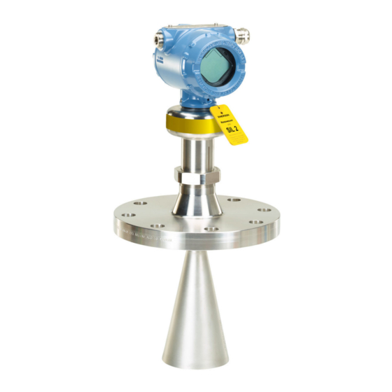
Page 145: Installation
D. Yellow stripe for locating device from distance E. Yellow tag for locating device from distance Installation The Rosemount 5408:SIS must be installed and configured as described in Chapter 3 Chapter 4. No special installation is required in addition to the standard installation practices outlined in this manual. -
Page 146: Measuring Range
8.6.3 Set operational mode The Rosemount 5408:SIS can be used as the level sensor in a BPCS or as a safety device in a safety instrumented system. If the Rosemount 5408:SIS is used as safety device in a Safety Instrumented System, then the operational mode must be set to Safety (SIS). -
Page 147: Enable Safety Mode
Figure 8-3 identifies the alarm levels available and their operation values (1) Note that during startup, the Rosemount 5408:SIS always outputs Low alarm current even if the transmitter is configured for High alarm mode. Rosemount 5408 and 5408:SIS Level Transmitters... -
Page 148: Site Acceptance
Proof-testing 8.8.1 Overview The Rosemount 5408:SIS Level Transmitter must be tested at regular intervals to reveal faults which are undetected by automatic diagnostics. It is the user's responsibility to choose the type of testing and the frequency of these tests. -
Page 149: Perform 1-Point Level And Analog Output Verification
Make sure systems and people relying on measurement values from the transmitter are made aware of the changed conditions. Failure to do so could result in death, serious injury and/or property damage. Rosemount 5408 and 5408:SIS Level Transmitters... - Page 150 Safety Instrumented Systems (4-20 mA only) Use Rosemount Radar Master Plus Prior to the test, ensure there are no alarms or warnings present in the transmitter. a. Under Service Tools, select Alerts. Bypass the process safety function and take appropriate action to avoid a false trip. Simulate 4.00 mA output and verify loop current.
- Page 151 Verify the current level or distance reading with an independent measurement is within the safety deviation of 2%. Note The inaccuracy of the independent measurement needs to be considered. Remove the bypass and otherwise restore normal operation. Rosemount 5408 and 5408:SIS Level Transmitters...
-
Page 152: Perfom 2-Point Level And Analog Output Verification
Safety Instrumented Systems (4-20 mA only) 8.8.3 Perfom 2-point level and analog output verification WARNING! During the proof-test, the transmitter will not output measurement values corresponding to the product surface level. Make sure systems and people relying on measurement values from the transmitter are made aware of the changed conditions. - Page 153 Verify the current deviation is within the safety deviation of 2% (±0.32 mA). Note The inaccuracy of safety logic solver or current meter needs to be considered. f. To end loop test, select Cancel (ABORT on Field Communicator). Rosemount 5408 and 5408:SIS Level Transmitters...
-
Page 154: Perform Analog Output Verification
Safety Instrumented Systems (4-20 mA only) Perform a two-point level measurement verification of the transmitter in the measuring range. Compare with independent measurement (e.g. the BPCS level sensor). a. Select Service Tools > Variables > Process. b. Verify the current level or distance reading with an independent measurement is within the safety deviation of 2%. -
Page 155: Product Repair
Feedback can be submitted electronically at EmersonProcess.com/Rosemount-safety (Contact Us). Specifications The Rosemount 5408:SIS must be operated according to the functional and performance specifications provided in Appendix 8.9.1 Failure rate data... - Page 156 Safety Instrumented Systems (4-20 mA only) Reference Manual...
-
Page 157: Appendix A Specifications And Reference Data
(1) Refers to inaccuracy according to IEC 60770-1 when excluding installation dependent offset. See the IEC 60770-1 standard for a definition of radar specific performance parameters and if applicable corresponding test procedures. (2) Ambient temperature effect specification valid over temperature range -40 °F to 176 °F (-40 °C to 80 °C). Rosemount 5408 and 5408:SIS Level Transmitters... -
Page 158: Measuring Range
(3) The Rosemount 5408:SIS has two operational modes: Safety (SIS) and Control/Monitoring. Safety (SIS) mode must be set when used in Safety Instrumented Systems. Control/Monitoring mode is intended for use in a Basic Process Control System (BPCS). - Page 159 (1) Plastic powder/granules/pellets (Dielectric constant: 1.2-2.0) (2) Lime powder, cement, sand, etc. (Dielectric constant: 1.5-2.5) (3) Grain, kernels, brans, etc. (Dielectric constant: 1.5-4.0) (4) Wood chips, pellets, etc. (Dielectric constant: 1.7- 4.5) (5) Consider using the Rosemount 5303. Rosemount 5408 and 5408:SIS Level Transmitters...
-
Page 160: Environment
Industry Canada RSS 211 (4) In challenging applications where the dynamic of the Rosemount 5408 and 5408:SIS sensitivity is utilized by multiple factors such as small aperture antenna, very low product dielectric constant and/or turbulent surface, the margin for additional influence due to extreme EMC may be limited. -
Page 161: Functional Specifications
Shows diagnostic information (alerts) (5) 26.5 GHz in Australia and New Zealand, and for LPR (Level Probing Radar), option code OA. (6) Time from when power is applied to the transmitter until performance is within specifications. Rosemount 5408 and 5408:SIS Level Transmitters... - Page 162 Product Data Sheet for more information. Configuration tools • Rosemount Radar Master Plus for Rosemount 5408 Series (accessible through any ™ Field Device Integration (FDI) based tool, e.g Instrument Inspector Application • Device Descriptor (DD) based systems, e.g. AMS Device Manager, 475 Field ™...
-
Page 163: 4-20 Ma Hart
Max. 1 W, current max. 23 mA Load limitations ® For HART communication, a minimum loop resistance of 250 Ω is required. Maximum loop resistance is determined by the voltage level of the external power supply. Rosemount 5408 and 5408:SIS Level Transmitters... - Page 164 Specifications and Reference Data Figure A-3: Load Limits Maximum Loop Resistance = 43.5 * (External Power Supply Voltage - 12) Loop Resistance (Ohms) External Power Supply Voltage (Vdc) Cable selection Use 24-14 AWG wire. Twisted pairs and shielded wiring are recommended for environments with high EMI (electromagnetic interference).
-
Page 165: Diagnostics
NAMUR NE43 (option code C4 and C5) 20.5 mA 3.8 mA A.2.4 Diagnostics Alerts The Rosemount 5408 and 5408:SIS are compliant with NAMUR NE 107 Field Diagnostics for standardized device diagnostic information. Tools and logging in Rosemount Radar Master Plus • Echo curve •... -
Page 166: Process Temperature And Pressure Rating
Specifications and Reference Data A.2.5 Process temperature and pressure rating The following figures give the maximum process temperature (measured at the lower part of the flange, Tri-Clamp, or threaded connection) and pressure rating for different antenna types. Final rating may be lower depending on flange selection. For antenna type code CAB, at 100 °F (38 °C), the rating decreases with increasing temperature per ASME B16.5 Table 2-2.2, Class 300. -
Page 167: Temperature Limits
Parabolic Antenna Pressure psig (bar) 43 (3) Temperature -7 (-0.5) °F (°C) (200) (-55) A.2.6 Temperature limits Verify that the operating atmosphere of the transmitter is consistent with the appropriate hazardous locations certifications, see Appendix Rosemount 5408 and 5408:SIS Level Transmitters... -
Page 168: Flange Rating
Specifications and Reference Data Table A-5: Ambient Temperature Limits Description Operating limit Storage limit Without LCD display -40 °F to 176 °F (-40 °C to 80 °C) -58 °F to 176 °F (-50 °C to 80 °C) With LCD display -40 °F to 176 °F (-40 °C to 80 °C) (1) The minimum storage temperature is -22 °F (-30 °C) for the cone antenna with Kalrez 6375 O-ring (antenna type code CBK). -
Page 169: Conditions Used For Flange Strength Calculations
Stainless steel SA479 316 and EN 10272-1.4404 (1) Only applicable to forged one-piece flanges. (2) Not applicable to process seal antenna (features an integrated gasket). (3) Only applicable to flanges with welded construction per Table A-12. Rosemount 5408 and 5408:SIS Level Transmitters... - Page 170 Specifications and Reference Data Table A-7: Flanges with Protective Plate Design Item ASME EN, JIS Bolting material SA193 B8M Cl.2 EN 1515-1/2, ISO 3506 A4-70 Gasket Soft (1a) with min. thickness 1.6 mm Soft (EN 1514-1) with min. thickness 1.6 Spiral wound gasket with nonmetallic filler (1b) Spiral wound gasket with nonmetallic filler...
-
Page 171: Air Purging
An air purge connection is also available for cone antennas with flanged connection by selecting option code PC1. This option consists of an antenna with purge holes and a separate air purge ring (see Figure A-10). Rosemount 5408 and 5408:SIS Level Transmitters... -
Page 172: System Integration
See the Rosemount 333 HART Tri-Loop Product Data Sheet for additional information. ™ ™ Emerson Wireless 775 THUM Adapter The optional Emerson Wireless 775 THUM Adapter can be mounted directly on the transmitter or by using a remote mounting kit. Reference Manual... -
Page 173: Physical Specifications
Emerson is not in a position to evaluate or guarantee the compatibility of the process fluid or other process parameters with the product, options, configuration or materials of construction selected. -
Page 174: Tank Connection
Specifications and Reference Data Weight (10) • Aluminum housing: 6.2 lb (2.8 kg) (10) • Stainless steel housing: 10.0 lb (4.5 kg) Ingress protection ® (11) IP 66/67/68 and NEMA A.3.4 Tank connection The tank connection consists of a tank seal, a flange, NPT or BSPP (G) threads, Tri Clamp, or a specific welded connection with swivel feature for parabolic antenna. -
Page 175: Ordering Information
Rosemount 5408 Level Transmitter The starred offerings (★) represent the most common options and should be selected for best delivery. The non-starred offerings are subject to additional delivery lead time. Table A-10: Rosemount 5408 Level Transmitter Ordering Information Model Product Description ★... - Page 176 Specifications and Reference Data Table A-10: Rosemount 5408 Level Transmitter Ordering Information (continued) Conduit/cable threads ★ ½-14 NPT ★ M20 x 1.5 G½ Hazardous locations certifications ★ None ★ ATEX Flameproof ★ ATEX Intrinsic Safety ★ ATEX Type n ★...
- Page 177 Specifications and Reference Data Table A-10: Rosemount 5408 Level Transmitter Ordering Information (continued) ® ★ Tri-Clamp Process Seal ★ Welded Connection Parabolic Process connection size (see Table A-12, Table A-13, Table A-14, and Table A-15) Available antenna types ★ 1½-in.
- Page 178 Specifications and Reference Data Table A-10: Rosemount 5408 Level Transmitter Ordering Information (continued) ® ★ Cone Antenna (PEEK seal, Viton -15 to 754 psig (-1 to 52 bar) -22 to 392 °F (-30 to 200 °C) ★ Process Seal Antenna -7 to 363 psig (-0.5 to 25 bar)
- Page 179 Specifications and Reference Data Table A-10: Rosemount 5408 Level Transmitter Ordering Information (continued) (11) Country certification ★ Canadian Registration (CRN) Special quality assurance ★ Calibration Data Certificate (12) Hydrostatic testing ★ Hydrostatic Testing, including certificate (13) Material traceability certification ★...
-
Page 180: Rosemount 5408:Sis Level Transmitter
Rosemount 5408:SIS Level Transmitter The starred offerings (★) represent the most common options and should be selected for best delivery. The non-starred offerings are subject to additional delivery lead time. Table A-11: Rosemount 5408:SIS Level Transmitter Ordering Information Model Product Description ★... - Page 181 Specifications and Reference Data Table A-11: Rosemount 5408:SIS Level Transmitter Ordering Information (continued) G½ Hazardous locations certifications ★ None ★ ATEX Flameproof ★ ATEX Intrinsic Safety ★ ATEX Type n ★ USA Explosion-proof, Dust Ignition-proof ★ USA Intrinsically Safe; Nonincendive ★...
- Page 182 Specifications and Reference Data Table A-11: Rosemount 5408:SIS Level Transmitter Ordering Information (continued) Process connection size (see Table A-12, Table A-13, Table A-14, and Table A-15) Available antenna types ★ 1½-in. Cone ★ 2-in./DN50/50A Cone, Process Seal ★ 3-in./DN80/80A Cone, Process Seal ★...
- Page 183 Specifications and Reference Data Table A-11: Rosemount 5408:SIS Level Transmitter Ordering Information (continued) ★ Parabolic Antenna, Swivel Mount -7 to 43 psig (-0.5 to 3 bar) -67 to 392 °F (-55 to 200 °C) Antenna size Available antenna types ★...
- Page 184 Specifications and Reference Data Table A-11: Rosemount 5408:SIS Level Transmitter Ordering Information (continued) (13) Hydrostatic testing ★ Hydrostatic Testing, including certificate (14) Material traceability certification ★ Material Traceability Certification per EN 10204 3.1 (2.1 for non-metallic) (15) Hygienic certification ★...
- Page 185 Typical model number: 5408 F 1 S H A 1 E5 1 R 3 AB CAB 3 M5 DA1 EF2 QT (1) The Rosemount 5408:SIS has two operational modes: Safety (SIS) and Control/Monitoring. Safety (SIS) mode must be set when used in Safety Instrumented Systems.
-
Page 186: Availability Of Process Connections
Specifications and Reference Data Availability of process connections Table A-12: Cone Antenna - 316/316L SST/EN 1.4404 (Type vs. Size and Rating) Process connection rating JIS B2220 flang- ASME B16.5 flanges EN1092-1 flanges Process connec- Class Class Class tion size Thread PN16 PN40 PN63... - Page 187 Class 300 PN16 PN40 2-in./DN50/ 3-in./DN80/ 4-in./ DN100/ 100A (1) C = Tri-Clamp (process connection type code C) (2) Forged one-piece flange (see Figure A-15). (3) R = Raised Face (process connection type code R) Rosemount 5408 and 5408:SIS Level Transmitters...
-
Page 188: Spare Parts And Accessories
(3) R = Raised Face face (process connection type code R) (4) F = Flat Face face (process connection type code F) Spare parts and accessories Table A-16: Rosemount 5408 and 5408:SIS Spare Parts List - Transmitter Head Model Product Description 5408... - Page 189 Specifications and Reference Data Table A-16: Rosemount 5408 and 5408:SIS Spare Parts List - Transmitter Head (continued) G½ Hazardous locations certifications None ATEX Flameproof ATEX Intrinsic Safety ATEX Type n USA Explosion-proof, Dust Ignition-proof USA Intrinsically Safe; Nonincendive Canadian Explosion-proof, Dust Ignition-proof Canadian Intrinsically Safe;...
- Page 190 Specifications and Reference Data Table A-16: Rosemount 5408 and 5408:SIS Spare Parts List - Transmitter Head (continued) Functional safety options Ready for upgrade to Rosemount 5408:SIS (profile code A only) Extended SIS Package (profile code F only) Diagnostic functionality Smart Diagnostics Suite (see...
- Page 191 Typical model number: 5408 A 1 S H A 1 E5 Z Z Z ZZ ZZZ Z M5 DA1 (1) The Rosemount 5408:SIS (profile code F) has two operational modes: Safety (SIS) and Control/Monitoring. Safety (SIS) mode must be set when used in Safety Instrumented Systems. Control/Monitoring mode is intended for use in a Basic Process Control System (BPCS).
- Page 192 Specifications and Reference Data Table A-17: Rosemount 5408 and 5408:SIS Spare Parts List - Antenna (continued) Hazardous locations certifications None Materials of construction Available antenna types 316/316L/ EN 1.4404 Cone, Parabolic All PTFE Wetted Parts Process Seal Alloy C-276 (UNS N10276) with Protective Plate...
- Page 193 Specifications and Reference Data Table A-17: Rosemount 5408 and 5408:SIS Spare Parts List - Antenna (continued) EN1092-1 PN40 PN25 and PN40 dimensions are identical for DN50 to DN150 EN1092-1 PN63 EN1092-1 PN100 JIS flanges JIS 5K JIS 10K JIS 20K...
- Page 194 Specifications and Reference Data Table A-17: Rosemount 5408 and 5408:SIS Spare Parts List - Antenna (continued) Hydrostatic testing Hydrostatic Testing, including certificate (10) Material traceability certification Material Traceability Certification per EN 10204 3.1 (2.1 for non-metallic) (11) Hygienic certification Certificate of compliance to 3-A...
-
Page 195: Accessories
(11) Only available for process seal antennas with Tri-Clamp connection. (12) Not available with parabolic antenna. A.6.1 Accessories Table A-18: Accessories HART modem and cable ® ® 03300-7004-0002 MACTek VIATOR HART modem and cables (USB connection) Rosemount 5408 and 5408:SIS Level Transmitters... -
Page 196: Dimensional Drawings
Specifications and Reference Data Dimensional drawings Figure A-11: Cone Antenna 5.16 (131) Protective plate design Extended cone antenna 4.21 4.51 (107) (114.5) ½-14 NPT, M20 x 1.5, or G½ 4.21 Optional adapters: (106.9) eurofast and 8.27 minifast (210) 10.83 11.02 (275) (280) Protective plate... - Page 197 2-in. process seal style 3-, 4-in. process seal style Ø 1.61 (41) Ø 2.56 (65) Tri Clamp Tri Clamp 2-in. 3-in. 11.14 11.14 (283) (283) Ø 1.61 (41) Ø 2.56 (65) Dimensions are in inches (millimeters). Rosemount 5408 and 5408:SIS Level Transmitters...
- Page 198 Specifications and Reference Data Figure A-13: Parabolic Antenna 5.16 (131) 4.21 4.51 (107) (114.5) ½-14 NPT, Purging connector 4.21 M20 x 1.5, or G½ (106.9) Optional adapters: eurofast and minifast 8.27 (210) G3/8-in. 11.34 (288) 0.3-0.4 (8-10) (gasket excluded) 2.46 (62.4) 7.40 (188) Threaded connection...
- Page 199 Pipe mounting (Horizontal pipe) Pipe diameter, max 2.52 in. (64 mm) 5.60 (142) Wall mounting Hole pattern for wall mounting 0.87 (22) 0.35 (9) 2.76 (70) NPT 1½-in. 2.24 (57) Dimensions are in inches (millimeters). Rosemount 5408 and 5408:SIS Level Transmitters...
-
Page 200: Standard Flanges
Specifications and Reference Data A.7.1 Standard flanges Figure A-15: Cone Antenna Flange Connection Forged one-piece Welded construction Protective plate design Weld Backing flange Protective plate Table A-20: Standard Flanges for Cone Antenna Standard Face type Face surface finish, R Material ASME B16.5 Raised face 125-250 µin... - Page 201 ASME B16.5 Raised face 125-250 µin 316/316L SST EN 1092-1 Type A flat face 3.2-12.5 µm EN 1.4404 JIS B2220 Raised face 3.2-12.5 µm EN 1.4404 (1) Face gasket surface is serrated per mating standard. Rosemount 5408 and 5408:SIS Level Transmitters...
- Page 202 Specifications and Reference Data Reference Manual...
-
Page 203: Appendix B Product Certifications
5408 and 5408:SIS Product Certifications document. The most recent revision of the EU Declaration of Conformity can be found at Emerson.com/Rosemount. Safety Instrumented Systems (SIS) SIL 3 Capable: IEC 61508 certified for use in safety instrumented systems up to SIL 3 (Minimum requirement of single use (1oo1) for SIL 2 and redundant use (1oo2) for SIL 3). -
Page 204: Fcc
Product Certifications Note: This equipment has been tested and found to comply with the limits for a Class B digital device, pursuant to part 15 of the FCC Rules. These limits are designed to provide reasonable protection against harmful interference in a residential installation. This equipment generates, uses and can radiate radio frequency energy and, if not installed and used in accordance with the instructions, may cause harmful interference to radio communications. -
Page 205: Radio Equipment Directive (Red) 2014/53/Eu
Between 4 km to 40 km around any Radio Astronomy site the LPR antenna height shall not exceed 15 m height above ground. TLPR (Tank Level Probing Radar) The device must be installed in closed tanks. Install according to requirements in ETSI EN 302 372 (Annex E). Rosemount 5408 and 5408:SIS Level Transmitters... -
Page 206: Installing Equipment In North America
Product Certifications Installing equipment in North America ® The US National Electrical Code (NEC) and the Canadian Electrical Code (CEC) permit the use of Division marked equipment in Zones and Zone marked equipment in Divisions. The markings must be suitable for the area classification, gas, and temperature class. This information is clearly defined in the respective codes. - Page 207 -60°C ≤ Ta ≤ 70°C -60°C to 195°C T135°C -60°C ≤ Ta ≤ 70°C -60°C to 130°C T100°C -60°C ≤ Ta ≤ 70°C -60°C to 95°C T85°C -60°C ≤ Ta ≤ 70°C -60°C to 80°C Rosemount 5408 and 5408:SIS Level Transmitters...
-
Page 208: I5 Intrinsic Safety (Is), Non-Incendive (Ni)
Product Certifications B.8.2 I5 Intrinsic Safety (IS), Non-Incendive (NI) Certificate: FM-US FM16US0010X Standards: FM Class 3600 – 2011; FM Class 3610 – 2015; FM Class 3611 – 2016; FM Class 3810 – 2005; ANSI/ISA 60079-0 – 2013; ANSI/ISA 60079-11 – 2013; ANSI/ISA 60079-26 –... -
Page 209: Canada
-60°C ≤ Ta ≤ 70°C -60°C to 130°C T100°C -60°C ≤ Ta ≤ 70°C -60°C to 95°C T85°C -60°C ≤ Ta ≤ 70°C -60°C to 80°C Canada B.9.1 E6 Explosionproof, Dust-Ignitionproof Certificate: FM-C FM16CA0011X Rosemount 5408 and 5408:SIS Level Transmitters... - Page 210 Product Certifications Standards: C22.2 NO. 0.4-04:2004 (R2013), C22.2 NO. 0.5-16:2016, C22.2 No. 25-1966:1966 (R:2014), C22.2 No.30-M1986:1986 (R:2012), C22.2 No.94- M91:1991 (R:2011), C22.2 No. 1010.1:2004, CAN/CSA C22.2 No. 60079-0:2015 Ed. 3, C22.2 No. 60079-1:2016 Ed. 3, C22.2 No. 60079-26:2016; CAN/CSA-C22.2 No. 60079-31:2015, C22.2. 60529:2005 (R:2015), ANSI/ISA 12.27.01:2011 Markings: XP CL I, DIV 1, GRPS A-D T6…T2...
-
Page 211: I6 Intrinsically Safe And Non-Incendive Systems
I6 Intrinsically Safe and Non-Incendive Systems Certificate: FM-C FM16CA0011X Standards: C22.2 NO. 0.4-04:2004 (R2013), C22.2 NO. 0.5-16:2016, C22.2 No. 25-1966:1966 (R:2014), C22.2 No.94-M91:1991 (R:2011), C22.2 No. 213-16:2016, C22.2 No. 1010.1:2004, CAN/CSA C22.2 No. 60079-0:2015 Rosemount 5408 and 5408:SIS Level Transmitters... - Page 212 Product Certifications Ed. 3, CAN/CSAC22.2 No. 60079-11:2014 Ed. 2, CAN/CSAC22.2 No. 60079-15:2015 Ed.2, C22.2 No. 60079-26:2016, C22.2. 60529:2005 (R: 2015); ANSI/ISA 12.27.01:2011 Markings: IS CL I, ll, lll DIV 1, GRPS A-G T4…T2 NI CL I, DIV 2, GRPS A-D T4…T2 S CL Il, lll DIV 2, GRPS E-G T4…T3 Ex ia IIC T4...T2 Ga Ex ib IIC T4...T2 Ga/Gb...
-
Page 213: Europe
Standards: EN 60079-0:2012, EN 60079-1:2014, EN 60079-26:2015, EN 60079-31:2014, EN 60529+A1+A2:2013 Markings: II 1/2G Ex db IIC T6…T2 Ga/Gb II 2D Ex tb IIIC T85°C… T250°C Db, IP6X (-60°C ≤ Ta ≤ +70 °C) Rosemount 5408 and 5408:SIS Level Transmitters... -
Page 214: I1 Atex Intrinsic Safety
Product Certifications Specific Conditions of Use (X): Flamepath joints are not for repair. Contact the manufacturer. Plastic wire-on tag, Plastic part of Process Seal Antenna and Non-standard paint options (paint options other than Rosemount Blue) may cause risk from Electrostatic discharge. Avoid installation that could cause electrostatic build-up, and only clean with a damp cloth. - Page 215 -60°C ≤ Ta ≤ 70°C -60°C to 250°C T200°C -60°C ≤ Ta ≤ 70°C -60°C to 195°C T135°C -60°C ≤ Ta ≤ 70°C -60°C to 130°C T100°C -60°C ≤ Ta ≤ 70°C -60°C to 95°C Rosemount 5408 and 5408:SIS Level Transmitters...
-
Page 216: N1 Atex Type N: Non-Sparking
Product Certifications Temperature class / Maximum surface temperature Ambient temperature range Process temperature range T85°C -60°C ≤ Ta ≤ 70°C -60°C to 80°C B.10.3 N1 ATEX Type N: Non-Sparking Certificate: FM15ATEX0056X Standards: EN 60079-0:2012, EN 60079-15:2010 Markings: II 3G Ex nA IIC T4…T2 Gc, IP65 (-34°C ≤... -
Page 217: I7 Iecex Intrinsic Safety
-60°C to 95°C T6 / T85°C -60°C ≤ Ta ≤ 70°C -60°C to 80°C B.11.2 I7 IECEx Intrinsic Safety Certificate: IECEx FMG15.0033X Standards: IEC 60079-0:2011, IEC 60079-11:2011, IEC 60079-26:2014 Markings: Ex ia IIC T4…T2 Ga Rosemount 5408 and 5408:SIS Level Transmitters... - Page 218 Product Certifications Ex ib IIC T4…T2 Ga/Gb Ex ia IIIC T85°C…T250°C Da (-60°C ≤ Ta ≤ +70°C) Safety parameter HART Voltage U 30 V Current I 133 mA Power P 1.0 W Capacitance C 7.3 nF Inductance L Specific Conditions of Use (X): The Model 5408 Level Transmitter will not pass the 500Vrms dielectric strength test between the circuits and the earth ground.
-
Page 219: N7 Iecex Type N: Non-Sparking
Ambient temperature range Process temperature range -34°C ≤ Ta ≤ 70°C -34°C to 250°C -34°C ≤ Ta ≤ 70°C -34°C to 195°C -34°C ≤ Ta ≤ 70°C -34°C to 130°C B.12 Brazil B.12.1 E2 INMETRO Flameproof Certificate: UL-BR 17.0344X Rosemount 5408 and 5408:SIS Level Transmitters... -
Page 220: I2 Inmetro Intrinsic Safety
Product Certifications Standards: ABNT NBR IEC 60079-0:2013, ABNT NBR IEC 60079-1:2016, ABNT NBR IEC 60079-26:2016, ABNT NBR IEC 60079-31:2014 Markings: Ex db IIC T6…T2 Ga/Gb Ex tb III C T85°C…T250°C Db Tamb = -60° to +70°C; IP6X Specific Conditions of Use (X): See certificate. -
Page 221: China
Specific Conditions of Use (X): See certificate. B.13.3 N3 Type N: Non-Sparking Certificate: NEPSI GYJ17.1226X GB3836.1-2010, GB3836.8-2014 Standards: Markings: Ex nA IIC T4 T2 Gc Tamb = -34° to +70°C; IP65 V≤42.4V, I≤23 mA Rosemount 5408 and 5408:SIS Level Transmitters... -
Page 222: India
Product Certifications Specific Conditions of Use (X): See certificate. B.14 India B.14.1 Intrinsic Safety Certificate: PESO P403812 Markings: Ex ia IIC T4…T2 Ga B.14.2 Flameproof Safety Certificate: PESO P403810 Markings: Ex db IIC T6…T2 Ga/Gb B.14.3 Intrinsic Safety and Flameproof Certificate: PESO P402545 Markings:... -
Page 223: Additional Certifications
Antenna type: SAA (Process Seal antenna) Antenna size: 2, 3 The certification of the transmitter relies upon the following materials used in its construction: Table B-9: Product Contact Surfaces Item Material Microwave launcher PTFE fluoropolymer Rosemount 5408 and 5408:SIS Level Transmitters... -
Page 224: Installation Drawings
Product Certifications Table B-10: Nonproduct Contact Surfaces Item Material Metal housing Stainless steel 300 series or aluminium 360, painted with epoxy-poly- ester or polyurethane Fasteners and plugs Stainless steel 300 series Seals Nitrile rubber NBR, Ethylene propylene peroxide and FKM fluoroelas- tomer Labels Stainless steel 300 series, metallized polyester, polyester/polycarbon-... - Page 225 Product Certifications Figure B-1: D7000002-885 - System Control Drawing Rosemount 5408 and 5408:SIS Level Transmitters...
- Page 226 Product Certifications Reference Manual...
- Page 227 Product Certifications Rosemount 5408 and 5408:SIS Level Transmitters...
- Page 228 Product Certifications Reference Manual...
- Page 229 Product Certifications Rosemount 5408 and 5408:SIS Level Transmitters...
- Page 230 Product Certifications Reference Manual...
-
Page 231: Appendix C Configuration Parameters
The menu tree structure in Figure C-1 is applicable for Rosemount Radar Master Plus. For AMS Device Manager and the Field Communicator, see Figure C-2. Figure C-1: Menu Tree for Rosemount Radar Master Plus Rosemount 5408 and 5408:SIS Level Transmitters... - Page 232 Configuration Parameters Figure C-2: Menu Tree for AMS Device Manager and Field Communicator Reference Manual...
-
Page 233: Device Setup
(but the presented level value may be less steady). Percent of range auxiliary Set this parameter to output the percent of range for another transmitter variable (in addition to the primary variable). Rosemount 5408 and 5408:SIS Level Transmitters... -
Page 234: Units
Configuration Parameters Table C-1: Percent of range auxiliary Parameter Description 100% auxiliary Value corresponding to 100% range of variable selected for percent of range auxiliary. 0% auxiliary Value corresponding to 0% range of variable se- lected for percent of range auxiliary. C.2.2 Units The units for length, volume, temperature, and level rates are selectable. -
Page 235: Display
Select variables to show on the optional LCD display (option code M5). If more than one variable is selected, then the LCD display toggles between the output variables. C.2.5 Security Write protection The transmitter can be write protected (with or without a password) to prevent unauthorized changes. Rosemount 5408 and 5408:SIS Level Transmitters... -
Page 236: Device Information
Configuration Parameters Operational mode There are two Operational Modes to choose from for the Rosemount 5408:SIS: Control/ Monitoring and Safety (SIS). If the transmitter is used as safety device in a Safety Instrumented System, the Operational Mode must be set to Safety (SIS). -
Page 237: Level Setup
The transmitter configuration includes setting the tank geometry parameters, see Figure C-4 Figure C-5. Figure C-4: Tank Geometry, Basic Dimensions Device Reference Point Reference Height Zero Level Vertical cylinder Cubical Tank Horizontal cylinder Spherical tank Rosemount 5408 and 5408:SIS Level Transmitters... - Page 238 Configuration Parameters Figure C-5: Tank Geometry, All Dimensions Tank Reference Point Bottom Shape Height*/Bottom Height** Reference Height Height of Tank*/Height (of tank)** Zero Level End Shape Length*/End Length** Bottom Offset Length of Tank*/Length** Device Reference Point M. Vertical cylinder Reference Offset N.
- Page 239 Select a tank shape that corresponds to the actual tank. If the actual tank does not match one of the pre-defined tank shapes, then select Other (e.g. level measurements of sumps, basins, or ponds). Tank top shape Form of the upper tank closure. Rosemount 5408 and 5408:SIS Level Transmitters...
- Page 240 Configuration Parameters Figure C-7: Tank Top Shape Dome Flat Conical Tank bottom shape Form of the lower tank closure. Figure C-8: Tank Bottom Shape Dome Flat Conical/pyramid Flat, inclined (for vertical cylinder) Flat, inclined (for cubical tank) Tank end shape For a horizontal tank, form of the tank ends.
- Page 241 Device reference point Figure C-10, Figure C-11, and Figure C-12 show the Device Reference Point for various antennas and tank connections. Figure C-10: Device Reference Point for Cone Antennas Device Reference Point Rosemount 5408 and 5408:SIS Level Transmitters...
- Page 242 Configuration Parameters Figure C-11: Device Reference Point for Process Seal Antennas Device Reference Point Figure C-12: Device Reference Point for Parabolic Antennas Device Reference Point Reference offset Distance between the Device Reference Point and the Tank Reference Point (typically the upper side of a customer plug where levels can be manually measured).
- Page 243 If the Zero Level is not located at the tank bottom, then enter a Bottom Offset. It is needed for the transmitter to know the position of the tank bottom echo and for correct volume calculations. Rosemount 5408 and 5408:SIS Level Transmitters...
- Page 244 Configuration Parameters Figure C-14: Bottom Offset Tank Reference Point Reference Offset Device Reference Point Reference Height Zero Level Bottom Offset Height of tank The vertical distance between tank bottom and tank roof. For a horizontal cylinder or spherical tank, this is the diameter of the tank. Width of tank The horizontal distance between tank ends.
-
Page 245: Environment
The solids measurement mode should never be used for measuring liquid products due to the solids specific signal processing method, and vice versa. Note Solid is not supported for a Rosemount 5408:SIS operating in Safety (SIS) mode. Process conditions Turbulent surface Set this parameter to improve the performance of the transmitter when there are small and local rapid level changes caused by surface turbulence. -
Page 246: Volume
Configuration Parameters Maximum level rate Fastest rate that may occur in the monitored process to (partially) fill or empty this tank. Note that product level rate may be higher during upset conditions. Product dielectric range Select the range of the dielectric constant for the product in the tank. If the range is not known, or if the product in the tank is changed on a regular basis, then select Default. -
Page 247: Antenna
This parameter is pre-configured at factory. The Antenna Extension Length (see Figure C-16) must be changed if the extension is shortened, or if you have ordered a spare transmitter head. Enter zero (0) for antennas without extensions. Figure C-16: Antenna Extension Length (L) Rosemount 5408 and 5408:SIS Level Transmitters... - Page 248 User defined antenna options Parameters for user defined antenna. These settings are typically provided by factory and should only be modified for customized antennas. When a Rosemount 5408 transmitter head is mounted on a Rosemount 5402 antenna, refer to Table C-3 Table C-4 for antenna parameters.
-
Page 249: Advanced
This section applies only to transmitters ordered with Smart Diagnostics Suite (option code DA1). Name Name of the user defined variable. It is recommended to enter a short name to fit into the LCD display area. Rosemount 5408 and 5408:SIS Level Transmitters... - Page 250 Configuration Parameters Input register Enter the number of the input register that contains value of the user defined variable. See Table C-5 for a list of suitable input registers. The default value is 20210 (Distance). Table C-5: List of Input Registers to the User Defined Variable Variable Register Description...
- Page 251 (e.g. oil), the transmitter may lock on the bottom echo and report a false level measurement (empty tank). This problem can be solved by using the Tank Bottom Projection function. See Section 7.5.2 for further instructions. Rosemount 5408 and 5408:SIS Level Transmitters...
- Page 252 Configuration Parameters Table C-7: Tank Bottom Projection Parameter Description Bottom product dielectric constant Enter the product dielectric constant for the product in the bottom of the tank. Maximum projection distance This defines the range where the function is ac- tive. Enter the maximum distance from the zero level (tank bottom).
- Page 253 The Overfill Prevention Range defines the lower end of the range in which the function operates. The range is configurable. See Figure C-17 for default factory settings. Rosemount 5408 and 5408:SIS Level Transmitters...
- Page 254 (500 mm) 100% (20 mA) 0% (4 mA) Device Reference Point Overfill Prevention Range Rosemount 5408:SIS Rosemount 5408 Expert options Use the expert options to view input registers, and to view and edit holding registers. Note Instructions for how to use Expert options are typically provided by factory and should only be modified if required.
-
Page 255: Alert Setup
The Signal Quality Alert limit should be at least 1, but a better guideline is 2-3. (1) Signal strength fluctuations are common when measuring solids, so Signal Quality alerts may not be appropriate in this case. Rosemount 5408 and 5408:SIS Level Transmitters... -
Page 256: C.4.3 High/Low User Defined Alert
Configuration Parameters Figure C-18: Signal Quality Alert Signal quality Time Alert ON Deadband Limit The Signal Quality drops below the alert limit and an alert message is triggered. The alert message is reset once the Signal Quality value rises above the Deadband range. Limit The Signal Quality value that will trigger the alert. - Page 257 Low User Defined Alert User Defined Alert Time Low Alert ON Deadband Limit The alert is active when the level value falls below the alert limit. The alert turns off when the value rises above the deadband. Rosemount 5408 and 5408:SIS Level Transmitters...
- Page 258 Configuration Parameters Reference Manual...
- Page 259 Configuration Parameters Rosemount 5408 and 5408:SIS Level Transmitters...
- Page 260 Twitter.com/Rosemount_News © 2018 Emerson. All rights reserved. Facebook.com/Rosemount Emerson Terms and Conditions of Sale are available upon request. The Emerson logo is a Youtube.com/user/RosemountMeasurement trademark and service mark of Emerson Electric Co. Rosemount is mark of one of the Google.com/+RosemountMeasurement...
Need Assistance?
Do you have a question about the Rosemount 5408 that isn't answered in the manual? Leave your question here.