Table of Contents
Quick Links
Table of Contents

Related Manuals for Alienware Aurora R6


Summary of Contents for Alienware Aurora R6
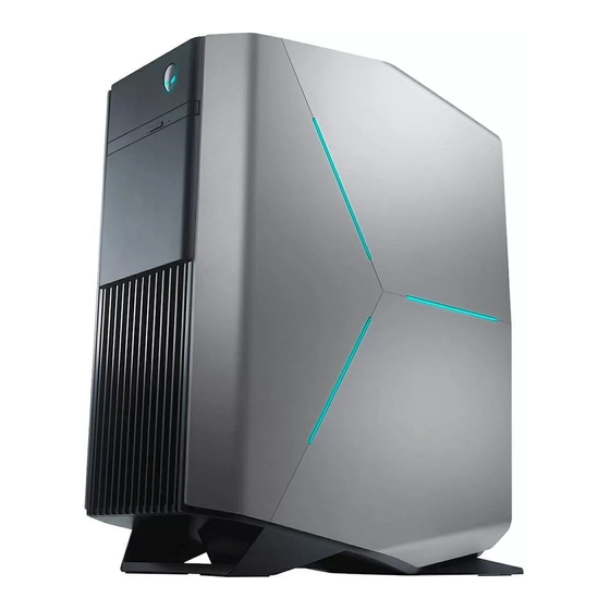
- Page 1 Aurora R6 Service Manual Regulatory Model: D23M Regulatory Type: D23M001...
- Page 2 Notes, cautions, and warnings NOTE: A NOTE indicates important information that helps you make better use of your product. CAUTION: A CAUTION indicates either potential damage to hardware or loss of data and tells you how to avoid the problem. WARNING: A WARNING indicates a potential for property damage, personal injury, or death.
-
Page 3: Table Of Contents
Contents 1 Before working inside your computer....................9 Before you begin .................................9 Safety instructions.................................9 Recommended tools................................9 Screw list..................................... 10 2 After working inside your computer....................12 3 Technical overview..........................13 Inside view of your computer............................. 13 System-board components..............................14 4 Removing the stability foot......................... 15 Procedure....................................15 5 Replacing the stability foot......................... - Page 4 Procedure................................... 27 13 Replacing the bottom cover......................29 Procedure................................... 29 Post-requisites..................................29 14 Removing the 3.5-inch hard drive....................30 Prerequisites..................................30 Procedure................................... 30 15 Replacing the 3.5-inch hard drive....................32 Procedure................................... 32 Post-requisites..................................32 16 Removing the 2.5-inch hard drive....................33 Prerequisites..................................33 Procedure...................................
- Page 5 24 Removing the processor-cooling assembly..................47 Prerequisites..................................47 Procedure................................... 47 25 Replacing the processor-cooling assembly..................50 Procedure................................... 50 Post-requisites..................................51 26 Removing the coin-cell battery......................52 Prerequisites..................................52 Procedure................................... 52 27 Replacing the coin-cell battery......................53 Procedure................................... 53 Post-requisites..................................53 28 Removing the memory modules....................... 54 Prerequisites..................................
- Page 6 Procedure................................... 63 Post-requisites..................................63 36 Removing the processor........................64 Prerequisites..................................64 Procedure................................... 64 37 Replacing the processor........................65 Procedure................................... 65 Post-requisites..................................65 38 Removing the wireless card......................66 Prerequisites..................................66 Procedure................................... 66 39 Replacing the wireless card......................67 Procedure................................... 67 Post-requisites..................................68 40 Removing the antenna........................69 Prerequisites..................................
- Page 7 47 Replacing the optical drive....................... 80 Procedure................................... 80 Post-requisites..................................80 48 Removing the front bezel ......................... 81 Prerequisites..................................81 Procedure.................................... 81 49 Replacing the front bezel........................83 Procedure................................... 83 Post-requisites..................................83 50 Removing the power-button board....................84 Prerequisites..................................84 Procedure................................... 84 51 Replacing the power-button board....................
- Page 8 Clearing CMOS Settings.............................. 99 58 Troubleshooting..........................101 Flashing the BIOS................................101 Flashing BIOS (USB key)..............................101 Enhanced Pre-Boot System Assessment (ePSA) diagnostics..................101 Running the ePSA diagnostics............................ 101 System diagnostic lights..............................102 Flea power release................................102 Wi-Fi power cycle................................102 59 Getting help and contacting Alienware..................103...
-
Page 9: Before Working Inside Your Computer
Before working inside your computer NOTE: The images in this document may differ from your computer depending on the configuration you ordered. Before you begin 1. Save and close all open files and exit all open applications. 2. Shut down your computer. Windows 10: Click or tap Start >... -
Page 10: Screw List
Screw list The following table provides the list of screws that are used for securing different components to Alienware Aurora R6. Table 1. Screw list Component Secured to Screw type Quantity Screw image 3.5-inch hard-drive cage Chassis #6-32 X 1/4'' 2.5-inch hard-drive cage... - Page 11 Component Secured to Screw type Quantity Screw image M2 X 2.5 Optical-drive bracket Optical drive M2 X 2.5 WLAN bracket System board M2 X 2.5...
-
Page 12: After Working Inside Your Computer
After working inside your computer CAUTION: Leaving stray or loose screws inside your computer may severely damage your computer. 1. Replace all screws and ensure that no stray screws remain inside your computer. 2. Connect any external devices, peripherals, or cables you removed before working on your computer. 3. -
Page 13: Technical Overview
Technical overview NOTE: Before working inside your computer, read the safety information that shipped with your computer and follow the steps in Before working inside your computer. After working inside your computer, follow the instructions in After working inside your computer. -
Page 14: System-Board Components
System-board components 1. top-chassis fan (TOP_FAN) 2. processor-cooling assembly pump-fan connector (PUMP_FAN) 3. processor-fan connector (CPU_FAN) 4. memory-module slot 1 (XMM1) 5. memory-module slot 2 (XMM2) 6. memory-module slot 3 (XMM3) 7. memory-module slot 4 (XMM4) 8. front-chassis fan connector (FRONT_FAN) 9. -
Page 15: Removing The Stability Foot
Removing the stability foot NOTE: Before working inside your computer, read the safety information that shipped with your computer and follow the steps in Before working inside your computer. After working inside your computer, follow the instructions in After working inside your computer. -
Page 16: Replacing The Stability Foot
Replacing the stability foot NOTE: Before working inside your computer, read the safety information that shipped with your computer and follow the steps in Before working inside your computer. After working inside your computer, follow the instructions in After working inside your computer. -
Page 17: Removing The Left-Side Cover
Removing the left-side cover NOTE: Before working inside your computer, read the safety information that shipped with your computer and follow the steps in Before working inside your computer. After working inside your computer, follow the instructions in After working inside your computer. -
Page 18: Replacing The Left-Side Cover
Replacing the left-side cover NOTE: Before working inside your computer, read the safety information that shipped with your computer and follow the steps in Before working inside your computer. After working inside your computer, follow the instructions in After working inside your computer. -
Page 19: Removing The Right-Side Cover
Removing the right-side cover NOTE: Before working inside your computer, read the safety information that shipped with your computer and follow the steps in Before working inside your computer. After working inside your computer, follow the instructions in After working inside your computer. - Page 20 a. right-side cover b. lighting cable...
-
Page 21: Replacing The Right-Side Cover
Replacing the right-side cover NOTE: Before working inside your computer, read the safety information that shipped with your computer and follow the steps in Before working inside your computer. After working inside your computer, follow the instructions in After working inside your computer. - Page 22 a. chassis b. slots c. right-side cover...
-
Page 23: Removing The Top-Cover Assembly
Removing the top-cover assembly NOTE: Before working inside your computer, read the safety information that shipped with your computer and follow the steps in Before working inside your computer. After working inside your computer, follow the instructions in After working inside your computer. - Page 24 1. top cover 2. slot 3. lighting cable 4. chassis 6. Turn the top cover over, release the tabs on the top cover from the slots on the top bezel. 7. Lift the top cover from the top bezel.
- Page 25 a. top cover b. top bezel 8. You are left with top bezel and top cover. a. top bezel b. top cover...
-
Page 26: Replacing The Top-Cover Assembly
Replacing the top-cover assembly NOTE: Before working inside your computer, read the safety information that shipped with your computer and follow the steps in Before working inside your computer. After working inside your computer, follow the instructions in After working inside your computer. -
Page 27: Removing The Bottom Cover
Removing the bottom cover NOTE: Before working inside your computer, read the safety information that shipped with your computer and follow the steps in Before working inside your computer. After working inside your computer, follow the instructions in After working inside your computer. - Page 28 4. Tilt the computer back to the upright position.
-
Page 29: Replacing The Bottom Cover
Replacing the bottom cover NOTE: Before working inside your computer, read the safety information that shipped with your computer and follow the steps in Before working inside your computer. After working inside your computer, follow the instructions in After working inside your computer. -
Page 30: Removing The 3.5-Inch Hard Drive
Removing the 3.5-inch hard drive NOTE: Before working inside your computer, read the safety information that shipped with your computer and follow the steps in Before working inside your computer. After working inside your computer, follow the instructions in After working inside your computer. - Page 31 a. hard drive b. hard-drive carrier c. tabs (4)
-
Page 32: Replacing The 3.5-Inch Hard Drive
Replacing the 3.5-inch hard drive NOTE: Before working inside your computer, read the safety information that shipped with your computer and follow the steps in Before working inside your computer. After working inside your computer, follow the instructions in After working inside your computer. -
Page 33: Removing The 2.5-Inch Hard Drive
Removing the 2.5-inch hard drive NOTE: Before working inside your computer, read the safety information that shipped with your computer and follow the steps in Before working inside your computer. After working inside your computer, follow the instructions in After working inside your computer. - Page 34 a. hard drive b. hard-drive carrier c. tabs (4)
-
Page 35: Replacing The 2.5-Inch Hard Drive
Replacing the 2.5-inch hard drive NOTE: Before working inside your computer, read the safety information that shipped with your computer and follow the steps in Before working inside your computer. After working inside your computer, follow the instructions in After working inside your computer. -
Page 36: Removing The U.2 Solid-State Drive
Removing the U.2 solid-state drive NOTE: Before working inside your computer, read the safety information that shipped with your computer and follow the steps in Before working inside your computer. After working inside your computer, follow the instructions in After working inside your computer. - Page 37 5. hard-drive carrier 11. Remove the tabs U.2 solid-state drive from the slots on the hard-drive carrier and lift the U.2 solid-state drive. a. hard-drive carrier b. fan cable c. U.2 solid-state drive...
-
Page 38: Replacing The U.2 Solid-State Drive
Replacing the U.2 solid-state drive NOTE: Before working inside your computer, read the safety information that shipped with your computer and follow the steps in Before working inside your computer. After working inside your computer, follow the instructions in After working inside your computer. -
Page 39: Post-Requisites
1. solid-state drive slot 2. screw 3. data cable 4. solid-state drive adapter 5. power cable 6. fan cable 7. Rotate the power-supply unit cage towards the chassis until the unit snaps into place. 8. Connect the power cable to the U.2 solid-state drive. a. -
Page 40: Removing The Hard-Drive Cage
Removing the hard-drive cage NOTE: Before working inside your computer, read the safety information that shipped with your computer and follow the steps in Before working inside your computer. After working inside your computer, follow the instructions in After working inside your computer. -
Page 41: Replacing The Hard-Drive Cage
Replacing the hard-drive cage NOTE: Before working inside your computer, read the safety information that shipped with your computer and follow the steps in Before working inside your computer. After working inside your computer, follow the instructions in After working inside your computer. -
Page 42: Removing The Power-Supply Unit
Removing the power-supply unit NOTE: Before working inside your computer, read the safety information that shipped with your computer and follow the steps in Before working inside your computer. After working inside your computer, follow the instructions in After working inside your computer. - Page 43 a. power-supply unit cage b. graphics-card bracket c. chassis 4. Rotate the power-supply unit cage away from the chassis. a. power-supply unit 5. Press the releasing clip on the power-cable connectors and disconnect the power cables from the graphics card. 6.
- Page 44 7. Disconnect the processor-power cable and system-board power cable from the system board. 1. power-supply unit 2. hard-drive power cable 3. graphics-card power cables (2) 4. releasing clips (2) 5. hard-drive power cable 6. processor-power cable 7. optical-drive power cable 8.
- Page 45 12. Lift the power-supply unit, along with the cables, off the chassis. a. chassis b. power-supply unit c. screws (4)
-
Page 46: Replacing The Power-Supply Unit
Replacing the power-supply unit NOTE: Before working inside your computer, read the safety information that shipped with your computer and follow the steps in Before working inside your computer. After working inside your computer, follow the instructions in After working inside your computer. -
Page 47: Removing The Processor-Cooling Assembly
Removing the processor-cooling assembly NOTE: Before working inside your computer, read the safety information that shipped with your computer and follow the steps in Before working inside your computer. After working inside your computer, follow the instructions in After working inside your computer. - Page 48 a. captive screws (2) b. VR heat sink 5. Disconnect the processor-cooling assembly cables from the system board. 6. In reversed order (as indicated on the processor cooler), loosen the captive screws that secure the processor cooler to the system board.
- Page 49 1. radiator fan 2. radiator-fan cable 3. system board 4. processor-cooling assembly cable 5. captive screws (4)
-
Page 50: Replacing The Processor-Cooling Assembly
Replacing the processor-cooling assembly NOTE: Before working inside your computer, read the safety information that shipped with your computer and follow the steps in Before working inside your computer. After working inside your computer, follow the instructions in After working inside your computer. -
Page 51: Post-Requisites
a. VR heat sink b. captive screws (2) c. system board 9. Follow the procedure from step 10 to step 11 in "Replacing the power-supply unit". 10. Replace the screws that secure the radiator and fan assembly to the chassis. Post-requisites 1. -
Page 52: Removing The Coin-Cell Battery
Removing the coin-cell battery NOTE: Before working inside your computer, read the safety information that shipped with your computer and follow the steps in Before working inside your computer. After working inside your computer, follow the instructions in After working inside your computer. -
Page 53: Replacing The Coin-Cell Battery
Replacing the coin-cell battery NOTE: Before working inside your computer, read the safety information that shipped with your computer and follow the steps in Before working inside your computer. After working inside your computer, follow the instructions in After working inside your computer. -
Page 54: Removing The Memory Modules
Removing the memory modules NOTE: Before working inside your computer, read the safety information that shipped with your computer and follow the steps in Before working inside your computer. After working inside your computer, follow the instructions in After working inside your computer. -
Page 55: Replacing The Memory Modules
Replacing the memory modules NOTE: Before working inside your computer, read the safety information that shipped with your computer and follow the steps in Before working inside your computer. After working inside your computer, follow the instructions in After working inside your computer. -
Page 56: Post-Requisites
Slot Configuration DIMM1 DIMM2 DIMM3 DIMM4 32 GB DDR4 8 GB 8 GB 8 GB 8 GB 64 GB DDR4 16 GB 16 GB 16 GB 16 GB 8 GB XMP 4 GB 4 GB 16 GB XMP 8 GB 8 GB Post-requisites 1. -
Page 57: Removing The Solid-State Drive
Removing the solid-state drive NOTE: Before working inside your computer, read the safety information that shipped with your computer and follow the steps in Before working inside your computer. After working inside your computer, follow the instructions in After working inside your computer. -
Page 58: Replacing The Solid-State Drive
Replacing the solid-state drive NOTE: Before working inside your computer, read the safety information that shipped with your computer and follow the steps in Before working inside your computer. After working inside your computer, follow the instructions in After working inside your computer. -
Page 59: Removing The Graphics Card
Removing the graphics card NOTE: Before working inside your computer, read the safety information that shipped with your computer and follow the steps in Before working inside your computer. After working inside your computer, follow the instructions in After working inside your computer. - Page 60 1. power cables 2. releasing clips (2) 3. graphics card 4. securing tab...
-
Page 61: Replacing The Graphics Card
Replacing the graphics card NOTE: Before working inside your computer, read the safety information that shipped with your computer and follow the steps in Before working inside your computer. After working inside your computer, follow the instructions in After working inside your computer. -
Page 62: Removing The Processor Fan And Heat-Sink Assembly
Removing the processor fan and heat-sink assembly NOTE: Before working inside your computer, read the safety information that shipped with your computer and follow the steps in Before working inside your computer. After working inside your computer, follow the instructions in After working inside your computer. -
Page 63: Replacing The Processor Fan And Heat-Sink Assembly
Replacing the processor fan and heat-sink assembly NOTE: Before working inside your computer, read the safety information that shipped with your computer and follow the steps in Before working inside your computer. After working inside your computer, follow the instructions in After working inside your computer. -
Page 64: Removing The Processor
Removing the processor NOTE: Before working inside your computer, read the safety information that shipped with your computer and follow the steps in Before working inside your computer. After working inside your computer, follow the instructions in After working inside your computer. -
Page 65: Replacing The Processor
Replacing the processor NOTE: Before working inside your computer, read the safety information that shipped with your computer and follow the steps in Before working inside your computer. After working inside your computer, follow the instructions in After working inside your computer. -
Page 66: Removing The Wireless Card
Removing the wireless card NOTE: Before working inside your computer, read the safety information that shipped with your computer and follow the steps in Before working inside your computer. After working inside your computer, follow the instructions in After working inside your computer. -
Page 67: Replacing The Wireless Card
Replacing the wireless card NOTE: Before working inside your computer, read the safety information that shipped with your computer and follow the steps in Before working inside your computer. After working inside your computer, follow the instructions in After working inside your computer. -
Page 68: Post-Requisites
Post-requisites 1. Follow the procedure from step 10 to step 11 in "Replacing the power-supply unit". 2. Replace the left-side cover. -
Page 69: Removing The Antenna
Removing the antenna NOTE: Before working inside your computer, read the safety information that shipped with your computer and follow the steps in Before working inside your computer. After working inside your computer, follow the instructions in After working inside your computer. - Page 70 a. antenna b. antenna cables c. routing guides...
-
Page 71: Replacing The Antenna
Replacing the antenna NOTE: Before working inside your computer, read the safety information that shipped with your computer and follow the steps in Before working inside your computer. After working inside your computer, follow the instructions in After working inside your computer. -
Page 72: Removing The Front-Chassis Fan
Removing the front-chassis fan NOTE: Before working inside your computer, read the safety information that shipped with your computer and follow the steps in Before working inside your computer. After working inside your computer, follow the instructions in After working inside your computer. - Page 73 a. front-chassis fan cable b. front-chassis fan bracket c. front-chassis fan...
-
Page 74: Replacing The Front-Chassis Fan
Replacing the front-chassis fan NOTE: Before working inside your computer, read the safety information that shipped with your computer and follow the steps in Before working inside your computer. After working inside your computer, follow the instructions in After working inside your computer. -
Page 75: Removing The Top-Chassis Fan
Removing the top-chassis fan NOTE: Before working inside your computer, read the safety information that shipped with your computer and follow the steps in Before working inside your computer. After working inside your computer, follow the instructions in After working inside your computer. - Page 76 1. top-chassis fan cable 2. routing guide 3. rubber grommets (4) 4. top-chassis fan bracket 5. top-chassis fan...
-
Page 77: Replacing The Top-Chassis Fan
Replacing the top-chassis fan NOTE: Before working inside your computer, read the safety information that shipped with your computer and follow the steps in Before working inside your computer. After working inside your computer, follow the instructions in After working inside your computer. -
Page 78: Removing The Optical Drive
Removing the optical drive NOTE: Before working inside your computer, read the safety information that shipped with your computer and follow the steps in Before working inside your computer. After working inside your computer, follow the instructions in After working inside your computer. - Page 79 a. optical-drive assembly b. chassis 4. Remove the screw that secures the optical-drive bracket to the optical drive. a. screw b. optical-drive bracket c. optical drive 5. Gently pull and disconnect the optical-drive bezel from the optical drive. a. optical drive b.
-
Page 80: Replacing The Optical Drive
Replacing the optical drive NOTE: Before working inside your computer, read the safety information that shipped with your computer and follow the steps in Before working inside your computer. After working inside your computer, follow the instructions in After working inside your computer. -
Page 81: Removing The Front Bezel
Removing the front bezel NOTE: Before working inside your computer, read the safety information that shipped with your computer and follow the steps in Before working inside your computer. After working inside your computer, follow the instructions in After working inside your computer. - Page 82 a. chassis b. tabs c. front bezel...
-
Page 83: Replacing The Front Bezel
Replacing the front bezel NOTE: Before working inside your computer, read the safety information that shipped with your computer and follow the steps in Before working inside your computer. After working inside your computer, follow the instructions in After working inside your computer. -
Page 84: Removing The Power-Button Board
Removing the power-button board NOTE: Before working inside your computer, read the safety information that shipped with your computer and follow the steps in Before working inside your computer. After working inside your computer, follow the instructions in After working inside your computer. -
Page 85: Replacing The Power-Button Board
Replacing the power-button board NOTE: Before working inside your computer, read the safety information that shipped with your computer and follow the steps in Before working inside your computer. After working inside your computer, follow the instructions in After working inside your computer. -
Page 86: Removing The Rear Trim Cover
Removing the rear trim cover NOTE: Before working inside your computer, read the safety information that shipped with your computer and follow the steps in Before working inside your computer. After working inside your computer, follow the instructions in After working inside your computer. -
Page 87: Replacing The Rear Trim Cover
Replacing the rear trim cover NOTE: Before working inside your computer, read the safety information that shipped with your computer and follow the steps in Before working inside your computer. After working inside your computer, follow the instructions in After working inside your computer. -
Page 88: Removing The System Board
Removing the system board NOTE: Before working inside your computer, read the safety information that shipped with your computer and follow the steps in Before working inside your computer. After working inside your computer, follow the instructions in After working inside your computer. - Page 89 1. Top panel USB cables (SSUSB) 2. SATA 6 Gbps drive cable (SATA1) 3. SATA 6 Gbps drive cable (SATA2) 4. system board 5. front-panel audio cable (F_AUDIO) 6. LED controller cable (LED_CONTROLLER) 7. graphics-card power cable (GPU_POWER) 8. processor power cable (ATX_CPU) 9.
- Page 90 a. chassis b. system board c. screws (8)
-
Page 91: Replacing The System Board
Replacing the system board NOTE: Before working inside your computer, read the safety information that shipped with your computer and follow the steps in Before working inside your computer. After working inside your computer, follow the instructions in After working inside your computer. -
Page 92: Downloading Drivers
Downloading drivers Downloading the audio driver 1. Turn on your computer. 2. Go to www.dell.com/support. 3. Click Product support, enter the Service Tag of your computer and then click Submit. NOTE: If you do not have the Service Tag, use the auto-detect feature or manually browse for your computer model. 4. -
Page 93: Downloading The Network Driver
Downloading the network driver 1. Turn on your computer. 2. Go to www.dell.com/support. 3. Click Product support, enter the Service Tag of your computer, and then click Submit. NOTE: If you do not have the Service Tag, use the auto-detect feature or manually browse for your computer model. 4. -
Page 94: System Setup
System setup NOTE: Depending on the computer and its installed devices, the items listed in this section may or may not be displayed. Boot Sequence Boot Sequence allows you to bypass the System Setup–defined boot device order and boot directly to a specific device (for example: optical drive or hard drive). -
Page 95: Bios Features
BIOS Information BIOS Version Displays the BIOS version number. Product Information Product Name Displays the product name. Default: Alienware Aurora R6. Service Tag Displays the service tag of your computer. Asset Tag Displays the asset tag of your computer. Memory Information System Memory Displays the total computer memory installed. - Page 96 Advanced Intel SpeedStep Allows you to enable or disable Intel Speedstep Technology. Default: Enabled. NOTE: If enabled, the processor clock speed and core voltage are adjusted dynamically based on the processor load. Virtualization Allows you to enable or disable Intel Virtualization Technology feature for the processor.
- Page 97 Advanced Core Ratio Limit Override Allows you to set the core ratio limit. Single Core Allows you to select single core or multiple cores. Core Voltage Mode Allows you to select between adaptive and override voltage modes. Core Voltage Offset Allows you to set the override value of core voltage.
-
Page 98: System And Setup Password
System and setup password You can create a system password and a setup password to secure your computer. Password type Description System password Password that you must enter to log on to your system. Setup password Password that you must enter to access and make changes to the BIOS settings of your computer. CAUTION: The password features provide a basic level of security for the data on your computer. -
Page 99: Clearing Cmos Settings
Prerequisites 1. Remove the left-side cover. 2. Follow the procedure from step 1 to step 4 in "Removing the power-supply unit". Procedure 1. Locate the password jumper (P215) on the system board. For information on the location of the Password jumper, see System-board components. - Page 100 Prerequisites 1. Remove the left-side cover. 2. Follow the procedure from step 1 to step 4 in "Removing the power-supply unit". Procedure 1. Locate the CMOS jumper (P217) on the system board. For information on the location of the CMOS jumper, see "System-board components".
-
Page 101: Troubleshooting
Troubleshooting Flashing the BIOS You may need to flash (update) the BIOS when an update is available or when you replace the system board. Follow these steps to flash the BIOS: 1. Turn on your computer. 2. Go to www.dell.com/support. 3. -
Page 102: System Diagnostic Lights
Diagnostics front page is displayed. 5. Press the arrow in the lower-right corner to go to the page listing. The items detected are listed. 6. To run a diagnostic test on a specific device, press Esc and click Yes to stop the diagnostic test. 7. -
Page 103: Getting Help And Contacting Alienware
Getting help and contacting Alienware Self-help resources You can get information and help on Alienware products and services using these online self-help resources: Table 10. Self-help resources Information about Alienware products and services www.alienware.com Troubleshooting information, user manuals, setup instructions, www.alienware.com/gamingservices...