
Related Manuals for Bosch Rexroth IndraControl L25


Summary of Contents for Bosch Rexroth IndraControl L25
- Page 1 Electric Drives Linear Motion and and Controls Hydraulics Assembly Technologies Pneumatics Service Rexroth IndraControl R911336525 Edition 01 L25, L45, L65 and l85 Controls Instructions...
- Page 2 © Bosch Rexroth AG 2012 This document, as well as the data, specifications and other information set forth in it, are the exclusive property of Bosch Rexroth AG. It may not be re‐ produced or given to third parties without its consent.
-
Page 3: Table Of Contents
DOK-CONTRL-IC*LX5*****-IT01-EN-P Bosch Rexroth AG I/65 Rexroth IndraControl L25, L45, L65 and L85 Controls Table of Contents Table of Contents Page About this Documentation....................5 Product Identification and Scope of Delivery..............7 Product Identification..........................7 Scope of Delivery............................ 7 Using the Safety Instructions..................9 Safety instructions –... - Page 4 II/65 Bosch Rexroth AG DOK-CONTRL-IC*LX5*****-IT01-EN-P Rexroth IndraControl L25, L45, L65 and L85 Controls Table of Contents Page 10.5 Dismounting the Control........................34 10.6 Dismounting and changing the Inline terminals..................36 10.7 Electrical Installation..........................38 10.7.1 General Information........................... 38 10.7.2 External Power Supply Unit ......................38 10.7.3...
- Page 5 DOK-CONTRL-IC*LX5*****-IT01-EN-P Bosch Rexroth AG III/65 Rexroth IndraControl L25, L45, L65 and L85 Controls Table of Contents Page Service and Support....................61 Index..........................63...
- Page 6 IV/65 Bosch Rexroth AG DOK-CONTRL-IC*LX5*****-IT01-EN-P Rexroth IndraControl L25, L45, L65 and L85 Controls...
-
Page 7: About This Documentation
DOK-CONTRL-IC*LX5*****-IT01-EN-P Bosch Rexroth AG 5/65 Rexroth IndraControl L25, L45, L65 and L85 Controls About this Documentation About this Documentation The activities, product phases and target groups that refer to the present doc‐ Overview – target groups and product phases umentation are marked in red color in the following figure. - Page 8 6/65 Bosch Rexroth AG DOK-CONTRL-IC*LX5*****-IT01-EN-P Rexroth IndraControl L25, L45, L65 and L85 Controls About this Documentation Further documents Title Code (part short text) and Parts number type of documentation PLC Programming with DOK-CONTRL- R911305036 Rexroth IndraLogic 1.0 IL**PRO*V01-AWxx-EN-P Operating and Programming...
-
Page 9: Product Identification And Scope Of Delivery
DOK-CONTRL-IC*LX5*****-IT01-EN-P Bosch Rexroth AG 7/65 Rexroth IndraControl L25, L45, L65 and L85 Controls Product Identification and Scope of Delivery Product Identification and Scope of Delivery Product Identification The type plate is located on the back side. 13026 7261 BTV40.1AHB-256S-P5C- UN-FW... - Page 10 8/65 Bosch Rexroth AG DOK-CONTRL-IC*LX5*****-IT01-EN-P Rexroth IndraControl L25, L45, L65 and L85 Controls...
-
Page 11: Using The Safety Instructions
DOK-CONTRL-IC*LX5*****-IT01-EN-P Bosch Rexroth AG 9/65 Rexroth IndraControl L25, L45, L65 and L85 Controls Using the Safety Instructions Using the Safety Instructions Safety instructions – structure The safety instructions are structured as follows: Safety alert symbol Consequences and source of danger... - Page 12 10/65 Bosch Rexroth AG DOK-CONTRL-IC*LX5*****-IT01-EN-P Rexroth IndraControl L25, L45, L65 and L85 Controls...
-
Page 13: Intended Use
DOK-CONTRL-IC*LX5*****-IT01-EN-P Bosch Rexroth AG 11/65 Rexroth IndraControl L25, L45, L65 and L85 Controls Intended Use Intended Use Danger of destruction of the device if not ex‐ NOTICE pressly stated accessories, mounting parts and other components, cables, lines, soft‐ ware and firmware are used. - Page 14 12/65 Bosch Rexroth AG DOK-CONTRL-IC*LX5*****-IT01-EN-P Rexroth IndraControl L25, L45, L65 and L85 Controls...
-
Page 15: Spare Parts, Accessories, And Wear Parts
DOK-CONTRL-IC*LX5*****-IT01-EN-P Bosch Rexroth AG 13/65 Rexroth IndraControl L25, L45, L65 and L85 Controls Spare Parts, Accessories, and Wear Parts Spare Parts, Accessories, and Wear Parts Connector Set for the L45, L65, L85 Control Order code Parts number Description R-IB IL CML S01 PLSET R911299856 2 input, 2 output and 1 power con‐... -
Page 16: Power Supply Unit
14/65 Bosch Rexroth AG DOK-CONTRL-IC*LX5*****-IT01-EN-P Rexroth IndraControl L25, L45, L65 and L85 Controls Spare Parts, Accessories, and Wear Parts Power Supply Unit Order code Parts number Description VAP01.1H-W23-024-010-NN R911171065 24 V power supply unit Fig.5-7: Power supply unit Wear Parts Wear parts are not subject to any warranty. -
Page 17: Ambient Conditions
DOK-CONTRL-IC*LX5*****-IT01-EN-P Bosch Rexroth AG 15/65 Rexroth IndraControl L25, L45, L65 and L85 Controls Ambient Conditions Ambient Conditions In operation Transport Storage Max. surrounding +5 ℃ to +55 ℃ -25 ℃ to +70 ℃ -25 ℃ to +70 ℃ air temperature Relative humidity RH -2;... - Page 18 16/65 Bosch Rexroth AG DOK-CONTRL-IC*LX5*****-IT01-EN-P Rexroth IndraControl L25, L45, L65 and L85 Controls Ambient Conditions Use the "IH_Temperature" function to read out the internal control tempera‐ ture in the "RIH_CMLx.library" library of the "IndraWorks" application program (from version 11), see also documentation Rexroth IndraWorks 12VRS Basic Libraries IndraLogic 2G, ( DOK-IL*2G*-BASLIB**V12-LI01-EN-P, parts num‐...
-
Page 19: Technical Data
DOK-CONTRL-IC*LX5*****-IT01-EN-P Bosch Rexroth AG 17/65 Rexroth IndraControl L25, L45, L65 and L85 Controls Technical Data Technical Data Processor Control L25: Renesas SH7785 with 576 MHz (CPU CLK) Control L45: AMD LX800 with 500 MHz Control L65: Intel Celeron M with 1.0 GHz Control L85: Intel Core2Duo with 1.2 GHz... - Page 20 18/65 Bosch Rexroth AG DOK-CONTRL-IC*LX5*****-IT01-EN-P Rexroth IndraControl L25, L45, L65 and L85 Controls Technical Data Degree of protection IP 20 Dimensions chapter 10.2 "Housing Dimensions" on page 26 Fig.7-1: Technical data Voltage supply and current, power The control is supplied with 24 V. The following values according to...
-
Page 21: Standards
DOK-CONTRL-IC*LX5*****-IT01-EN-P Bosch Rexroth AG 19/65 Rexroth IndraControl L25, L45, L65 and L85 Controls Standards Standards Used Standards Standard Description DIN EN 60 204-1 Electrical equipment of machines DIN EN 61 131-2 Programmable logic controllers Equipment and tests requirements DIN EN 60 529 Degrees of protection (including housings and installa‐... - Page 22 20/65 Bosch Rexroth AG DOK-CONTRL-IC*LX5*****-IT01-EN-P Rexroth IndraControl L25, L45, L65 and L85 Controls Standards ● C22.2 no. 142-M1987 (CSA) However, there can be combinations or extension stages with limited or miss‐ ing certification. Thus, verify the certification by using the UL marking on the device.
-
Page 23: Interfaces
DOK-CONTRL-IC*LX5*****-IT01-EN-P Bosch Rexroth AG 21/65 Rexroth IndraControl L25, L45, L65 and L85 Controls Interfaces Interfaces Interface View ① to ⑩ fig. 9-2 "Overview, interfaces of the control" on page 22 ⑦ Slot for Compact Flash card ⑪ PWR IN voltage supply Fig.9-1:... -
Page 24: Overview
22/65 Bosch Rexroth AG DOK-CONTRL-IC*LX5*****-IT01-EN-P Rexroth IndraControl L25, L45, L65 and L85 Controls Interfaces Overview Designa‐ Connection type Connector Mating Notes on device var‐ tion at the type connector iants housing and cable (integra‐ (no. in the ted) (from out‐... - Page 25 DOK-CONTRL-IC*LX5*****-IT01-EN-P Bosch Rexroth AG 23/65 Rexroth IndraControl L25, L45, L65 and L85 Controls Interfaces Designa‐ Connection type Connector Mating Notes on device var‐ tion at the type connector iants housing and cable (integra‐ (no. in the ted) (from out‐ graphic)
- Page 26 24/65 Bosch Rexroth AG DOK-CONTRL-IC*LX5*****-IT01-EN-P Rexroth IndraControl L25, L45, L65 and L85 Controls...
-
Page 27: Mounting, Dismounting And Electrical Installation
DOK-CONTRL-IC*LX5*****-IT01-EN-P Bosch Rexroth AG 25/65 Rexroth IndraControl L25, L45, L65 and L85 Controls Mounting, Dismounting and Electrical Installation Mounting, Dismounting and Electrical Installation 10.1 Installation Notes ● Do not lay the cables in parallel to motor cables or other strong sources of interference over longer distances as otherwise interference could be coupled in. -
Page 28: Housing Dimensions
26/65 Bosch Rexroth AG DOK-CONTRL-IC*LX5*****-IT01-EN-P Rexroth IndraControl L25, L45, L65 and L85 Controls Mounting, Dismounting and Electrical Installation 10.2 Housing Dimensions Housing dimensions L45, L65 (without fan) Fig.10-2: L45, L65 (without fan), bottom view (in mm) Fig.10-3: L45, L65 (without fan), front view (in mm) - Page 29 DOK-CONTRL-IC*LX5*****-IT01-EN-P Bosch Rexroth AG 27/65 Rexroth IndraControl L25, L45, L65 and L85 Controls Mounting, Dismounting and Electrical Installation Fig.10-4: L45, L65 (without fan), left view (in mm), the cut-out for the top-hat rail is arranged centrally Housing dimensions L45, L65 and L85 (with fan) Fig.10-5:...
- Page 30 28/65 Bosch Rexroth AG DOK-CONTRL-IC*LX5*****-IT01-EN-P Rexroth IndraControl L25, L45, L65 and L85 Controls Mounting, Dismounting and Electrical Installation Fig.10-6: L45, L65 and L85 (with fan), front view (in mm) Fig.10-7: L45, L65 and L85 (with fan), left view (in mm), the cut-out for the top-...
- Page 31 DOK-CONTRL-IC*LX5*****-IT01-EN-P Bosch Rexroth AG 29/65 Rexroth IndraControl L25, L45, L65 and L85 Controls Mounting, Dismounting and Electrical Installation Housing dimensions L25 Fig.10-8: L25, bottom view (in mm) Fig.10-9: L25, front view (in mm)
-
Page 32: Mounting The Control
30/65 Bosch Rexroth AG DOK-CONTRL-IC*LX5*****-IT01-EN-P Rexroth IndraControl L25, L45, L65 and L85 Controls Mounting, Dismounting and Electrical Installation Fig.10-10: L25, left view (in mm), the cut-out for the top-hat rail is arranged cen‐ trally Housing dimensions of the fan Fig.10-11: Fan, front view (in mm) 10.3... - Page 33 DOK-CONTRL-IC*LX5*****-IT01-EN-P Bosch Rexroth AG 31/65 Rexroth IndraControl L25, L45, L65 and L85 Controls Mounting, Dismounting and Electrical Installation Possible damage to property due to improper NOTICE mounting of the top-hat rail ● Fasten the top-hat rail adequately. ● Connect the top-hat rail to a functional ground.
- Page 34 32/65 Bosch Rexroth AG DOK-CONTRL-IC*LX5*****-IT01-EN-P Rexroth IndraControl L25, L45, L65 and L85 Controls Mounting, Dismounting and Electrical Installation Fig.10-13: Latching the terminal on top-hat rail Ensure that all feather keys and keyways of neighboring terminals are interlocked (B in 10-13).
- Page 35 DOK-CONTRL-IC*LX5*****-IT01-EN-P Bosch Rexroth AG 33/65 Rexroth IndraControl L25, L45, L65 and L85 Controls Mounting, Dismounting and Electrical Installation Production failure possible due to con‐ NOTICE trol failure resulting from a missing EMI shielding. Mount the shielding at the right end of the control in order to protect the control from ESD pulses.
-
Page 36: Mounting The Fan (If Necessary)
34/65 Bosch Rexroth AG DOK-CONTRL-IC*LX5*****-IT01-EN-P Rexroth IndraControl L25, L45, L65 and L85 Controls Mounting, Dismounting and Electrical Installation 10.4 Mounting the Fan (if Necessary) ① Control bottom side ② Fig.10-16: Mounting the fan 1. Put the fan ② onto the control ①, see 10-16. - Page 37 DOK-CONTRL-IC*LX5*****-IT01-EN-P Bosch Rexroth AG 35/65 Rexroth IndraControl L25, L45, L65 and L85 Controls Mounting, Dismounting and Electrical Installation Fig.10-17: Remove the labeling field, removing the connectors Remove the connectors (B in 10-17). Remove the power connector from the control. This ensures that the feathers of the voltage jumpers and the keyway/ feather key connection are prevented from damage.
-
Page 38: Dismounting And Changing The Inline Terminals
36/65 Bosch Rexroth AG DOK-CONTRL-IC*LX5*****-IT01-EN-P Rexroth IndraControl L25, L45, L65 and L85 Controls Mounting, Dismounting and Electrical Installation ① Release lever Fig.10-19: Position of the release lever Tilt the control upwards (C in 10-20). Fig.10-20: Dismounting the control from the top-hat rail Remove the control by pulling it diagonally upwards (C in 10-20). - Page 39 DOK-CONTRL-IC*LX5*****-IT01-EN-P Bosch Rexroth AG 37/65 Rexroth IndraControl L25, L45, L65 and L85 Controls Mounting, Dismounting and Electrical Installation Fig.10-21: Remove the labeling field, removing the connectors Remove the connector (B in 10-21). Remove the adjacent connectors of the neighboring terminals (C in 10-22).
-
Page 40: Electrical Installation
38/65 Bosch Rexroth AG DOK-CONTRL-IC*LX5*****-IT01-EN-P Rexroth IndraControl L25, L45, L65 and L85 Controls Mounting, Dismounting and Electrical Installation 10.7 Electrical Installation 10.7.1 General Information Danger of personal injury due to wrong instal‐ WARNING lation or due to wrong electrical installation! ●... - Page 41 DOK-CONTRL-IC*LX5*****-IT01-EN-P Bosch Rexroth AG 39/65 Rexroth IndraControl L25, L45, L65 and L85 Controls Mounting, Dismounting and Electrical Installation Power connector for the controls ① Power connector for the control L45, L65 and L85 from the connector set "R-IB IL CML S01-PLSET"...
-
Page 42: Voltage Supply
40/65 Bosch Rexroth AG DOK-CONTRL-IC*LX5*****-IT01-EN-P Rexroth IndraControl L25, L45, L65 and L85 Controls Mounting, Dismounting and Electrical Installation 10.7.4 24 V Voltage Supply 24 V voltage supply The 24 V voltage supply can either be realized with or without electrical isola‐... -
Page 43: Grounding
DOK-CONTRL-IC*LX5*****-IT01-EN-P Bosch Rexroth AG 41/65 Rexroth IndraControl L25, L45, L65 and L85 Controls Mounting, Dismounting and Electrical Installation Logic power supply unit Load power supply unit 0 V 24 V 0 V 24 V 1.1 2.1 1.2 2.2 Overvoltage category I 24 V 1.3 2.3... -
Page 44: Shielding
42/65 Bosch Rexroth AG DOK-CONTRL-IC*LX5*****-IT01-EN-P Rexroth IndraControl L25, L45, L65 and L85 Controls Mounting, Dismounting and Electrical Installation ① Grounding screw Fig.10-27: Grounding screw, position Recommended value: Length: Max. 1 m, cross-section 6 mm The functional earth ground (FE) is used for discharging disturbances. It is not provided as a protection against electric shock for persons. -
Page 45: Notice For Use Of The Control Above 2700 M Above Msl
60204 (see also chapter 6 "Ambient Conditions" on page 15). If it is used above 2700 m above MSL, Bosch Rexroth cannot as‐ sume warranty. Therefore the user assumes responsibility if it used above 2700 m above MSL. To realize use above 2700 m above MSL, nevertheless, the user has to take appropriate measures, particularly the track resistance has to be ensured. -
Page 46: Digital Onboard Inputs On Controls L45, L65 And L85
44/65 Bosch Rexroth AG DOK-CONTRL-IC*LX5*****-IT01-EN-P Rexroth IndraControl L25, L45, L65 and L85 Controls Mounting, Dismounting and Electrical Installation ● Use the "VAP01.1H-W23 024-010-NN" Bosch Rexroth power supply unit to generate the DC 24 V supply voltage, parts number R911171065. Circuit proposal More detailed information on the wiring is contained in the power supply unit documentation. -
Page 47: Digital Onboard Outputs On Controls L45, L65 And L85
DOK-CONTRL-IC*LX5*****-IT01-EN-P Bosch Rexroth AG 45/65 Rexroth IndraControl L25, L45, L65 and L85 Controls Mounting, Dismounting and Electrical Installation 10.7.10 Digital Onboard Outputs on Controls L45, L65 and L85 Between the digital inputs and the power terminals, a total of eight digital out‐... -
Page 48: Further Interfaces
46/65 Bosch Rexroth AG DOK-CONTRL-IC*LX5*****-IT01-EN-P Rexroth IndraControl L25, L45, L65 and L85 Controls Mounting, Dismounting and Electrical Installation Destruction of the device due to improper NOTICE connection If connected improperly, the device might be destroyed. For that reason, avoid: ●... -
Page 49: Commissioning
DOK-CONTRL-IC*LX5*****-IT01-EN-P Bosch Rexroth AG 47/65 Rexroth IndraControl L25, L45, L65 and L85 Controls Commissioning Commissioning General Information Production failure due to uncontrolled ma‐ NOTICE chine movement, caused by operation with‐ out Compact Flash card or by removal of the Compact Flash card during operation. - Page 50 48/65 Bosch Rexroth AG DOK-CONTRL-IC*LX5*****-IT01-EN-P Rexroth IndraControl L25, L45, L65 and L85 Controls...
-
Page 51: Device Description
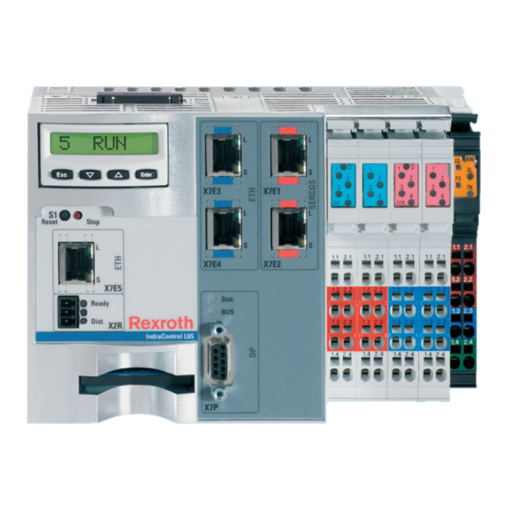
DOK-CONTRL-IC*LX5*****-IT01-EN-P Bosch Rexroth AG 49/65 Rexroth IndraControl L25, L45, L65 and L85 Controls Device Description Device Description 12.1 General Information Fig.12-1: Front view of a control (here: L45, L65) 12.2 Display Elements General information on the display On its front, the control is provided with the following display and operating... -
Page 52
50/65 Bosch Rexroth AG DOK-CONTRL-IC*LX5*****-IT01-EN-P Rexroth IndraControl L25, L45, L65 and L85 Controls Device Description Menu navigation Input functions
One menu entry up Increase parameter value (up arrow) One level down Confirm input Fig.12-3: Functions of the operating keys Reset button and stop LED on the The reset button and a red LED are arranged in the section below the dis‐... -
Page 53: Error Causes And Error Elemination
DOK-CONTRL-IC*LX5*****-IT01-EN-P Bosch Rexroth AG 51/65 Rexroth IndraControl L25, L45, L65 and L85 Controls Error Causes and Error Elemination Error Causes and Error Elemination "System is booting" and "No Com‐ pact Flash" displays The "System is booting" and "No Compact Flash" displays directly refer to the control while other displays are system-specific. - Page 54 52/65 Bosch Rexroth AG DOK-CONTRL-IC*LX5*****-IT01-EN-P Rexroth IndraControl L25, L45, L65 and L85 Controls...
-
Page 55: Maintenance
Maintenance work in the device is only per‐ NOTICE missible by skilled staff! If hardware or software components have to be exchanged, please contact the Bosch Rexroth Service or ensure that only skilled staff changes the re‐ spective components. 14.2 Regular Maintenance Include the following measures in the maintenance schedule: ●... - Page 56 54/65 Bosch Rexroth AG DOK-CONTRL-IC*LX5*****-IT01-EN-P Rexroth IndraControl L25, L45, L65 and L85 Controls Maintenance ① Battery case at the control Fig.14-1: Use the plastic strip to pull the battery out of the housing. To insert a new battery, pull the battery cover forward using the plastic strap attached thereon (see ②...
-
Page 57: Ordering Information
DOK-CONTRL-IC*LX5*****-IT01-EN-P Bosch Rexroth AG 55/65 Rexroth IndraControl L25, L45, L65 and L85 Controls Ordering Information Ordering Information 15.1 Accessories and Spare Parts Ordering information for accessories and spare parts is available in chapter 5 "Spare Parts, Accessories, and Wear Parts" on page 15.2... -
Page 58: Type Designation Code L45
56/65 Bosch Rexroth AG DOK-CONTRL-IC*LX5*****-IT01-EN-P Rexroth IndraControl L25, L45, L65 and L85 Controls Ordering Information 15.3 Type Designation Code L45 Fig.15-2: Type designation code L45... -
Page 59: Type Designation Code L65
DOK-CONTRL-IC*LX5*****-IT01-EN-P Bosch Rexroth AG 57/65 Rexroth IndraControl L25, L45, L65 and L85 Controls Ordering Information 15.4 Type Designation Code L65 Fig.15-3: Type designation code L65... -
Page 60: Type Designation Code L85
58/65 Bosch Rexroth AG DOK-CONTRL-IC*LX5*****-IT01-EN-P Rexroth IndraControl L25, L45, L65 and L85 Controls Ordering Information 15.5 Type Designation Code L85 Fig.15-4: Type designation code L85... -
Page 61: Disposal
DOK-CONTRL-IC*LX5*****-IT01-EN-P Bosch Rexroth AG 59/65 Rexroth IndraControl L25, L45, L65 and L85 Controls Disposal Disposal 16.1 General Information Dispose the products according to the respective national standard. 16.2 Take-Back Our products can be returned to our premises free of charge for disposal. - Page 62 60/65 Bosch Rexroth AG DOK-CONTRL-IC*LX5*****-IT01-EN-P Rexroth IndraControl L25, L45, L65 and L85 Controls...
-
Page 63: Service And Support
DOK-CONTRL-IC*LX5*****-IT01-EN-P Bosch Rexroth AG 61/65 Rexroth IndraControl L25, L45, L65 and L85 Controls Service and Support Service and Support Our worldwide service network provides an optimized and efficient support. Our experts offer you advice and assistance should you have any queries. - Page 64 62/65 Bosch Rexroth AG DOK-CONTRL-IC*LX5*****-IT01-EN-P Rexroth IndraControl L25, L45, L65 and L85 Controls...
-
Page 65: Index
DOK-CONTRL-IC*LX5*****-IT01-EN-P Bosch Rexroth AG 63/65 Rexroth IndraControl L25, L45, L65 and L85 Controls Index Index Symbols 24 V voltage supply..........40 Electrical installation........... 38 EMI shielding............32 End clamp............33 Error causes............51 Accessories............13 Error elemination..........51 Ambient conditions..........15 Battery Service life ............ - Page 66 64/65 Bosch Rexroth AG DOK-CONTRL-IC*LX5*****-IT01-EN-P Rexroth IndraControl L25, L45, L65 and L85 Controls Index Power connector for the L45, L65, L85 control... 13 Technical data............. 17 Power supply unit..........14 Used standards ..........19 Power supply unit, external......... 38 Top-hat rail............31 Processor............
- Page 67 DOK-CONTRL-IC*LX5*****-IT01-EN-P Bosch Rexroth AG 65/65 Rexroth IndraControl L25, L45, L65 and L85 Controls Notes...
- Page 68 Bosch Rexroth AG Electric Drives and Controls P.O. Box 13 57 97803 Lohr, Germany Bgm.-Dr.-Nebel-Str. 2 97816 Lohr, Germany Tel. +49 9352 18 0 +49 9352 18 8400 www.boschrexroth.com/electrics R911336525 DOK-CONTRL-IC*LX5*****-IT01-EN-P...