
Related Manuals for Bosch Rexroth IndraControl L45


Summary of Contents for Bosch Rexroth IndraControl L45
- Page 1 Electric Drives Linear Motion and and Controls Hydraulics Assembly Technologies Pneumatics Service...
- Page 2 Bosch Rexroth AG DOK-CONTRL-ICL45L65L85-PR01-EN-P Rexroth IndraControl L45/L65/L85 Control Title Rexroth IndraControl L45/L65/L85 Control Type of Documentation Project Planning Manual Document Typecode DOK-CONTRL-ICL45L65L85-PR01-EN-P Internal File Reference RS-53b34d12b50d9ede0a6846a001390e48-1-en-US-6 Purpose of Documentation This documentation describes the IndraControl L45/L65/L85 controls. Record of Revision Edition...
-
Page 3: Table Of Contents
DOK-CONTRL-ICL45L65L85-PR01-EN-P Bosch Rexroth AG I/81 Rexroth IndraControl L45/L65/L85 Control Table of Contents Table of Contents Page System Presentation...................... 5 Brief DescriptionIndraControl L45/L65/L85..................... 5 View................................ 5 Further Documentation........................... 6 Important Instructions on Use..................7 Appropriate Use............................7 2.1.1 Introduction............................7 2.1.2 Areas of Use and Application...................... - Page 4 II/81 Bosch Rexroth AG DOK-CONTRL-ICL45L65L85-PR01-EN-P Rexroth IndraControl L45/L65/L85 Control Table of Contents Page Display and Operating Components................29 General Information..........................29 Display and Operating Keys......................... 29 Reset Button and LED.......................... 29 Connections and Interfaces..................31 Connections on the Front Panel - Overview..................31 Voltage Supply............................
- Page 5 DOK-CONTRL-ICL45L65L85-PR01-EN-P Bosch Rexroth AG III/81 Rexroth IndraControl L45/L65/L85 Control Table of Contents Page Setup without Electrical Isolation ....................55 Setup with Electrical Isolation ......................56 Reference Conductor Connected to the Protective Conductor............57 Dimensioning the Voltage Supply....................58 8.3.4 Main Switches and Fuses........................58 Main Switches ..........................
- Page 6 IV/81 Bosch Rexroth AG DOK-CONTRL-ICL45L65L85-PR01-EN-P Rexroth IndraControl L45/L65/L85 Control...
-
Page 7: System Presentation
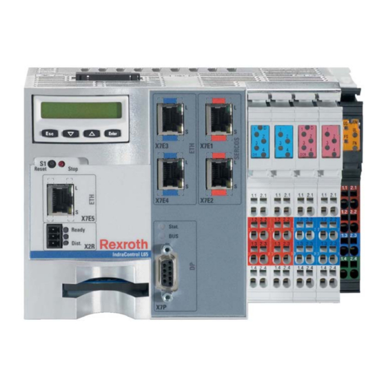
DOK-CONTRL-ICL45L65L85-PR01-EN-P Bosch Rexroth AG 5/81 Rexroth IndraControl L45/L65/L85 Control System Presentation System Presentation Brief DescriptionIndraControl L45/L65/L85 The IndraControl L is a modular and scalable control. The device combines the benefits of an embedded-PC architecture with a standardized I/O system based on terminal technology. -
Page 8: Further Documentation
6/81 Bosch Rexroth AG DOK-CONTRL-ICL45L65L85-PR01-EN-P Rexroth IndraControl L45/L65/L85 Control System Presentation Further Documentation Title Parts number Document in the "Media Directory" on the Bosch Rexroth web site Rexroth IndraMotion MLC Several http://www.boschrexroth.com/various/util‐ functional descriptions ities/mediadirectory/index.jsp?publica‐ tion=NET&objectlang=en- EN&;ccat_id=326148&remindCcat=on Rexroth IndraLogic func‐... -
Page 9: Important Instructions On Use
It must be ensured that the products are installed as specified in the doc‐ umentation. 2.1.2 Areas of Use and Application The Bosch Rexroth IndraControl L45/L65/L85 is suitable for logic and motion applications. The IndraControl L45/L65/L85 may only be used with the accesso‐ ries and mounting parts which are listed in this documentation. -
Page 10: Inappropriate Use
8/81 Bosch Rexroth AG DOK-CONTRL-ICL45L65L85-PR01-EN-P Rexroth IndraControl L45/L65/L85 Control Important Instructions on Use The IndraControl L45/L65/L85 may only be operated under the assembly and installation conditions, in the position of application and under the ambient con‐ ditions (temperature, degree of protection, humidity, EMC, etc.) specified in this documentation. -
Page 11: Safety Instructions For Electric Drives And Controls
DOK-CONTRL-ICL45L65L85-PR01-EN-P Bosch Rexroth AG 9/81 Rexroth IndraControl L45/L65/L85 Control Safety Instructions for Electric Drives and Controls Safety Instructions for Electric Drives and Controls Definition of Terms Component An installation consists of several devices or systems interconnected for a de‐ fined purpose and on a defined site which, however, are not intended to be placed on the market as a single functional unit. -
Page 12: General Information
You must follow these safety instructions. ● Bosch Rexroth is not liable for damages resulting from failure to observe the safety instructions. ●... -
Page 13: Hazards By Improper Use
DOK-CONTRL-ICL45L65L85-PR01-EN-P Bosch Rexroth AG 11/81 Rexroth IndraControl L45/L65/L85 Control Safety Instructions for Electric Drives and Controls concept in which measures of risk reduction for personal safety depend on electrical, electronic or programmable control systems. ● The information given in the application documentation with regard to the use of the delivered components contains only examples of applications and suggestions. -
Page 14: Requirements For Safe Use
12/81 Bosch Rexroth AG DOK-CONTRL-ICL45L65L85-PR01-EN-P Rexroth IndraControl L45/L65/L85 Control Safety Instructions for Electric Drives and Controls ● Risk of injury by improper handling! Injury by crushing, shearing, cutting, hitting! ● Risk of injury by improper handling of batteries! ● Risk of injury by improper handling of pressurized lines! Requirements for Safe Use 3.3.1... -
Page 15: Protective Extra-Low Voltage As Protection Against Electric Shock
Protective extra-low voltage is used to allow connecting devices with basic in‐ sulation to extra-low voltage circuits. On components of an electric drive and control system provided by Bosch Rexroth, all connections and terminals with voltages between 5 and 50 volts are PELV ("Protective Extra-Low Voltage") systems. - Page 16 14/81 Bosch Rexroth AG DOK-CONTRL-ICL45L65L85-PR01-EN-P Rexroth IndraControl L45/L65/L85 Control Safety Instructions for Electric Drives and Controls Dangerous movements! Danger to life, risk of injury, serious injury or property damage! A risk assessment must be prepared for the installation or machine, with its specific conditions, in which the components of the electric drive and control system are installed.
-
Page 17: Protection Against Magnetic And Electromagnetic Fields During Operation And Mounting
DOK-CONTRL-ICL45L65L85-PR01-EN-P Bosch Rexroth AG 15/81 Rexroth IndraControl L45/L65/L85 Control Safety Instructions for Electric Drives and Controls 3.3.4 Protection Against Magnetic and Electromagnetic Fields During Oper‐ ation and Mounting Magnetic and electromagnetic fields generated by current-carrying conductors or permanent magnets of electric motors represent a serious danger to persons with heart pacemakers, metal implants and hearing aids. -
Page 18: Battery Safety
16/81 Bosch Rexroth AG DOK-CONTRL-ICL45L65L85-PR01-EN-P Rexroth IndraControl L45/L65/L85 Control Safety Instructions for Electric Drives and Controls ● Always use suitable tools. Use special tools if specified. ● Use lifting equipment and tools in the correct manner. ● Use suitable protective equipment (hard hat, safety goggles, safety shoes, safety gloves, for example). -
Page 19: Explanation Of Signal Words And The Safety Alert Symbol
DOK-CONTRL-ICL45L65L85-PR01-EN-P Bosch Rexroth AG 17/81 Rexroth IndraControl L45/L65/L85 Control Safety Instructions for Electric Drives and Controls Environmental protection and disposal! The agents (e.g., fluids) used to operate the product might not be environmentally friendly. Dispose of agents harmful to the environment separately from other waste. - Page 20 18/81 Bosch Rexroth AG DOK-CONTRL-ICL45L65L85-PR01-EN-P Rexroth IndraControl L45/L65/L85 Control...
-
Page 21: Technical Data
DOK-CONTRL-ICL45L65L85-PR01-EN-P Bosch Rexroth AG 19/81 Rexroth IndraControl L45/L65/L85 Control Technical Data Technical Data IndraControl L45/L65/L85 Processor CML45.1: AMD LX800 with 500 MHz CML65.1: Intel Celeron M with 1.0 GHz CML85.1: Intel Core2Duo with 1.2 GHz Min. 256 MByte DRAM and min. 256 kByte RDS (see chapter 9 "Ordering Information"... -
Page 22: Ambient Conditions
20/81 Bosch Rexroth AG DOK-CONTRL-ICL45L65L85-PR01-EN-P Rexroth IndraControl L45/L65/L85 Control Technical Data Nominal value DC 24 V Tolerances -15 % / +20 % (without residual ripple) Residual ripple ±5 % 30 V 19.2 V Fig.4-1: Operating voltage according to DIN EN 61131-2... -
Page 23: Used Standards
DOK-CONTRL-ICL45L65L85-PR01-EN-P Bosch Rexroth AG 21/81 Rexroth IndraControl L45/L65/L85 Control Technical Data In operation Storage / Transport Air pressure Up to 2700 m above MSL accord‐ Up to 3000 m above MSL accord‐ ing to DIN 60204 ing to DIN 60204... -
Page 24: Compatibility Test
22/81 Bosch Rexroth AG DOK-CONTRL-ICL45L65L85-PR01-EN-P Rexroth IndraControl L45/L65/L85 Control Technical Data Standard Meaning DIN EN 60 529 Degrees of protection (including housings and installa‐ tion compartments) UL 508 Industrial Control Equipment Fig.4-4: Used standards The IndraControl L45/L65/L85 as well as the additionally available function modules and the Inline terminals correspond to the CE re‐... - Page 25 CMOS battery The service life of a CMOS battery is at least five years. To exchange this bat‐ tery, please contact the Bosch Rexroth Service. The fan has a limited service life. To exchange this fan, please contact the Bosch Rexroth Service.
- Page 26 24/81 Bosch Rexroth AG DOK-CONTRL-ICL45L65L85-PR01-EN-P Rexroth IndraControl L45/L65/L85 Control...
-
Page 27: Dimensions
DOK-CONTRL-ICL45L65L85-PR01-EN-P Bosch Rexroth AG 25/81 Rexroth IndraControl L45/L65/L85 Control Dimensions Dimensions General Information All values in the illustrations are given in mm. Housing Dimensions of the Control The length of the IndraControl L45/L65/L85 housing is 175.9 mm, the width is 120 mm and the height is 107.4 mm. -
Page 28: Housing Dimensions Of The Control With Fan
26/81 Bosch Rexroth AG DOK-CONTRL-ICL45L65L85-PR01-EN-P Rexroth IndraControl L45/L65/L85 Control Dimensions Fig.5-3: Left view (the cut-out for the top-hat rail is arranged centrally) Housing Dimensions of the Control with Fan The fan is available as accessories. For ordering data, please refer chapter 9 "Ordering Information"... -
Page 29: Installation Notes
DOK-CONTRL-ICL45L65L85-PR01-EN-P Bosch Rexroth AG 27/81 Rexroth IndraControl L45/L65/L85 Control Dimensions Fig.5-5: Front view Fig.5-6: Left view (the cut-out for the top-hat rail is arranged centrally) Installation Notes ● Avoid installation locations that are exposed to direct sunlight because this causes additional heat. - Page 30 28/81 Bosch Rexroth AG DOK-CONTRL-ICL45L65L85-PR01-EN-P Rexroth IndraControl L45/L65/L85 Control Dimensions ● Provide the following minimum clearances for sufficient cooling: 100 mm 30 mm 30 mm 100 mm Fig.5-7: Minimum distances for the circulation of surrounding air If there are several rows of function modules, the supply air has to be measured under each row and its limit value must be observed.
-
Page 31: Display And Operating Components
DOK-CONTRL-ICL45L65L85-PR01-EN-P Bosch Rexroth AG 29/81 Rexroth IndraControl L45/L65/L85 Control Display and Operating Components Display and Operating Components General Information On its front, the IndraControl L45/L65/L85 is provided with the following display and operating components: a single-line display with four operating keys as well as a LED and a Reset button. - Page 32 30/81 Bosch Rexroth AG DOK-CONTRL-ICL45L65L85-PR01-EN-P Rexroth IndraControl L45/L65/L85 Control...
-
Page 33: Connections And Interfaces
DOK-CONTRL-ICL45L65L85-PR01-EN-P Bosch Rexroth AG 31/81 Rexroth IndraControl L45/L65/L85 Control Connections and Interfaces Connections and Interfaces Connections on the Front Panel - Overview Designation at Connection type Connector type Mating connector and the housing cable (integrated) (from outside) X7E1 Ethernet RJ45... -
Page 34: Voltage Supply
32/81 Bosch Rexroth AG DOK-CONTRL-ICL45L65L85-PR01-EN-P Rexroth IndraControl L45/L65/L85 Control Connections and Interfaces Fig.7-1: Connections of the IndraControl L45/L65/L85 NOTICE Fitting or removing connectors when voltage is applied, may damage the IndraControl L45/ L65/L85, a function module or an Inline termi‐... - Page 35 DOK-CONTRL-ICL45L65L85-PR01-EN-P Bosch Rexroth AG 33/81 Rexroth IndraControl L45/L65/L85 Control Connections and Interfaces ① Connector for supply voltage of connector set S01 ② Connector for supply voltage of connector set S04 Fig.7-2: Connector for supply voltages Observe the color-coding of the connectors.
-
Page 36: Supply Voltage Uls
34/81 Bosch Rexroth AG DOK-CONTRL-ICL45L65L85-PR01-EN-P Rexroth IndraControl L45/L65/L85 Control Connections and Interfaces Connector contact Signal DC +24 V main voltage (U PGND (ground main and segment voltage) Fig.7-3: Pin assignment on the voltage terminal NOTICE Malfunction if contacts 2.1 and 2.2 are inter‐... -
Page 37: 24 V Supply Voltage Of The Main Circuit U
DOK-CONTRL-ICL45L65L85-PR01-EN-P Bosch Rexroth AG 35/81 Rexroth IndraControl L45/L65/L85 Control Connections and Interfaces 24 V Supply Voltage of the Main Circuit U The 24 V voltage for the main circuit supply U on terminal 2.2 is not used for IndraControl L45/L65/L85. -
Page 38: Uninterruptible Power Supply Ups (Currently Not Supported)
36/81 Bosch Rexroth AG DOK-CONTRL-ICL45L65L85-PR01-EN-P Rexroth IndraControl L45/L65/L85 Control Connections and Interfaces Voltage The voltage in the segment circuit is DC 24 V. Current carrying capacity The maximum current carrying capacity is 8 A (total current with the main cir‐... -
Page 39: Internally Generated Voltages
DOK-CONTRL-ICL45L65L85-PR01-EN-P Bosch Rexroth AG 37/81 Rexroth IndraControl L45/L65/L85 Control Connections and Interfaces Voltage The voltage of the UPS is DC 24 V. Current carrying capacity The performance of the buffer depends on the buffer period. Currently, the voltage supply is not used and does therefore not need to be connected! Controls with a production index <... -
Page 40: Digital Inputs And Outputs
38/81 Bosch Rexroth AG DOK-CONTRL-ICL45L65L85-PR01-EN-P Rexroth IndraControl L45/L65/L85 Control Connections and Interfaces Rexroth Inline IndraControl 24 SEG/F 24 PWR IN PWR IN GNDL PWR IN Voltage terminal at IndraControl L45/L65/L85 R-IL 24 PWR Power terminal R-IL 24 SEG/ Segment terminal with fuse Fig.7-10:... - Page 41 DOK-CONTRL-ICL45L65L85-PR01-EN-P Bosch Rexroth AG 39/81 Rexroth IndraControl L45/L65/L85 Control Connections and Interfaces Slots 1 and 2: Fig.7-12: Digital inputs at connector set S01 Observe the color-coding of the connectors! Number of inputs Connection method 2-wire connection Electrical isolation to U...
-
Page 42: Digital Outputs
40/81 Bosch Rexroth AG DOK-CONTRL-ICL45L65L85-PR01-EN-P Rexroth IndraControl L45/L65/L85 Control Connections and Interfaces Sensor supply From U via a PTC fuse Output voltage Typ. Uext. – 1V Nominal current (total) 0.2 A Short-circuit protection, overcurrent pro‐ Typ. 0.6 A tection Criteria to connect 2-wire proximity... - Page 43 DOK-CONTRL-ICL45L65L85-PR01-EN-P Bosch Rexroth AG 41/81 Rexroth IndraControl L45/L65/L85 Control Connections and Interfaces Slots 4 and 5: Fig.7-16: Digital outputs at connector set S01 Observe the color-coding of the connectors! Number of outputs Connection method 2-wire connection Output type ● Semiconductor outputs, non-saving ●...
- Page 44 42/81 Bosch Rexroth AG DOK-CONTRL-ICL45L65L85-PR01-EN-P Rexroth IndraControl L45/L65/L85 Control Connections and Interfaces Rated output current: - Nominal value 0.5 A - Maximum value acc. to DIN EN 61131-2 <= 0.6 A - Signal 1 2 mA ... 0.6 A - Signal 0 (leakage current) <= 0.5 mA...
-
Page 45: Interfaces
CAT5e with S/STP Transmission rate 10 or 100 MBit/s Ethernet max. 100 m Ethernet RJ45 to the network Fig.7-20: Ethernet interface Bosch Rexroth recommends the use of a STP cable of category 5. This port is intended for the programming device network! -
Page 46: Ethernet Interface (Optional)
Fig.7-21: Ethernet interface Bosch Rexroth recommends the use of a STP cable of category 5. According to the configuration in the application software, these connections can be used for another TCP/IP network or for an RT Ethernet network. -
Page 47: Sercos Iii (Optional)
DOK-CONTRL-ICL45L65L85-PR01-EN-P Bosch Rexroth AG 45/81 Rexroth IndraControl L45/L65/L85 Control Connections and Interfaces Cable type Shielded, twisted pair Transmission rate 9.6 kBit/s to 12 kBit/s RxD/TxD-P CNTR-T DGND VP 100 mA RxD/TxD-N CNTR-N Shield above the metallic plug of the housing Fig.7-22:... -
Page 48: Ready Contact
46/81 Bosch Rexroth AG DOK-CONTRL-ICL45L65L85-PR01-EN-P Rexroth IndraControl L45/L65/L85 Control Connections and Interfaces RJ45, female connector, 8-pin Type: Ethernet 100 Base TX Cable length: 100 m max. Cable type: CAT5e with S/STP Transmission rate: 100 MBit/s Ethernet max. 100 m Ethernet RJ45 to the network Fig.7-26:... -
Page 49: Interface For Compact Flash Card
DOK-CONTRL-ICL45L65L85-PR01-EN-P Bosch Rexroth AG 47/81 Rexroth IndraControl L45/L65/L85 Control Connections and Interfaces UL rating 1 A, DC 60 V (resistive) Dropout time 0.3 ms Bounce time None Watchdog time (analog WD only) 50 ms ± 25 % Fig.7-28: Characteristics of the ready contact If it is in the release status, the ready contact is open. -
Page 50: Function Module Connector
To its left, the IndraControl L45/L65/L85 is provided with a functional module connector that can be used to connect extension modules. This 120-pin connector is a Bosch Rexroth PC104Plus connector where the PC104 signals as well as additional system-specific signals are applied. In other words, only the function modules especially developed for the IndraControl L45/ L65/L85 can be connected to this connector. -
Page 51: Installation And Maintenance
DOK-CONTRL-ICL45L65L85-PR01-EN-P Bosch Rexroth AG 49/81 Rexroth IndraControl L45/L65/L85 Control Installation and Maintenance Installation and Maintenance Mechanical Installation of IndraControl L45/L65/L85 8.1.1 General Information Mount the IndraControl L45/L65/L85 to a mounting rail (standard top-hat rail) according to DIN EN 50022 (3.5 mm x 7.5 mm). -
Page 52: Dismounting The Indracontrol L45/L65/L85
50/81 Bosch Rexroth AG DOK-CONTRL-ICL45L65L85-PR01-EN-P Rexroth IndraControl L45/L65/L85 Control Installation and Maintenance top-hat rail all the way to the left side of the IndraControl L45/L65/L85, until a secure connection via the PCI PLUS bus is established. Mounting the end clamp Finally, attach end clamps to both sides of the Rexroth Inline station. -
Page 53: Mechanical Installation Of Rexroth Inline Terminals
DOK-CONTRL-ICL45L65L85-PR01-EN-P Bosch Rexroth AG 51/81 Rexroth IndraControl L45/L65/L85 Control Installation and Maintenance Mechanical Installation of Rexroth Inline Terminals 8.2.1 General Information Rexroth Inline terminals can be added in series to the right of the IndraCon‐ trol L45/L65/L85 depending on your requirements. No tool is required. On... -
Page 54: Demounting The Inline Terminals
52/81 Bosch Rexroth AG DOK-CONTRL-ICL45L65L85-PR01-EN-P Rexroth IndraControl L45/L65/L85 Control Installation and Maintenance Fig.8-2: Latching a terminal 8.2.3 Demounting the Inline Terminals Proceed as follows to remove a terminal (see fig. 8-3 "Removing a terminal" on page 53): ● Remove the labeling field, if present (see A1 in figure A). -
Page 55: Fuse Replacement
DOK-CONTRL-ICL45L65L85-PR01-EN-P Bosch Rexroth AG 53/81 Rexroth IndraControl L45/L65/L85 Control Installation and Maintenance Fig.8-3: Removing a terminal Changing a terminal If you want to replace a terminal within the Rexroth Inline station, proceed as described above to remove it. Do not latch on the adjacent connector of the neighboring terminal to the left yet. -
Page 56: Electric Installation
54/81 Bosch Rexroth AG DOK-CONTRL-ICL45L65L85-PR01-EN-P Rexroth IndraControl L45/L65/L85 Control Installation and Maintenance Fig.8-4: Fuse replacement Electric Installation 8.3.1 General Information The following rules for setting up a system, in which the electrical equipment like control systems are used, must be adhered to: ●... -
Page 57: External Power Supply Unit
DOK-CONTRL-ICL45L65L85-PR01-EN-P Bosch Rexroth AG 55/81 Rexroth IndraControl L45/L65/L85 Control Installation and Maintenance DANGER Danger of personal injury and material damage due to wrong installation! ● Any dangerous states of the system which might cause personal injury or material damage must be prevented! ●... -
Page 58: Setup With Electrical Isolation
56/81 Bosch Rexroth AG DOK-CONTRL-ICL45L65L85-PR01-EN-P Rexroth IndraControl L45/L65/L85 Control Installation and Maintenance Overvoltage category III 400 V Unit 1 Overvoltage category II 1.2 2.2 24 V 1.3 2.3 E.g. serial terminal UK6-FSI/6 with 1.4 2.4 automatic cut-out TCP10 A by PHOENIX CONTACT... -
Page 59: Reference Conductor Connected To The Protective Conductor
DOK-CONTRL-ICL45L65L85-PR01-EN-P Bosch Rexroth AG 57/81 Rexroth IndraControl L45/L65/L85 Control Installation and Maintenance Overvoltage category III Trans- 400 V former 230 V voltage Power for programming device etc. supply unit 1 Overvoltage category III 400 V 1.1 2.1 Overvoltage category II 24 V 1.2 2.2... -
Page 60: Dimensioning The Voltage Supply
58/81 Bosch Rexroth AG DOK-CONTRL-ICL45L65L85-PR01-EN-P Rexroth IndraControl L45/L65/L85 Control Installation and Maintenance Dimensioning the Voltage Supply When dimensioning the voltage supply, consider the maximum currents (see DIN VDE 0100-523). A voltage of 20.4 … 28.8 V must be applied directly to the unit. -
Page 61: Shield System
DOK-CONTRL-ICL45L65L85-PR01-EN-P Bosch Rexroth AG 59/81 Rexroth IndraControl L45/L65/L85 Control Installation and Maintenance A functional earth ground via the grounding screw is required to ensure opti‐ mum noise immunity. The grounding screw is positioned under the control. The functional earth ground is to be connected via a cable, which is as short as possible or, better, via a ground strip. -
Page 62: Shielding The Profibus Cable
Lay all line and data cables in separate cable channels. Shielding the PROFIBUS Cable To achieve an immune transmission, Bosch Rexroth recommends a two-core twisted and shielded line pair, as is specified as cable type A in EN 50 170, part 8-2. -
Page 63: Connecting Analog Output Terminal R-Ib Il Ao
DOK-CONTRL-ICL45L65L85-PR01-EN-P Bosch Rexroth AG 61/81 Rexroth IndraControl L45/L65/L85 Control Installation and Maintenance Terminal side Sensor side Fig.8-10: Connection of analog sensors in case of signal lines > 10 m If you intend to use both channels of the terminal R-IB IL AI 2/SF, you may connect the shield system in several ways, depending on the line cross-section. -
Page 64: Connecting Lines To Tension Spring Connection Points
62/81 Bosch Rexroth AG DOK-CONTRL-ICL45L65L85-PR01-EN-P Rexroth IndraControl L45/L65/L85 Control Installation and Maintenance Terminal side Actuator side Fig.8-11: Connection of actuators, for signal cables > 10 m 8.3.7 Connecting Lines to Tension Spring Connection Points General Information Connect the lines for peripherals and voltage supply to the tension spring con‐... -
Page 65: Connecting Shielded Cables Using The Shield Connector
DOK-CONTRL-ICL45L65L85-PR01-EN-P Bosch Rexroth AG 63/81 Rexroth IndraControl L45/L65/L85 Control Installation and Maintenance Wire the connectors as required according to the application. Proceed as follows to wire the connectors: ● Strip the line to a length of 8 mm. Wiring is provided without core end sleeves. - Page 66 64/81 Bosch Rexroth AG DOK-CONTRL-ICL45L65L85-PR01-EN-P Rexroth IndraControl L45/L65/L85 Control Installation and Maintenance The desired length (a) depends on the position where you connect the cores and on whether you intend to place the cores between the connec‐ tion point and shield connection in a generous or a tight arrangement.
-
Page 67: Use Of Indracontrol L45/L65/L85 Above 2700 M Above Msl
2700 m above MSL. To use it above 2700 m, the user has to take appropriate measures. This con‐ cerns mainly the track resistance. For use up to 4000 m above MSL Bosch Rexroth recommends the following measures: ●... -
Page 68: Maintenance
LCD Display In case of the deterioration of the readability, the display might have to be re‐ placed. For further information, please contact the Bosch Rexroth Service. CMOS battery The IndraControl L45/L65/L85 devices are provided with a lithium battery to buffer the optional SRAM memory. -
Page 69: Ordering Information
DOK-CONTRL-ICL45L65L85-PR01-EN-P Bosch Rexroth AG 67/81 Rexroth IndraControl L45/L65/L85 Control Ordering Information Ordering Information Type Designation Code 9.1.1 General Information The IndraControl L45/L65/L85 is available in various versions according to the following type codes. 9.1.2 IndraControl L45 Fig.9-1: Type designation code L45... -
Page 70: Indracontrol L65
68/81 Bosch Rexroth AG DOK-CONTRL-ICL45L65L85-PR01-EN-P Rexroth IndraControl L45/L65/L85 Control Ordering Information 9.1.3 IndraControl L65 Fig.9-2: Type designation code L65... -
Page 71: Indracontrol L85
DOK-CONTRL-ICL45L65L85-PR01-EN-P Bosch Rexroth AG 69/81 Rexroth IndraControl L45/L65/L85 Control Ordering Information 9.1.4 IndraControl L85 Fig.9-3: Type designation code L85 Accessories 9.2.1 Required Accessories (Connector Set) General Information To connect the IndraControl L45/L65/L85 an additional connector set is re‐ quired, which includes two input and two output connectors and one power... -
Page 72: Further Accessories (Rexroth Inline Terminals, Function Modules, Interface Cables, Fans)
9.2.2 Further Accessories (Rexroth Inline Terminals, Function Modules, In‐ terface Cables, Fans) Rexroth Inline Terminals The current Rexroth Inline terminals are listed in the Bosch Rexroth product catalog on the Internet http://www.boschrexroth.com/dcc/Vornavigation/Vor‐ Navi.cfm?PageID=g97568&Language=en Rexroth Function Modules Order code... - Page 73 DOK-CONTRL-ICL45L65L85-PR01-EN-P Bosch Rexroth AG 71/81 Rexroth IndraControl L45/L65/L85 Control Ordering Information Order code Parts number Description RKB0007/010,0 R911170149 Ethernet cable, 100Base-TX, CAT.5, cross‐ link, ready-made, with RJ45 connector on both sides, 10.0 m RKB0007/025,0 R911170150 Ethernet cable, 100Base-TX, CAT.5, cross‐...
-
Page 74: Fan
72/81 Bosch Rexroth AG DOK-CONTRL-ICL45L65L85-PR01-EN-P Rexroth IndraControl L45/L65/L85 Control Ordering Information Order code Parts number Description RKB0007/030,0 R911171471 Bus cable, 30.0 m RKB0007/035,0 R911171243 Bus cable, 35.0 m RKB0008/000,5 R911171484 Bus cable, 0.5 m RKB0008/001,0 R911171485 Bus cable, 1.0 m... -
Page 75: Battery
DOK-CONTRL-ICL45L65L85-PR01-EN-P Bosch Rexroth AG 73/81 Rexroth IndraControl L45/L65/L85 Control Ordering Information Battery Order code Parts number Description CAP01.1-B2 R911170806 Button cell for Onboard SRAM; CR2450 Fig.9-12: Battery... - Page 76 74/81 Bosch Rexroth AG DOK-CONTRL-ICL45L65L85-PR01-EN-P Rexroth IndraControl L45/L65/L85 Control...
-
Page 77: Environmental Protection And Disposal
DOK-CONTRL-ICL45L65L85-PR01-EN-P Bosch Rexroth AG 75/81 Rexroth IndraControl L45/L65/L85 Control Environmental Protection and Disposal Environmental Protection and Disposal 10.1 Environmental Protection Production Processes The products are made with energy- and resource-optimized production pro‐ cesses which allow re-using and recycling the resulting waste. We regularly try to replace pollutant-loaded raw materials and supplies by more environment- friendly alternatives. - Page 78 76/81 Bosch Rexroth AG DOK-CONTRL-ICL45L65L85-PR01-EN-P Rexroth IndraControl L45/L65/L85 Control Environmental Protection and Disposal Metals contained in electric and electronic modules can also be recycled by means of special separation processes. Products made of plastics can contain flame retardants. These plastic parts are labeled according to EN ISO 1043.
-
Page 79: Service And Support
DOK-CONTRL-ICL45L65L85-PR01-EN-P Bosch Rexroth AG 77/81 Rexroth IndraControl L45/L65/L85 Control Service and Support Service and Support Our service helpdesk at our headquarters in Lohr, Germany and our worldwide service will assist you with all kinds of enquiries. You can reach us around the clock - even on weekend and on holidays. - Page 80 78/81 Bosch Rexroth AG DOK-CONTRL-ICL45L65L85-PR01-EN-P Rexroth IndraControl L45/L65/L85 Control...
-
Page 81: Index
DOK-CONTRL-ICL45L65L85-PR01-EN-P Bosch Rexroth AG 79/81 Rexroth IndraControl L45/L65/L85 Control Index Index Accessories............69 Ethernet interface..........70 Accumulators............75 Addresses Digital inputs and outputs ......38 Fan..............23, 72 Ambient conditions..........20 Functional earth ground........58 Analog output terminal IB IL AO ......61 Function module connector......... - Page 82 80/81 Bosch Rexroth AG DOK-CONTRL-ICL45L65L85-PR01-EN-P Rexroth IndraControl L45/L65/L85 Control Index Logic circuit............38 Segment circuit........... 36 SERCOS connection.......... 45 SERCOS III Ethernet.......... 71 Shield connector..........63 Main circuit............35 Shielded cables........... 63 Main switches............. 58 Shielding analog sensors and actuators..... 60 Maintenance............
- Page 83 DOK-CONTRL-ICL45L65L85-PR01-EN-P Bosch Rexroth AG 81/81 Rexroth IndraControl L45/L65/L85 Control Notes...
- Page 84 Bosch Rexroth AG Electric Drives and Controls P.O. Box 13 57 97803 Lohr, Germany Bgm.-Dr.-Nebel-Str. 2 97816 Lohr, Germany Tel. +49 (0)93 52-40-0 +49 (0)93 52-48 85 www.boschrexroth.com/electrics Printed in Germany R911332116 DOK-CONTRL-ICL45L65L85-PR01-EN-P...