Table of Contents
Quick Links
Table of Contents

Related Manuals for Bosch D2212B


Summary of Contents for Bosch D2212B
- Page 1 Control/Communicators D2212B/D2212BE Operation and Installation Guide...
- Page 2 D2212B/D2212BE Operation and Installation Guide D2212B/D2212BE Operation and Installation Guide 39934E Page 2 © 2002 Bosch Security Systems...
-
Page 3: Table Of Contents
D132A or D192C ................................14 Enclosure Options ................................14 Installation ......................................15 Mount the Enclosure ................................15 3.1.1 Mounting the D2212B in the D2203 Enclosure ......................15 3.1.2 Mounting the D2212BE in the D2803 Enclosure ..................... 15 Run the Premises Wiring ..............................15 3.2.1 Wire Length .................................. - Page 4 On-Board Points ....................................25 Point 1 (1+ and 1-) ................................25 Points 2 through 6 ................................25 Points 7 and 8 ..................................25 Point Expanders for the D2212B, Wired or RF ......................26 Arming Devices ....................................27 Keyswitch ..................................... 27 7. 1 .1 Description ....................................
- Page 5 Table 2: Referenced Literature ..............................7 Table 3: D2212B/D2212BE Specifications ........................... 11 Table 4: D2212B/D2212BE Compatible Enclosures and Accessories ................12 Table 5: D2212 Terminal Reference ............................31 Table 6: Current Rating Chart for Standby Battery Calculations ..................35 Table 7: System Chart ..................................
- Page 6 D2212B/D2212BE Contents D2212B/D2212BE Operation and Installation Guide 39934E Page 6 © 2002 Bosch Security Systems...
-
Page 7: Introduction
Other Literature Referenced See Table 2 for a listing of related D2212B/D2212BE Control/Communicator documents. They have been included in the table below with their part numbers for easy ordering. Contact Bosch Security Systems if you need to order additional literature. -
Page 8: Documentation Conventions
Important Notes should be heeded for successful operation and programming. Helpful tips and/or shortcuts may be included here. Listings and Approvals The D2212B and D2212BE have the following approvals: Fire • Underwriters Laboratories as a Household Fire and Burglary Warning System Control Unit for NFPA 72 (Chapter 2) Household Fire Warning •... -
Page 9: Fcc Notice
This equipment complies with Part 68 of FCC rules. A label contains, among other information, the FCC registration number and ringer equivalence number (REN). Bosch Security Systems registered the D2212 Control/Communicator for connection to the public telephone network using an RJ31X jack. -
Page 10: Canadian Compliance Notice
Users should not attempt to make such connections themselves, but should contact the appropriate electric inspection authority, or electrician, as appropriate. D2212B/D2212BE Operation and Installation Guide 39934E Page 10 © 2002 Bosch Security Systems... -
Page 11: Overview
5 to 85% @ +86°F (+30°C) non-condensing Humidity Arming Stations D202A Keypad D205 Keypad D206 Keypad D220A Keypad D222 Keypad D223 Keypad D204RF Keypad Keychain Keypad (60-606-319.5) Keyswitch Easikey Table 3: D2212B/D2212BE Specifications D2212B/D2212BE Operation and Installation Guide © 2002 Bosch Security Systems Page 11 39934E... -
Page 12: D2212 Control/Communicator
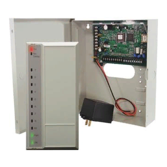
(not for use in UL systems) Easikey Table 4: D2212B/D2212BE Compatible Enclosures and Accessories D2212 Control/Communicator The Bosch Security Systems D2212 Control/Communicator is shipped pre-assembled from the factory. You should receive the following parts with your D2212 panel. 2.2. 1 Panel Assembly •... -
Page 13: Hardware Pack
• Two thread forming screws for mounting the panel to the enclosure 2.2.3 Literature Pack (L2212-LIT) • D2212B/D2212BE Control/Communicator Installation Guide (P/N: 39934) • D2000 Series Control/Communicator Program Entry Guide (P/N: 35114) • Program Record Sheet (P/N: 35113) • Keypad Diagnostics Sheet (P/N: 35110) Ordered Separately 2.3. -
Page 14: D220A Keypad
Enclosure Options The D2212B is shipped in the D2203 enclosure; the D2212BE is shipped in the D2803. If you want to mount the D2212B or D2212BE in one of the optional enclosures listed below, order the D2212BM or D2212BEM, and the enclosure of your choice. -
Page 15: Installation
• Security System User’s Guide for your keypad Mount the Enclosure 3. 1 . 1 Mounting the D2212B in the D2203 Enclosure Snap plastic stand-offs onto these four Open the cover to access the mounting holes in the rear mounting locations. Use screws only at positions 2 and 3. -
Page 16: Emi (Electro Magnetic Interference)
A grounding rod or cold water pipe are recommended earth ground references. Bosch Security Systems does not recommend a telephone or electrical ground for the earth ground connection. Use 18 AWG (1.2 mm) wire maximum under the terminal. Use a spade lug or splice for a larger wire. -
Page 17: Install Detection Devices, Keypads And Bells
Extra power needed for more keypads. Review Power Outputs in Section 4.3, Power Outputs on page 20 to determine the total power output requirements for your system. Instructions for using stand-alone power supplies are included. D2212B/D2212BE Operation and Installation Guide © 2002 Bosch Security Systems... -
Page 18: Auxiliary Power (+Aux)
N/C 1 (Opens from COMM1 when relay is activated.) X1 - (Connect to terminal Ext1 for External Relay 1.) X1 + (Connect to terminal Aux +.) Figure 5: External Relay Wiring D2212B/D2212BE Operation and Installation Guide 39934E Page 18 © 2002 Bosch Security Systems... -
Page 19: Power Module
A 16.5 VAC, 40 VA transformer (Bosch Security Systems D1640) is the primary power source for the D2212B panel. The AC power circuit for the D2212B provides 1.5 A of rectified DC power. The panel reserves 1.0 A of this power for internal operations and 1.0 A for continuously powered devices. -
Page 20: Battery Discharge/Recharge Schedule (No Ac Power)
4.4. 1 On-Board Point 1 Point 1 is a powered sensor loop. Review the Bosch Security Systems D2000 Series Control/Communicator Technogram (P/N: 35112) for a list of compatible detectors. Point 1 is supervised with a 2 kΩ EOL resistor. 4.4.2 Points 2 to 6 Points 2 to 6 are supervised with 1.0 kΩ... -
Page 21: Telephone Connections
Connect the battery and then plug in the transformer. Leave the Standby Switch locked down for now. Program the Panel Use the keypad, Bosch Security Systems D5200 Programmer, or a remote programmer to program the panel. See the D2000 Series Program Entry Guide (P/N: 35114) for programming options and keypad programming instructions. -
Page 22: Unlock The Standby Switch
Dialing Format You can program the panel to use DTMF or pulse dialing. See Phone Parameters in the D2000 Series Program Entry Guide (P/N: 35114). D2212B/D2212BE Operation and Installation Guide 39934E Page 22 © 2002 Bosch Security Systems... -
Page 23: Communication Failure
N/O 1 COMM 1 N/C 1 X1 - (Connect to terminal Ext1 for external relay 1) X1 + D2212 +Aux- Data Figure 11: D133 for Ground Start D2212B/D2212BE Operation and Installation Guide © 2002 Bosch Security Systems Page 23 39934E... - Page 24 D2212B/D2212BE Telephone Connections Notes: D2212B/D2212BE Operation and Installation Guide 39934E Page 24 © 2002 Bosch Security Systems...
-
Page 25: On-Board Points
Use a 2 kΩ EOL resistor for Point 1. See Figure 12 on page 26 for point wiring. Connecting Two-wire Smoke Detectors to Point 1: Connect up to fifteen Bosch Security Systems D262 two-wire smoke detectors to Point 1. Refer to the D2000 Series Control/Communicator Technogram (P/N: 35112), for a complete list of detectors compatible with the D2212. -
Page 26: Point Expanders For The D2212B, Wired Or Rf
Receiver. You can expand the D2212B to 24 points using wired and/or RF point expanders. On-board point numbers are fixed from Point 1 to Point 8. If you use an on-board point, you must use its point number (see the D2000 Series Program Entry Guide [P/N: 35114] for more information). -
Page 27: Arming Devices
To silence the bell (stop Alarm Output) if the system is On (or part On), operate the keyswitch to turn the system Off. If the area is Off, operating the keyswitch only silences the bell. It does not turn the system On. D2212B/D2212BE Operation and Installation Guide © 2002 Bosch Security Systems... -
Page 28: Easikey
Easikey You can use a Bosch Security Systems Easikey Access System to turn the system Off. Program the Keyswitch prompt to Easikey. See the D2000 Series Program Entry Guide (P/N: 35114) for instructions. You must use a 12 VDC option for the Easikey installation. -
Page 29: Appendix A: System Wiring Diagram, Issue A
Reversing Relay Module or a D192C NAC Supervision Module. The alarm output for fire or combined fire/burglary installations must be supervised. Use a D132A and compatible smoke detectors, or a D192C. D2212B/D2212BE Operation and Installation Guide © 2002 Bosch Security Systems... - Page 30 D2212B/D2212BE Appendix A Notes: D2212B/D2212BE Operation and Installation Guide 39934E Page 30 © 2002 Bosch Security Systems...
-
Page 31: Appendix B: Terminal Quick Reference
D2212B/D2212BE Appendix B Appendix B: Terminal Quick Reference Terminal Description D2212B: Connect D1640, 16.5 V, 40 VA Transformer for primary power. 16.5 VAC 16.5 VAC D2212BE: Connect D1625, 16.5 V, 25 VA Transformer for primary power. Earth Ground Connect to earth ground. A cold water pipe or grounding rod is preferred. - Page 32 D2212B/D2212BE Appendix B Notes: D2212B/D2212BE Operation and Installation Guide 39934E Page 32 © 2002 Bosch Security Systems...
-
Page 33: Appendix C: Installation Guide For Ul Applications
Use a D132A and compatible smoke detectors, or a D192C. Two-wire detectors must be electrically compatible, and must be UL Listed for use with the D2212. See the Bosch Security Systems D2000 Series Control/Communicator Technogram (P/N: 35112), or you may contact the detector manufacturer. - Page 34 The D2203 enclosure is suitable for household fire and burglary applications only. Enclosure tamper protection causing an immediate alarm signal is required for all burglary applications. Bosch Security systems offers three optional enclosures: The D8103 enclosure is suitable for residential fire and/or burglary installations and commercial applications. See Table 7 on page 37 for acceptable applications.
-
Page 35: Table 6: Current Rating Chart For Standby Battery Calculations
** If Total C exceeds 860 mA, for fire systems, a stand-alone power supply is required to provide additional current. Table 6: Current Rating Chart for Standby Battery Calculations D2212B/D2212BE Operation and Installation Guide © 2002 Bosch Security Systems Page 35... - Page 36 D2212B/D2212BE Appendix C Notes: D2212B/D2212BE Operation and Installation Guide 39934E Page 36 © 2002 Bosch Security Systems...
-
Page 37: Appendix D: System Chart
Opt. Opt. Opt. Opt. Opt. Enclosure D8122 Derived Optional, contact TelCo for availability of Channel S.T.U. derived channel service D8130 Release Optional Module Table 7: System Chart D2212B/D2212BE Operation and Installation Guide © 2002 Bosch Security Systems Page 37 39934E... - Page 38 D2212B/D2212BE Appendix D Notes: D2212B/D2212BE Operation and Installation Guide 39934E Page 38 © 2002 Bosch Security Systems...
-
Page 39: Index
D206 Keypad ........13 D220A Keypad ........14 D222 Keypad ........14 D223 Keypad ........14 Listings Burglary ..........8 Fire ............8 On-Board Points ........25 D2212B/D2212BE Operation and Installation Guide © 2002 Bosch Security Systems Page 39 39934E... - Page 40 © 2002 Bosch Security Systems 39934E 12/02 130 Perinton Parkway, Fairport NY 14450-9199 Operation and Installation Guide D2212B/D2212BE Customer Service: (800) 538-5807; Technical Support: (888) 886-6189 Page 40 of 40...