
Related Manuals for Bosch FW 200


Summary of Contents for Bosch FW 200
- Page 1 Boiler Energy Management System FW 200 for boilers with Heatronic 3 Installation and Operating Instructions...
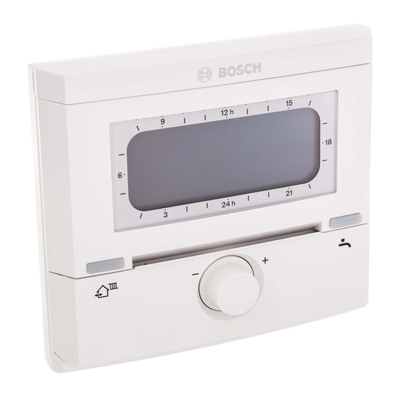
- Page 2 2 | Overview of controls and symbols US/CA Overview of controls and symbols menu info 6 720 643 256-01.1O Fig. 1 Controls 6 720 643 256-05.1O 6 720 643 256-06.1O Fig. 2 Default display for heating circuit 1 Fig. 3 Default display for heating circuit 2 (example for wall mounting) (example for wall mounting)
- Page 3 US/CA Overview of controls and symbols | 3 Controls Symbols 1 Turning dial in + direction (clockwise): Current room temperature (only scrolls menu/information up or increases when mounted on the wall in the setting value living space) Turning dial in – direction (counter- Flashing segment: clockwise): scrolls menu/information down Time now (between 01:45pm and...
-
Page 4: Table Of Contents
4 | Contents US/CA Contents 5.3.3 Changing the domestic hot water Explanation of symbols and safety operating mode (time-limited) . . . 28 information ......7 5.3.4 Vacation mode . -
Page 5: Contents
US/CA Contents | 5 Viewing and entering the customer Menu settings INSTALLER SETTINGS service address ....82 (for installers only) ....57 Viewing system information . - Page 6 6 | Information regarding the documentation US/CA Information regarding the documentation Guide to instructions Deliver all documentation enclosed to the user. If you ..are looking for the safety instructions and • an explanation of the symbols, refer to Section 1.
-
Page 7: Explanation Of Symbols And Safety
US/CA Explanation of symbols and safety information | 7 Explanation of symbols and safety information Additional symbols Explanation of symbols Symbol Meaning Warnings Sequence of steps Warnings are indicated in the text Cross-reference to other points in by a warning triangle and a gray this document or to other background. -
Page 8: Safety Instructions
B Risk of scalding during thermal disinfection: Due to DHW temperatures occurring in excess of 140 °F (60 °C), Bosch strongly advises to install a DHW thermostatic mixing valve. B When there is a risk of frost, leave the boiler switched on and follow the frost protection information. -
Page 9: Information About The Appliance
US/CA Information about the appliance | 9 Information about the appliance The FW 200 can only be connected Scope of delivery to a boiler with BUS-enabled Heatronic 3. These controls are used to display device and • system information and to change the settings shown. -
Page 10: Technical Specifications
10 | Information about the appliance US/CA Technical specifications Cleaning B If necessary, use a damp cloth to wipe the Dimensions Fig. 10, page 15 controls housing. Never use aggressive or Rated voltage 10...24 VDC acidic cleaning agents. Current draw 6 mA (excluding backlight) Controller output... -
Page 11: Supplementary Accessories
US/CA Information about the appliance | 11 Supplementary accessories See also the price list. IPM 2: module for control of up to two mixed • heating zones. Control of one unmixed heating zone in the heating system possible. ISM 2: module for controlling solar water •... -
Page 12: Installation Example
12 | Information about the appliance US/CA Installation example ISM 2 FW 200 Option A System 2 Option E Option C DWUC DWU1 FW 200 FB 100 FB 100 FB 100 IPM 2 IPM 2 Fig. 5 Schematic diagram of system (diagram for installation purposes included in the planning... - Page 13 Option E Thermal disinfection of the solar tank in the boiler or mounted on the wall. If Heating zone pump the FW 200 is installed in the boiler, a 1...4 Solar circuit pump (option A) FB 100 in the first heating zone is Circulation pump for thermal possible.
-
Page 14: Installation (For Installers Only)
14 | Installation (for installers only) US/CA Installation (for installers only) The detailed system diagram for mounting the B Remove cover plate and dummy cover. hydraulic components and the associated control devices can be found in the planning documents or specifications. DANGER: Risk of electric shock! B Prior to mounting this accessory: Isolate the boiler from the power... -
Page 15: Wall Mounting
US/CA Installation (for installers only) | 15 B Click top section into place and mount cover B Select the installation location. plate. 5 9/32" 1 3/8" ≥ 1' (134 mm) (35 mm) (0,3 m) (≥ 0,3 m) 6 720 643 250-02.1O Fig. - Page 16 16 | Installation (for installers only) US/CA B Mount the base. 3 / 6 4 " Ø 2 2 m m ) ( Ø 6 0 9/64" 15/64" 15/64" 9/64" (3,5 mm) (6 mm) (6 mm) (3,5 mm) 6 720 643 250-03.1O Fig.
-
Page 17: Mounting Of The Outdoor Temperature Sensor
US/CA Installation (for installers only) | 17 3.1.3 Mounting of the outdoor temperature sensor Performance depends on installation location of B Select the installation location. outdoor temperature sensor AF. 6 720 643 250-04.1O Fig. 14 6 720 643 256 (2010/05) -
Page 18: Mounting Other Accessories
18 | Installation (for installers only) US/CA B Remove cover. B Attach sensor housing to external wall with two screws. Fig. 15 3.1.4 Mounting other accessories B Mount accessories according to code requirements and the installation instructions supplied. 3.1.5 Disposal B Dispose of packaging in an environmentally responsible manner. -
Page 19: Making The Electrical Connections
3.2.1 Electrical connection in boiler Heatronic 3 B Installation of the controls automatically produces BUS connection via the three contacts ( Fig. 8 on page 14). FW 200 Heatronic 3 ST 19 4 B B 6 720 612 481-05.1R FW 200 Fig. -
Page 20: Commissioning (Installers Only)
20 | Commissioning (installers only) US/CA Commissioning (installers only) For correct commissioning, it is essential that the – If automatic system configuration does following steps are carried out in the order not start of its own accord, start it from shown. -
Page 21: Operation
Introduction The description of a menu options starts with its menu path. That shows you how to reach the With the FW 200 heating controls, you can menu option concerned through the system of automatically control the room temperature and menus. -
Page 22: Heating And Dhw Programs
For each of those operating modes, there is a hot water. That is achieved, for instance, by specified room temperature stored on the deactivating water heating in the periods when FW 200 heating controls ( Section 5.4.1, nobody requires domestic hot water. page 30). -
Page 23: Setting Programs
The user interface of the outdoor reset controls – Select the menu option back FW 200 is implemented as a menu system. Within confirm by pressing the dial that menu system, the various functions are arranged in a hierarchical structure. For greater Press –... -
Page 24: Setting And Changing Switch Points And Operating Modes
24 | Operation US/CA 5.2.2 Setting and changing switch points and B Turn the dial until the menu option operating modes Heating is selected. The way in which switch points and operating modes are set is always the same, the only differences are due to the various operating modes for each switch point. - Page 25 US/CA Operation | 25 B Turn until it points to the required B Press heating program (e.g. A:Program A). The switch point and corresponding segment on the segment ring start to flash. B Press The heating program (e.g. A:Program A) is selected and the title bar shows the current menu name (EDIT PROGRAM A).
- Page 26 26 | Operation US/CA Using groups of days when programming B Press the dial twice. The function Replace with preset program is In many cases, you may want to program the selected and the option No is flashing. same switch points for several days of the week, say for all working days.
-
Page 27: Manual Setting Of Operating Modes
US/CA Operation | 27 If the default display is showing: 5.3.1 Selecting the operating mode for heating B Simultaneously press and hold menu In normal operation, always leave until the following warning message appears: the dial in the position. By using correctly set heating programs, you can save energy and enjoy comfort. -
Page 28: Changing Heating Mode Before The Programmed Time (Bringing Forward The Next Switch Point)
28 | Operation US/CA 5.3.2 Changing heating mode before the 5.3.3 Changing the domestic hot water programmed time (bringing forward the operating mode (time-limited) next switch point) You can use this function if you need This function brings forward the time at which hot water outside the programmed the operating mode Comfort / Economy... - Page 29 US/CA Operation | 29 B Press the dial , the display changes to Programming of the vacation program is now the Vacation menu and Start is selected. complete. If required, you can adjust the heating Now you can enter the date on which you want and domestic hot water modes.
-
Page 30: Changing The Specified Room Temperature
1…2 > Heating levels. B Set values for each operating mode. 1) The bar is shown if the heating controls FW 200 are installed in the boiler facia or room influence is not active. For setting the room influence for installers, see... -
Page 31: Main Menu Settings
US/CA MAIN MENU settings | 31 MAIN MENU settings Moving through menu structure, programming, The menu options are only shown if deleting values and reverting to the default the system components are present setting are described in detail in section 5.2 from and/or active and if no remote page 23. -
Page 32: Main Menu: Vacation
32 | MAIN MENU settings US/CA 6.1.1 MAIN MENU: Vacation Description Menu structure Personal starts Vacation Default setting Control range setting on page Start Today ... 12/31/2099 (31.12.2099) – – . – – . – – – – (in increments of one year/month/ day) Start date ... -
Page 33: Main Menu: Heating
US/CA MAIN MENU settings | 33 6.1.2 MAIN MENU: Heating Description Personal starts Menu structure Heating Default setting Control range setting on page Program – – – Activate – – – Heating circuit 1 A:Program A A:Program A ... (switch points F:Program F from Family (Program name can be changed) - Page 34 34 | MAIN MENU settings US/CA Description Personal starts Menu structure Heating Default setting Control range setting on page Parameter – – – Heating circuit 1 – – – Heating levels – – – Comfort 70 °F (21.0 °C) 32 °F ... 86 °F (0 °C ... 30 °C) °F ( °C) (not lower than Economy) Economy...
-
Page 35: Main Menu: Domestic Hot Water
US/CA MAIN MENU settings | 35 6.1.3 MAIN MENU: Domestic hot water Description Menu structure Personal starts Domestic hot water Default setting Control range setting on page DHW and DHW recirculation Separate Separate programs | As heating pump programs program DHW program –... - Page 36 36 | MAIN MENU settings US/CA Description Menu structure Personal starts Domestic hot water Default setting Control range setting on page Parameter – – – Tank temp in Comfort Mode 140 °F (60 °C) 60 °F (15 °C) ... Maximum tank °F ( °C) temperature Tank temp in Eco Mode...
-
Page 37: Main Menu: General Settings
US/CA MAIN MENU settings | 37 6.1.4 MAIN MENU: General settings Description Menu structure Personal starts on General settings Default setting Control range setting page Time and date – – – Time – – : – – 12:00am ... 11:59 –... -
Page 38: Main Menu: Solar
38 | MAIN MENU settings US/CA 6.1.5 MAIN MENU: Solar Default Personal Description Menu structure Solar setting Control range setting starts on page T2: Max. solar tank temperature 140 °F Disabled (<60 °F or <15 °C) | °F ( °C) (60 °C) 60 °F (15 °C) ...194 °F (90 °C) TB: Max. -
Page 39: Heating Program
For each of those operating modes, there is a Heating circuit 1: Select and activate heating • specified room temperature stored on the program for heating circuit 1. FW 200 heating controls ( Section 6.2.2, Heating circuit 2: Select and activate heating • page 41). - Page 40 40 | MAIN MENU settings US/CA Replace with preset program: Overwrites the For menu structure and adjustment ranges • selected heating program with an existing page 33. heating program of your choice. Menu: Heating > Program > Edit > A:Program A –...
-
Page 41: Temperature Levels For Operating Modes And Heating Rate
US/CA MAIN MENU settings | 41 Menu: Heating > Program > View Menu: Heating > Parameter > Heating circuit > Heating levels B Shows switch points and associated operating modes for All days, Mon - Fri, Sat + Use this menu to set the desired room Sun or the individual day of the week as a temperature for each of the operating modes of segment pattern. -
Page 42: Dhw Program
42 | MAIN MENU settings US/CA With hot water tank: DHW program 1 hour before the first heating circuit switches to Comfort mode, the tank Main menu: Domestic hot water starts heating up to the set hot water temperature (Tank temp in Comfort Set the hot water temperature Mode ). -
Page 43: Dhw Program Operating Modes
US/CA MAIN MENU settings | 43 6.3.1 DHW program operating modes If the DHW program changes from a DHW programs operate differently according to higher to a lower specified the type of domestic hot water system: temperature, the water in the tank With combination boilers (boilers that •... -
Page 44: Timer Program For Domestic Hot Water With Combi Boiler
44 | MAIN MENU settings US/CA 6.3.2 Timer program for domestic hot water For menu structure and adjustment ranges with combi boiler page 35. Menu: Domestic hot water > DHW program Menu: Domestic hot water > DHW program > Edit > Mon - Fri Use this menu if you wish to use a timer program for the domestic hot water. -
Page 45: Time/Temperature Level Program For Domestic Hot Water Via Tank
US/CA MAIN MENU settings | 45 6.3.3 Time/temperature level program for Menu: Domestic hot water > DHW program > domestic hot water via tank Edit > Mon - Fri Use this menu to set identical times for the days Menu: Domestic hot water > DHW program Monday to Friday for the DHW program. -
Page 46: Timer Program For Dhw Recirculation Pump (Systems With Domestic Hot Water Tank Only)
46 | MAIN MENU settings US/CA 6.3.4 Timer program for DHW recirculation P1, P2 ... P6: • pump (systems with domestic hot water For explanation see All days above. tank only) For menu structure and adjustment ranges The recirculation program specifies when a page 35. -
Page 47: Parameters For Domestic Hot Water
US/CA MAIN MENU settings | 47 6.3.5 Parameters for domestic hot water DHW recirc pump cycles:This menu option is • only active if the system has a hot water Menu: Domestic hot water > Parameter recirculation pump. The recirculation pump Tank temp in Comfort Mode: stops during the recirculation pump Off •... -
Page 48: Thermal Disinfection Of Domestic Hot Water
48 | MAIN MENU settings US/CA 6.3.6 Thermal disinfection of domestic hot minutes if the disinfection temperature in water the solar tank has not been reached (Fault Section 9.1 starting on page 86). Menu: Domestic hot water > Thermal Time: Starting time for automatic thermal •... -
Page 49: General Settings
US/CA MAIN MENU settings | 49 Temperature unit: Select unit for the • General settings displayed temperatures, areas, and quantities of energy: 6.4.1 Time, Date °C: temperatures in °C, areas in m – energy quantities in Wh or kWh Menu: General settings > Time and date °F: temperatures in °F, areas in sq.ft., –... -
Page 50: Solar Settings
50 | MAIN MENU settings US/CA TB: Max. temperature tank B: This parameter • Solar settings is only active with a solar recharge system (solar option B). Tank temperature > 140 °F Main menu: Solar (> 60 °C) only if hot water outlet temperature is limited by thermostatic DHW mixer unit. - Page 51 Heating circuit 1 To use as much solar energy as possible, the optimization. FW 200 heating controls can estimate the expected solar yield during the course of the day and take this into account in controlling the DHW optimization and Heating boiler.
-
Page 52: Viewing Information
52 | Viewing information US/CA Viewing information Menu INFO INFO menu overview The table below provides This menu allows you to view a variety of system an overview of the menu structure (column 1). information. • The menu depth is identified by various Detailed instructions on navigating through the shades of gray. - Page 53 US/CA Viewing information | 53 Menu structure INFO Display (example) Description Heating circuit 1 – – Operating mode Auto - Comfort | Auto - Current operating mode for Economy | Auto - Frost | heating circuit 1. Comfort | Economy | Frost | Vacation - Auto | Vacation - Comfort | Vacation - Economy |...
- Page 54 54 | Viewing information US/CA Menu structure INFO Display (example) Description Domestic hot water – – Operating mode DHW single charge | Auto Current operating mode or special mode for ON | Auto OFF | Vacation - domestic hot water with combi boiler. Auto | Vacation ON | Vacation OFF DHW single charge |...
- Page 55 US/CA Viewing information | 55 Menu structure INFO Display (example) Description DWU1: High return valve On | Off Status of the valve DWU1, for return temperature status raising Solar heating support On | Off Shows whether solar energy is currently available for status the heating network.
- Page 56 Does not start until at least 30 days after commissioning. Faults 40 Solar system List of current faults. More detailed information can 03 FW 200 be obtained by selecting with the dial and then EA Boiler pressing the dial to confirm.
-
Page 57: Menu Settings Installer Settings (For Installers Only)
US/CA Menu settings INSTALLER SETTINGS (for installers only) | 57 Menu settings INSTALLER SETTINGS (for installers only) The INSTALLER SETTINGS menu is The menu options are only shown if intended only for installers. the system components are present and/or active and if no remote B To open INSTALLER SETTINGS: control is accessing these. -
Page 58: System Configuration
58 | Menu settings INSTALLER SETTINGS (for installers only) US/CA 8.1.1 INSTALLER SETTINGS: System configuration Description Menu structure Default Personal starts System configuration setting Control range setting on page Start automatic system No | Yes configuration DHW configuration Combi boiler No | Combi boiler | Tank on boiler | Tank on IPM ID. -
Page 59: Heating Parameters
US/CA Menu settings INSTALLER SETTINGS (for installers only) | 59 8.1.2 INSTALLER SETTINGS: Heating parameters Description Menu structure Default Personal starts Heating parameters setting Control range setting on page Heating circuit 1 – – – Heating circuit type Radiators Baseline/Design temp | Radiant Floor | Radiators | Baseboard Base line 78 °F (25 °C) -
Page 60: Solar System Config
60 | Menu settings INSTALLER SETTINGS (for installers only) US/CA Description Menu structure Default Personal starts Heating parameters setting Control range setting on page Minimum outdoor temperature 5 °F ( – 15 °C) – 22 °F ... 32 °F °F ( °C) ( –... -
Page 61: Solar Sys Parameters
US/CA Menu settings INSTALLER SETTINGS (for installers only) | 61 8.1.4 INSTALLER SETTINGS: Solar sys parameters Description Menu structure Default Personal starts Solar sys parameters setting Control range setting on page 1. Standard system – – – SP: ON delta T 14 °F 6 °F ... - Page 62 62 | Menu settings INSTALLER SETTINGS (for installers only) US/CA Description Menu structure Default Personal starts Solar sys parameters setting Control range setting on page B Reload sys – – – PB: ON delta T 10 °F 6 °F ... 36 °F (3 °C ... 20 °C °F ( °C) (6 °C) (not lower than “PB: OFF delta T”...
-
Page 63: Fault History
US/CA Menu settings INSTALLER SETTINGS (for installers only) | 63 Description Menu structure Default Personal starts Solar sys parameters setting Control range setting on page Solar optimization Collector field 1 area 0.0 sq.ft. 0.0 sq.ft ... 1614.6 sq.ft sq.ft. (m (0.0 m (0.0 m ... -
Page 64: System Info
Boiler date of manufacture 06/27/2010 – – (data from boiler) Controller part number and 7 777 777 777 – – model FW 200 (fixed factory setting) Controller date of manufacture 06/27/2010 – – (fixed factory setting) Controller software version JF11.12 (fixed – –... -
Page 65: Installer Settings: Slab Drying
US/CA Menu settings INSTALLER SETTINGS (for installers only) | 65 8.1.8 INSTALLER SETTINGS: Slab drying Description Menu structure Personal starts Slab drying Default setting Control range setting on page Cancel slab drying No/Yes Maximum heating supply 78 °F (25 °C) 78 °F ... -
Page 66: Configuring The Heating System
66 | Menu settings INSTALLER SETTINGS (for installers only) US/CA Heating circuit 2 configuration for • Configuring the heating system configuring the heating circuit 2. Heating circuit 2 remote control for • Installer settings: System configuration deactivating or activating the remote control For menu structure and adjustment ranges on the heating circuit 2. -
Page 67: Parameters For Heating
Use this menu option if you want to correct 8.3.1 Parameters for the entire heating system the displayed room temperature. Installer settings: Heating parameters B Position a precision instrument near FW 200. Minimum outdoor temperature: Set the The precision instrument must not transfer •... -
Page 68: Heating Circuit Parameters
68 | Menu settings INSTALLER SETTINGS (for installers only) US/CA 8.3.2 Heating circuit parameters Menu: Heating parameters > Heating circuit 1 ... Heating circuit 2 Heating circuit type: Use this menu option to • set the heating type for the Heating circuit 1 and/or Heating circuit 2: –... - Page 69 US/CA Menu settings INSTALLER SETTINGS (for installers only) | 69 °F °C °F °C -4 °F -4 °F -20 °C -20 °C 6 720 643 250-09.1O 6 720 643 250-11.1O Fig. 22 Factory setting of heating curve for base Fig. 24 Factory setting for heating curve in point/end point radiator heating system...
- Page 70 70 | Menu settings INSTALLER SETTINGS (for installers only) US/CA Factory setting of parameters for Baseline/Design heating curve temp Radiant Floor Radiators Baseboard Heating surface exponent (fixed – value), curvature of heating curve Minimum outdoor temperature – 6 °F ( – 15 °C) 6 °F ( –...
- Page 71 US/CA Menu settings INSTALLER SETTINGS (for installers only) | 71 Heating OFF until lower level reached: Use Risk of freezing at outdoor temperature: Use • • this menu option to select the cooling down this menu option to set the frost protection phase for the Heating circuit 1 and/or threshold temperature at which the heating Heating circuit 2:...
-
Page 72: Configuring The Solar Thermal System
72 | Menu settings INSTALLER SETTINGS (for installers only) US/CA For menu structure and adjustment ranges Configuring the solar thermal page 60. system The heating system's solar thermal system has to be configured manually. The solar heating system will not be configured as part of the automatic configuration of the heating system ( section 8.2,... -
Page 73: Parameters For Solar Thermal System
US/CA Menu settings INSTALLER SETTINGS (for installers only) | 73 For menu structure and adjustment ranges Parameters for solar thermal page 62. system 8.5.2 Resetting parameters for solar thermal system Fill and bleed the solar thermal system according to its Installer settings: Solar sys parameters documentation and prepare it for This function resets all settings on the Solar sys... -
Page 74: Parameters For Solar Heating Boost
74 | Menu settings INSTALLER SETTINGS (for installers only) US/CA T2: Max. solar tank temperature: For a 8.5.4 Parameters for solar heating boost • detailed description of T2: Max. solar tank system temperature page 50. Menu: Solar sys parameters > 2. Heating Maximum collector temperature: Use this •... -
Page 75: Parameters For The Second Collector
US/CA Menu settings INSTALLER SETTINGS (for installers only) | 75 DWU1: High return valve switch signal: Use 8.5.5 Parameters for the second collector field • this menu option to switch the switch signal Menu: Solar sys parameters > A collector field 2 for the valve to return temperature raising (DWU1): Use this menu if you want to change the... -
Page 76: Parameters For The Solar Recharge
76 | Menu settings INSTALLER SETTINGS (for installers only) US/CA 8.5.6 Parameters for the solar recharge 8.5.7 Parameters for a high/low priority system system Menu: Solar sys parameters > B Reload sys Menu: Solar sys parameters > C High/low priority Use this menu if you want to change the parameters for the solar recharge system. - Page 77 US/CA Menu settings INSTALLER SETTINGS (for installers only) | 77 Charge switchover test duration: Use this DWUC: High/low priority valve mode: Use • • menu option to set the test duration for this menu option to select the operating mode recharge change of priority tank to the storage for the high/low priority valve (DWUC).
-
Page 78: Parameters For An External Heat Exchanger
78 | Menu settings INSTALLER SETTINGS (for installers only) US/CA 8.5.8 Parameters for an external heat exchanger Menu: Solar sys parameters > D Ext heat exchanger Use this menu if you have an external heat exchanger on your solar system. PD: ON delta T: Use this menu option to set •... -
Page 79: Parameters For Thermal
US/CA Menu settings INSTALLER SETTINGS (for installers only) | 79 8.5.9 Parameters for thermal disinfection – Yes: Thermal disinfection active The pump (PE) is activated using the settings on the Menu: Solar sys parameters > E Therm menu Thermal disinfection disinfection section 6.3.6 on page 48) and the Use this menu if you want to thermally disinfect a... -
Page 80: 10Parameters For Solar Optimization
80 | Menu settings INSTALLER SETTINGS (for installers only) US/CA 8.5.10 Parameters for solar optimization – If your location is not shown on the map, leave the number as it is (default setting is Solar optimization is performed automatically 90). according to the available solar output. - Page 81 US/CA Menu settings INSTALLER SETTINGS (for installers only) | 81 6 720 643 250-20.1O Fig. 27 Map of climate zones in North America 6 720 643 256 (2010/05)
-
Page 82: Fault History
82 | Menu settings INSTALLER SETTINGS (for installers only) US/CA Fault history Viewing and entering the customer service address Installer settings: Fault history Installers can use this option to view the last 20 Installer settings: Cust service address faults that have occurred on the system (fault Telephone number: The installer can enter •... -
Page 83: Viewing System Information
US/CA Menu settings INSTALLER SETTINGS (for installers only) | 83 Viewing system information Slab drying function Installer settings: System info Installer settings: Slab drying Shows a variety of system information: The slab drying function allows fresh slab on radiant floor heating to be dried in accordance Installation date (automatically activated on •... - Page 84 84 | Menu settings INSTALLER SETTINGS (for installers only) US/CA Total slab drying time: • – The minimum total duration (3) is °F °C automatically calculated by the heating controls. This is based on a rise of supply temperature of a maximum 18 °F (10 °C) per day.
-
Page 85: Test Of The Actuators On The System
US/CA Menu settings INSTALLER SETTINGS (for installers only) | 85 Mixer, heating circuit 2: See above under • 8.10 Test of the actuators on the Mixer, heating circuit 1 system Tank charge pump: See above under Pump, • heating circuit 1 INSTALLER SETTINGS: Output test DHW recirculation pump: See above under •... -
Page 86: Troubleshooting
86 | Troubleshooting US/CA Troubleshooting BUS device faults are indicated. A boiler fault (e.g. EA fault) is shown in the controls display with the relevant advice. B Notify your installer. For the installer: B Remove the fault in accordance with the details in the boiler documentation. - Page 87 There is a circuit break on the Identify defective controls or Room temp sensor defective room temperature sensor built remote control and replace. into the FW 200/FB 100. There is a short circuit on the room temperature sensor built into the FW 200/FB 100. Fault 10...
- Page 88 88 | Troubleshooting US/CA Display ( Item 1, 3 and 4 in fig. 29) Text Code Cause Remedy (by installer) Fault 11 See display text System configuration: new bus device New ISM detected. Power up all ISMs simultaneously and start automatic system configuration.
- Page 89 Fault 20 Invalid ID in remote control for In combination with FW 200 System configuration: invalid the heating circuit. only ID 1 to 4 is possible in the remote control. Fault 21...
- Page 90 90 | Troubleshooting US/CA Display ( Item 1, 3 and 4 in fig. 29) Text Code Cause Remedy (by installer) Fault 24 See display text in the remote control System configuration: incompatible bus device Fault 28 Remote control installed in Mount remote control in living Remote control is installed in boiler boiler.
- Page 91 US/CA Troubleshooting | 91 Display ( Item 1, 3 and 4 in fig. 29) Text Code Cause Remedy (by installer) Fault 44 Short circuit on the sensor Check temperature sensor (T Temperature sensor T5 at top of solar tank lead (T and replace if necessary.
- Page 92 92 | Troubleshooting US/CA Display ( Item 1, 3 and 4 in fig. 29) Text Code Cause Remedy (by installer) Fault 51 Collector temperature sensor Use correct type of Incorrect temperature sensor type type used as tank temperature temperature sensor. connected sensor (T Technical data in ISM...
- Page 93 US/CA Troubleshooting | 93 Display ( Item 1, 3 and 4 in fig. 29) Text Code Cause Remedy (by installer) Fault 55 Solar system is not yet in Fill, bleed and prepare the Solar system not yet commissioned operation. solar thermal system for commissioning according to its documentation.
-
Page 94: Display
“Heating levels”for “Comfort” or arrange for installer to correct heating curve. Installation site of FW 200 unfavorable, Select a better location for FW 200 and e.g. external wall, close to window, in a ask your installer to reposition it. draft, ... - Page 95 US/CA Troubleshooting | 95 If the fault persists: B Call the authorized installer or customer service and inform them of the fault, quoting the controls details (from the identification plate inside the flap). Appliance details Type:..............Order number:............Date of manufacture (FD...): ........ 6 720 643 256 (2010/05)
-
Page 96: Energy Saving Tips
96 | Energy saving tips US/CA 10 Energy saving tips With outdoor reset controls, the supply above the temperature set for Economy. • temperature is controlled in accordance with Nevertheless energy is being saved as the the set heating curve: The colder the outdoor heating system stays off. -
Page 97: Environmental Protection
US/CA Environmental protection | 97 11 Environmental protection Environmental protection is one of the fundamental company policies of the Bosch Group. We regard quality of performance, economy and environmental protection as equal objectives. Environmental protection laws and regulations are strictly adhered to. -
Page 98: Commissioning Log For The Heating System
98 | Commissioning log for the heating system US/CA 12 Commissioning log for the heating system Home owner/operator: System installer: Date commissioned: FD (Date of manufacture): Number of heating circuits: System for DHW heating: mixed/ unmixed, FB100 : Combi boiler Mixer time _________________sec set. -
Page 99: Individual Timer Program Settings
US/CA Individual timer program settings | 99 13 Individual timer program settings The default settings and personal settings for the timer programs are summarized below. 13.1 Heating program for the heating circuit 1 and heating circuit 2 Setting the heating program is described in section 6.2 on page 39. - Page 100 100 | Individual timer program settings US/CA All day, lunch Monday - 06:00am 08:00am 12:00pm 1:00pm 05:00pm 10:00pm Thursday Friday 06:00am 08:00am 12:00pm 1:00pm 05:00pm 11:30pm Saturday 07:00am 11:30pm – – – – – – – – Sunday 08:00am 10:00pm –...
- Page 101 US/CA Individual timer program settings | 101 Ready-made heating programs in program locations A to F (can be modified) Program A All days Mon - Fri Sat + Sun Monday 06:00am 10:00pm Tuesday 06:00am 10:00pm Wednesday 06:00am 10:00pm Thursday 06:00am 10:00pm Friday 06:00am...
- Page 102 102 | Individual timer program settings US/CA Program D All days Mon - Fri Sat + Sun Monday 06:00am 10:00pm Tuesday 06:00am 10:00pm Wednesday 06:00am 10:00pm Thursday 06:00am 10:00pm Friday 06:00am 11:30pm Saturday 07:00am 11:30pm Sunday 08:00am 10:00pm Program E All days Mon - Fri Sat + Sun...
- Page 103 US/CA Individual timer program settings | 103 Own settings Program position A, Name: ________________________, assigned to heating circuit: ____ All days Mon - Fri Sat + Sun Monday Tuesday Wednesday Thursday Friday Saturday Sunday Program position B, Name: ________________________, assigned to heating circuit: ____ All days Mon - Fri Sat + Sun...
- Page 104 104 | Individual timer program settings US/CA Program position D, Name: ________________________, assigned to heating circuit: ____ All days Mon - Fri Sat + Sun Monday Tuesday Wednesday Thursday Friday Saturday Sunday Program position E, Name: ________________________, assigned to heating circuit: ____ All days Mon - Fri Sat + Sun...
-
Page 105: Dhw Program
US/CA Individual timer program settings | 105 13.2 DHW program How to set the DHW program is described in Section 6.3 on page 42. °F/ °F/ °F/ °F/ °F/ °F/ °C °C °C °C °C °C Factory settings Monday - 140 °F 59 °F 05:00am... -
Page 106: Dhw Circulation Program
106 | Individual timer program settings US/CA 13.3 DHW circulation program How to set the hot water circulation program is described in Section 6.3 on page 42. Factory settings Monday - 06:00am 11:00pm – – – – – – – –... -
Page 107: Index
US/CA Index | 107 Index Accessories ..........11, 18 Default settings ........26, 58, 73 Adjust internal room sensor ......67 Design temperature ........70 Automatic system configuration ....20, 66 Details about the device - Scope of delivery ......... 9 - Technical specifications ......10 DHW recirculation pump CP ...... - Page 108 Mounting - Output test ..........65 - Accessories ..........18 - Slab drying ...........65, 83 - FW 200 in boiler ........14 - Solar system parameters ......61, 73 - FW 200 to wall ........... 15 - System configuration ......58, 66 - Outdoor temperature sensor ..... 17 - System faults ..........82...
- Page 109 US/CA Index | 109 Old appliances ..........97 Radiant floor heating ....68–69, 83, 96 Operation ............21 Radiators ..........68–69 - Changing hot water mode ......28 Recharge system ..........76 - Changing room temperature ....30, 41 Recycling ............97 - Changing the operating mode for heating ..28 Reset - Setting heating temperature ......41 - All settings ..........
- Page 110 110 | Index US/CA Solar optimization ...........51 Solar program ...........38, 50 Technical specifications ......... 10 Solar pump Test - PC ...............77 - Actuators ........... 85 - SP ............73–75 - Outputs for pumps and mixer ....85 Solar radiation ..........94 Thermal disinfection ......29, 48, 79 Solar standard system ........72 Thermostatic valves ........
- Page 111 US/CA Index | 111 Notes 6 720 643 256 (2010/05)
- Page 112 50 Wentworth Avenue Londonderry, NH 03053 Tel. 603-552-1100 Fax 603-584-1681 www.bosch.us U.S.A. Products manufactured by Bosch Thermotechnik GmbH Junkersstrasse 20-24 D-73249 Wernau www.bosch-thermotechnology.com Bosch Thermotechnology Corp. reserves the right to make changes without notice due to continuing engineering and technological advances. 067206432561...