
Related Manuals for Bosch RC35


Summary of Contents for Bosch RC35
- Page 1 Installation and Room controller service instructions Logamatic EMS Programming unit RC35...
-
Page 2: Table Of Contents
Replacement of ERC with RC35 ........ - Page 3 RC35 calibration ........
-
Page 4: Guide To Instructions
Guide to instructions These installation and maintenance instructions contain all the information about the functions and settings of the Logamatic RC35 programming unit. Introduction to the service menu Chapter 4.2 explains in detail the steps needed for programming all the settings in the service menu. -
Page 5: Key To Symbols And Safety Instructions
Key to symbols and safety instructions Key to symbols and safety instructions 1.1 Explanation of symbols Warnings Warnings in this document are framed and identified by a warning triangle printed against a grey background. If there is a risk of electric shock, the exclamation mark in the warning triangle is replaced by a lightning symbol. -
Page 6: Safety Instructions
Key to symbols and safety instructions 1.2 Safety instructions Installation and commissioning B Observe these instructions to ensure satisfactory operation. B The appliance must only be installed and commissioned by an authorised installer. Risk of death from electric shock B The power supply must be connected by a qualified electrician. B Observe the connection diagram. -
Page 7: Product Information
50). RC35 as replacement for ERC If the RC35 programming unit is used as a replacement for the ERC controller, there are differences for example as regards the basic settings. For an overview of these, see Tab. 4, page 10. -
Page 8: Specification
0 to +70 Relative humidity 0 to 90 CE designation Table 2 Specification - programming unit RC35 Temperature sensor characteristics When measuring temperature sensors, observe the following requirements: • Isolate the system before measuring. • Measure the resistance at the cable ends. -
Page 9: Validity Of These Instructions For Function Modules (Accessories)
For detailed information regarding suitable accessories, see the catalogue. • Mixer module MM10 for triggering a 3 way valve is not possible. A description of the MM10 is included in the RC35 instructions. • Switching moduleWM10 for operation of a hydraulic low loss header •... -
Page 10: Replacement Of Erc With Rc35
Product information 2.7 Replacement of ERC with RC35 Topic RC35 Note See page Setback modes Changeover Selection of four Deviation, e.g. 37 – 38 (night setback) between setback modes: modified outside “Shutdown” and temperature • Reduced “Outdoor setback threshold for outside operationShut- mode”... -
Page 11: Installation
Installation Installation 3.1 Choosing the right installation position 3.1.1 Installation in the reference room If the system is operated in room temperature-dependent mode, observe the following requirements: • Installation position on an internal wall ( fig. 1) • Maintain the specified distance from the door (to avoid draughts). •... -
Page 12: Installation On Boiler
Installation 3.1.2 Installation on boiler If a HM10 hybrid module is used, the installation must be carried out with the wall bracket. If it is installed on the boiler, it does not function correctly. Installation directly on the boiler is possible where the boiler is equipped with the Energy Management System (EMS). -
Page 13: Installation And Connections
Installation 6 720 641 642-01.1RS Fig. 2 Options for a heating system with two heating circuits Both heating circuits are controlled by one programming unit. Each heating circuit has its own programming unit / remote control unit. 3.3 Installation and connections Only use the wall mounting base with screw terminals. - Page 14 “RC” connection to the EMS (boiler) “EXT” terminals for external room temperature sensor or for jumper B If the RC35 programming unit is operated without external room temperature sensor, a jumper is required at the “EXT” cable terminals [6] (condition as supplied from the factory).
-
Page 15: Hooking In Or Removing The Programming Unit
Installation 3.4 Hooking in or removing the programming unit Hooking in the programming unit 1. Hook the programming unit at the top into the mounting plate in the direction of the arrows. 2. Push the programming unit at the bottom in the direction of the arrow against the mounting plate until it clicks into place. -
Page 16: Principles Of Operation
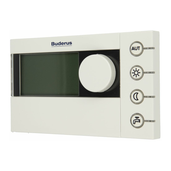
Principles of operation Principles of operation 4.1 Overview of controls Key to diagram: Flap; pull the recessed grip on the left to open Display Rotary selector for changing values and temperatures or for moving within the menus Keys for basic functions: When the LED lights up, “AUT”... -
Page 17: Introduction To The Service Menu
Principles of operation 4.2 Introduction to the service menu You can use the SERVICE MENU to set the parameters for the system. It also contains functions for diagnosis, maintenance purposes, and carrying out a reset. The procedure for operation is always the same: 1. - Page 18 Principles of operation Operation Result Press to select boiler data. SETTINGS\BOILER The menu SETTINGS\BOILER is opened. What type of building do you have? medium To change the value, hold down the button (the value SETTINGS\BOILER starts flashing) and turn the rotary selector at the same What type of building time.
-
Page 19: Overview Of The Service Menu
Domestic hot Parameters for DHW water Solar data If solar is installed: see documentation for the solar module RC35 calibration Parameters: calibration of the displayed room temperature Contact details Entering the heating contractor's name and telephone number 1)2) Diagnosis... -
Page 20: Commissioning
Result Switch on the heating system. RC35 version: connect to: While setting up the connection between the RC35 and EMS connection setup ... or UBA1.x, the display shows the message on the right. please wait If the display shows a different message, look it up in Chapter 10, page 53. -
Page 21: Checklist: Important Parameters For Commissioning
Commissioning 5.2 Checklist: important parameters for commissioning When commissioning the device, ensure the satisfaction of both parties, making sure that the heating system meets the customer's needs and will not give cause for complaints. In our experience, the following parameters are very important for the satisfaction of the system user: B Find out the system owner's requirements and preferences regarding: SERVICE Standard... -
Page 22: Quick Start-Up (Quick Programmer Menu)
HEATING CIRCUIT Which operating unit RC2x/ RC35 Assigning programming is assigned to heating RC20/RF, units to heating circuits circuit 1? RC35, none page 35). General (and other heating heating circuit data ( How should heating Outside Outside circuits) page 31). - Page 23 Commissioning Standard SHORTPROG\ Menu item Input range setting Other information Have you installed Yes, No domestic hot water? What should be used 3-way Three-way for domestic hot diverter valve diverter water heating? cylinder valve primary pump To which temperature 30 °C to 60 °C In order to be able to should your domestic...
-
Page 24: Detailed Commissioning
5.6 Shutting down/switching off The RC35 programming unit is powered via the heating system and remains permanently on. The heating system is only switched off for maintenance work, for example. B For switching the heating system on or off: switch the On/Off switch on the boiler programming unit to position 1 (ON) or 0 (OFF). -
Page 25: Operating Information
In a BUS system, only one subscriber can carry out the calculations for a heating circuit. Consequently, only one RC35 programming unit may be installed in each heating system. If additional programming units (e.g. RC2x) are required, they must be installed as remote... -
Page 26: System Settings (Service Menu - Settings)
System settings (Service menu – Settings) System settings (Service menu – Settings) B Press simultaneously, to open the SERVICE MENU. B Turn the rotary selector to the left until settings is selected. B Press to open menu SERVICE\SETTINGS. SERVICE MENU quick operation settings diagnosis... -
Page 27: Building Type (Adjusting The Outside Temperature)
System settings (Service menu – Settings) Input Standard Menu item range setting Other information Should the adjusting of the Yes, No When selecting “yes” the following outside temperature be switched parameter building type will be off? hidden. What type of building do you Light, Medium Building type (heat storage capacity),... -
Page 28: Minimum Outside Temperature
System settings (Service menu – Settings) Example: 6 720 618 477-05.1RS Fig. 6 This greatly simplified example shows how the adjusted outside temperature follows the outside temperature, but does not reach its extreme values. Current outside temperature Adjusted outside temperature In the basic setting any changes in the outside temperature have an effect after a delay of three hours at the latest (30 x 6 minutes = 180 minutes) on the calculation of the outside temperature compensated control. -
Page 29: Hybrid
System settings (Service menu – Settings) 6.2 Hybrid B Turn the rotary selector to the left until Hybrid is selected. B Press to select Hybrid. SERVICE\SETTINGS The SETTINGS\HYBRID menu is opened plant data hybrid boiler data heating circuit 1 Other Menu item Input range Standard setting... -
Page 30: Boiler Data
System settings (Service menu – Settings) 6.3 Boiler data B Turn the rotary selector to the left until boiler data is selected. B Press to select boiler data. SERVICE\SETTINGS The menu SETTINGS\BOILER is opened. plant data boiler data domestic hot water heating circuit 1 Standard Menu item... -
Page 31: Heating Circuit Data
How should heating Outside Outside “Room temperature compensated” circuit 1 be controlled? temperature temperature can only be set if RC2x or RC35 has compensated, compen- been allocated. If “room temperature room temperature sated compensated” is selected, room compensated flow is used. - Page 32 37) mode, mode reduced mode, room compensation mode (only if RC35 or RC2x have been allocated to the heating circuit), switch-off mode Table 14 Navigator for service menu of SETTING\HEATING CIRCUIT 1 Logamatic EMS – 6 720 801 387 (2011/05)
- Page 33 What temp. should be Outside Outside Room temperature adjustment only used to trigger frost temperature, room temperatur if RC2x or RC35 have been protection? temperature, no assigned to the heating circuit frost protection page 38). Which frost protection -20 °C to +10 °C 5 °C...
- Page 34 System settings (Service menu – Settings) Standard Menu item Input range setting Other information What is the desired 25 °C to 60 °C 45 °C maximum flow temperature? For how many days 0 days to 20 days 4 days should maximum flow temp.
-
Page 35: Assignment Of Programming Unit / Remote Control Unit In The Software
Setting: Which operating unit is assigned to the heating circuit? Effect HK 1 = RC35, HK 2 = RC35 same room temperatures for HK 1 and HK 2 fig. 2, [1],Seite 13) HK 1 = none, HK 2 = RC35 Room temperatures for HK 1 and HK 2 can be fig. -
Page 36: Heating Curve
System settings (Service menu – Settings) 6.4.3 Heating curve Parameter: design temperature, maximum and minimum flow temperature and room temperature offset (parallel shift). The heating curve is the decisive basic factor for an economic and convenient operation of the heating system with outside temperature compensated control. For the calculation of this curve the Logamatic control system requires information about some of the heating system characteristics, and from this it calculates automatically and by means of a mathematical formula the optimum heating curve. -
Page 37: Reduction Modes (Night Reduction)
System settings (Service menu – Settings) T minA T minA 6 720 618 477-06.1RS Fig. 7 Setting of the heating curve. Left: setting the gradient by means of design temperature and minimum outside temperature. Right: parallel offset possible by means of offset or set room temperature. -
Page 38: Frost Prot
• Room temperature(Room temperature sensor of the RC35 or RC2x). If the room temperature falls below the fixed set value of 5 °C, the heating circuit pump is automatically switched on. The heating circuit pump stops automatically if the room temperature rises above 7 °C. - Page 39 System settings (Service menu – Settings) From which outside temperature should the reduction be interrupted? DIN-EN 12831 requires that, for the maintaining of a comfortable heat, all heating surfaces and heat generators are designed to a defined output, if the heating system cools down below a defined value due to night reduction.
-
Page 40: Dhw
System settings (Service menu – Settings) 6.5 DHW WARNING: Scalding hazard at the DHW taps. If DHW temperatures over 60 °C are settable and present during thermal disinfection, there is a scalding hazard at the DHW taps. B Inform the customer that he should only turn on mixed water. B Turn the rotary selector to the left until DHW is selected. - Page 41 System settings (Service menu – Settings) Standard Menu item Input range setting Other information 2)3) Circulation Is a circulation pump Yes, No installed? How frequently should the once for 3 twice for 3 circul. pump be switched on minutes, twice for minutes per hour? 3 minutes, 3 times...
- Page 42 System settings (Service menu – Settings) Standard Menu item Input range setting Other information Should the LED of the single Yes, No The single loading function charge key be activated? remains, but it is not displayed via LED. Start delay in case of preheated Off, This function depends on the DHW (e.g.
-
Page 43: Solar Data
System settings (Service menu – Settings) 6.6 Solar data B Turn the rotary selector to the left until solar data is selected. B Press to select solar data. SERVICE\SETTINGS Menu SETTINGS\SOLAR opens. boiler data domestic hot water heating circuit 1 solar data Other Menu item... -
Page 44: Rc35 Calibration
System settings (Service menu – Settings) 6.7 RC35 calibration B Turn the rotary selector to the left until RC35 calibration is selected B Press button to select RC35 calibration. SERVICE\SETTINGS The menu for SETTING/RC35 CAL is opened. domestic hot water... -
Page 45: Contact Details
B Press to select contact data. SERVICE\SETTINGS Menu SETTING\CONTACT opens. heating circuit 1 solar data RC35 calibration contact data Menu item Input range Other information Name and tel. No. of _ _ _ _ _ _ _ _ _ _ _... -
Page 46: Diagnosis
Diagnosis Diagnosis The diagnosis service menu contains a number of tools for diagnosis: 1), 2) • Function test: • Monitor value • Fault display: • Heating curve • Versions B Press simultaneously, to open the SERVICE MENU. B Turn the rotary selector to the left until diagnosis is selected. -
Page 47: Function Test
Diagnosis 7.1 Function test With this menu you can trigger specific individual EMS components, in order to test their function. 1), 2), 3) The available functions and the possible settings vary depending on the system installed. B Hold the button pressed down and simultaneously turn the rotary FCT. -
Page 48: Monitor Value
Diagnosis 7.2 Monitor value You can use the monitor value menu to view the set and actual values for the heating system. The set value will be displayed first and then the actual value. The values displayed for monitoring purposes vary depending on the system installed. If the values to be displayed do not all fit on the screen, they are displayed as a list. -
Page 49: Error Message
: with blocking faults the heating system continues to work automatically as soon as the error status is lifted. • System errors in the heating system are recorded in the RC35 programming unit, with the exception of faults in the boiler or burner, which are either “locking” or “blocking” faults. The heating system keeps operating as much as possible during the fault;... -
Page 50: Heating Curve
You can use the INFO\VERSIONS menu to view the software versions for heating system components. B If the information can not be depicted in one display, turn the rotary INFO\VERSIONS selector to show the next display. RC35 1.02 UBA1.5 1.21 Logamatic EMS – 6 720 801 387 (2011/05) -
Page 51: Service
The interval can expire after a certain number of hours run or when a specific date is reached. The RC35 programming unit will then show a service message so that the customer can notify you to arrange an appointment. -
Page 52: Reset
B Once reset is complete: confirm the new message by pressing any key. 1) With boilers with UBA1.x, DBA or UBA-H3 only all the parameters of the RC35 are reset, but not the parameters of the automatic firing units of. -
Page 53: Troubleshooting
Troubleshooting 10 Troubleshooting This fault table lists possible system faults, i.e. faults in EMS components. The heating system keeps operating as long as possible in the event of a system fault; in other words, heating can continue. Only use original Buderus spare parts. Losses caused by the use of parts not supplied by Buderus are excluded from the Buderus warranty. - Page 54 Troubleshooting Effect on control SC FC Error display characteristics Possible cause Remedy B Stop any leaks. A01 810 DHW stays It is always the aim to Constant drawing or cold heat up the DHW system leak. cylinder to the set DHW B Check sensor Temperature sensor target value.
- Page 55 B RC35Replace . A11 801 Internal Heating system is in Internal runtime error error emergency mode. in the RC35. B Enter the current A11 802 Time is not Restricted functionality Time details are yet set. for: missing, e.g. due to time.
- Page 56 With room temperature compensated control it is controlled to maximum HKx temperature. B Check the A11 816 No RC20/RF unable to RC20/RF has communicati transmit data to RC35. incorrect address. address on with Therefore no room (parameter P1) in RC35. temperature RC20/RF.
- Page 57 SC FC Error display characteristics Possible cause Remedy B Change parameter A18 825 Two master RC35 and RC2x regulate RC2x and RC35 are programmin both heating circuits and both logged on as P1 in RC2x or g units in the DHW.
- Page 58 SC FC Error display characteristics Possible cause Remedy B Set A2x 829 RC20/RF as RC20/RF unable to RC20/RF address remote transmit data to RC35. incorrectly allocated programming control. Therefore no room in RC35 or not unit parameters in temperature installed in RC35.
- Page 59 Heating circuit x cannot Heating circuit communicati be operated addresses on MM10 coding switch on on with HCx correctly.MM10 and and RC35 do not MM10. mixer actuator (mixer) are match. module. running independently in B Check terminals MM10 or BUS cable...
-
Page 60: Service Menu Rc35
Service menu RC35 11 Service menu RC35 Logamatic EMS – 6 720 801 387 (2011/05) -
Page 61: Index
Index Index Accessories ......9 Flow temperature ..... . 36 Adjusting of the outside temperature . - Page 62 Index Power failure ......24 Temperature sensor ..... 8 Programming unit Testing of components .
- Page 63 Notes Logamatic EMS – 6 720 801 387 (2011/05)
- Page 64 Buderus Cotswold Way, Warndon, Worcester WR4 9SW All Enquiries: 0844 892 3004 www.buderus.co.uk In the UK and IE, Buderus is a brand name of Bosch Thermotechnology Ltd.