Table of Contents
Table of Contents

Related Manuals for Bosch rexroth ctrlX CORE


Summary of Contents for Bosch rexroth ctrlX CORE
- Page 1 Operating Manual ctrlX CORE Controls R911405645, Edition 05...
- Page 2 Copyright © Bosch Rexroth AG 2022 All rights reserved, also regarding any disposal, exploitation, reproduction, editing, distribution, as well as in the event of applications for industrial property rights. Liability The specified data is intended for product description purposes only and shall not be deemed to be a guaranteed characteristic unless expressly stipulated in the contract.
-
Page 3: Table Of Contents
UK declaration of conformity........R911405645, Edition 05 Bosch Rexroth AG... - Page 4 12.6 Real-time clock ..........40 Bosch Rexroth AG...
- Page 5 16.2 Packaging............44 17 Service and support Index R911405645, Edition 05 Bosch Rexroth AG...
-
Page 6: About This Documentation
Fig. 1: Assigning the present documentation to the target groups, product phases and activities of the target group This document instructs the technical staff of the machine manufacturer on how to safely perform the mechanical and electrical installation and on how to commission the device. Bosch Rexroth AG R911405645, Edition 05... -
Page 7: Scope
Customer requests, comments or suggestions for improvement are of great importance. Please email your feedback on the documentations to [email protected]. Directly insert ⮫ comments into the electronic PDF document and send the PDF file to Bosch Rexroth. R911405645, Edition 05 Bosch Rexroth AG... -
Page 8: Product Identification And Scope Of Delivery
12 State of revision 26 CCC marking 13 Serial number 27 Name of origin 14 Rated voltage Scope of delivery • ctrlX CORE control • 24 V power connector, 2-pin (ctrlX CORE X2 and ctrlX CORE X3) Bosch Rexroth AG R911405645, Edition 05... -
Page 9: Using Safety Instructions
In case of non-compliance with this safety instruction, minor or moderate CAUTION injury can occur. In case of non-compliance with this safety instruction, material damage can NOTICE occur. Symbols used This is a tip. R911405645, Edition 05 Bosch Rexroth AG... -
Page 10: Explaining The Signal Alert Symbol On The Device
General mechanical engineering • Building automation Danger due to unintended use WARNING The protection specified by Bosch Rexroth cannot be ensured if not used as intended. − Use the product exclusively as intended by Bosch Rexroth. − Operate this device only under the mounting and installation conditions, in the position and under the ambient conditions (temperature, degree of protection, humidity, EMC etc.) specified in this documentation. -
Page 11: Sd Card
The frequency of the refresh cycle depends on the service life of the memory. If a refresh cycle is not possible anymore, data can be lost. Notes on the temperature display: • "Temperature (CPU)" shows the internal CPU temperature. • "Temperature" shows the temperature on the PCB. R911405645, Edition 05 Bosch Rexroth AG... -
Page 12: Ambient Conditions
Defective product due to gases jeopardizing functions NOTICE Due to the risk of corrosion, avoid sulphurous gases (e.g. sulphur dioxide ) and hydrogen sulphide (H S)). The product is not resistant against these gases. Bosch Rexroth AG R911405645, Edition 05... -
Page 13: Technical Data
314 g 346 g Dimensions Refer to ⮫ Chapter 10.1 Refer to ⮫ Chapter 10.1 Refer to ⮫ Chapter 10.1 “Housing dimensions” “Housing dimensions” “Housing dimensions” on page 23 on page 23 on page 23 R911405645, Edition 05 Bosch Rexroth AG... -
Page 14: Voltage Supply And Current Consumption
Overvoltage protection U and U Present, fuses can trigger in case of overvoltage. Transient protection U and U Present, suppressor diodes Pulse load up to 1,500 W Bosch Rexroth AG R911405645, Edition 05... -
Page 15: Standards
Equipement électrique des machines DIN EN 61131-2 Speicherprogrammierbare Steuerungen 2008 Teil 2: Betriebsmittelanforderungen und Prüfungen – Programmable controllers Part 2: Equipment requirements and tests – Automates programmables Partie 2: Spécifications et essais des équipements R911405645, Edition 05 Bosch Rexroth AG... -
Page 16: Ce Marking
(EMC) – Normes sur la compatibilité électromagnétique (CEM) Norm Bedeutung Ausgabe Standard Meaning Edition Norme Signification Édition DIN EN 61000-6-2 Elektromagnetische Verträglichkeit (EMV) November 2019 Teil: 6-2: Fachgrundnormen – Störfestigkeit für Industrieber- eiche Normes génériques – Immunité pour les environnements industriels Bosch Rexroth AG R911405645, Edition 05... -
Page 17: Ul/Csa Certified
Loss of CE conformity due to modifications at the device. CE marking applies only to the device upon delivery. After modifying the device, verify the CE conformity. For the CE declaration of conformity, go to the Bosch Rexroth media directory: ⮫ www.bos- chrexroth.com/MediaDirectory, search term "DCTC-30455-001". -
Page 18: Interfaces
RJ45 socket RJ45 plug 10/100/1000 MBit 8-pin (twisted pair, 8-wire) HMI and engineering port ➂ ✓ ✓ ✓ XF50 Ethernet RJ45 socket RJ45 plug 10/100/1000 MBit 8-pin (twisted pair, 8-wire) Field bus master (Ethercat) Bosch Rexroth AG R911405645, Edition 05... -
Page 19: Local Bus Interface Ethercat Of Ctrlx Core
, only the current consumption of the infeed terminal and the I/O modules. For the integration into the parent system, the respective ESI files are available. For the ESI files, go to ⮫ http://www.bos- chrexroth.com/electrics. Synchronizing the application The application is synchronized in the "SM synchronous" mode. R911405645, Edition 05 Bosch Rexroth AG... - Page 20 Error settings 10F3 Diagnosis history 10F8 Timestamp object 1Ann PDO Mapping TxPDO 1C00 Sync manager type 1C12 Sync manager 2 assignment 1C13 Sync manager 3 assignment 1C33 SM input parameter F000 Modular device profile Bosch Rexroth AG R911405645, Edition 05...
- Page 21 0x3411 6020:06 Overcurrent 0x2315 8000 System info 8000:01 Temperature Int16 0x4210 1/100 °C 0x4220 8000:02 Power logic used Uint16 8000:03 Power logic avail- Uint16 able A000:0 Material number String(20) A010:0 Full serial number String(20) R911405645, Edition 05 Bosch Rexroth AG...
- Page 22 10F1 Error settings Diagnosis history object 20 diagnostic messages can be stored 10F3 Diagnosis history For the status codes of the "Ethercat state machine" and the diagnostic codes across all modules, refer to . Bosch Rexroth AG R911405645, Edition 05...
-
Page 23: Mounting, Dismounting And Electric Installation
Setting of the object response. Refer to ETG.1020 In case of overvoltage or undervoltage of U , all modules connected to the segment circuit are switched off. Mounting, dismounting and electric installation 10.1 Housing dimensions 97.5 Fig. 5: Front view R911405645, Edition 05 Bosch Rexroth AG... -
Page 24: Installation Notes
Only use a support rail with an design height of 7.5 mm (corresponds to TH 35-7.5 acc. to EN 60715). The fastening distance of the support rails may not exceed 200 mm. This distance is required to ensure stability while mounting and dismounting the control. Bosch Rexroth AG R911405645, Edition 05... - Page 25 The installation place for the end clamps is secured. • Do not route cables parallel to motor cables or other strong interference sources to avoid the coupling of interferences. • Observe the bending radii of the cables when routing. R911405645, Edition 05 Bosch Rexroth AG...
-
Page 26: Mounting The Control
Connect the support rail to a functional ground. − Mount the control on the support rail, as the support rail is also used for heat dissipation and grounding. − Install the control in a control cabinet or an appropriate housing. Bosch Rexroth AG R911405645, Edition 05... -
Page 27: Mounting The Ctrlx I/O Module
Before mounting, ensure that the support arm mounting of the control is not in open position. If required, release the clamping of the open position using the locking lever, refer to the following figure 11. R911405645, Edition 05 Bosch Rexroth AG... -
Page 28: Dismounting The Control
Connect the voltage only after the control and its components have been set up. For a secure decommissioning with regard to the IT security, refer to ⮫ Chapter 11.3.1 “Notes on safe decommissioning” on page Bosch Rexroth AG R911405645, Edition 05... -
Page 29: Electric Installation
The 24 V voltage supply can be grounded. For more detailed information, refer to the docu- mentation of the power supply unit. Use only power supply units that can bridge a half-wave failure (10 ms). R911405645, Edition 05 Bosch Rexroth AG... -
Page 30: Power Connector Xd10
Plug contact Signal Function Color 24 V DC +24 V supply voltage (U GND (U ) (supply voltage grounding) Blue 24 V DC +24 V supply voltage (U GND (U ) (supply voltage grounding) Blue Bosch Rexroth AG R911405645, Edition 05... -
Page 31: Voltage Supply
For the voltage supply, use a power supply unit as described in the following chapter: ⮫ Chapter 10.5.1 “External power supply unit ” on page The GND (U ) is not grounded to the device! R911405645, Edition 05 Bosch Rexroth AG... - Page 32 U and GND U feeding as well as U and GND U feeding does not damage the device. However, the control does not start and the status displays are not on. Bosch Rexroth AG R911405645, Edition 05...
-
Page 33: Grounding
(e.g. at the load power supply unit). Hence, the supply current circuit is a PELV circuit. 10.5.4 Grounding Failure due to insufficient grounding NOTICE An optimum grounding is required to impede possible interferences from the control and to discharge them to the ground. R911405645, Edition 05 Bosch Rexroth AG... -
Page 34: Shielding
Operating systems and machines requires the implementation of a comprehensive concept for state-of- the-art IT security. Bosch Rexroth products are part of this comprehensive concept. The properties of the Bosch Rexroth products have to be considered for a comprehensive IT Security concept. For the required properties, refer to the IT Security Guideline (⮫... -
Page 35: Safe Decommissioning
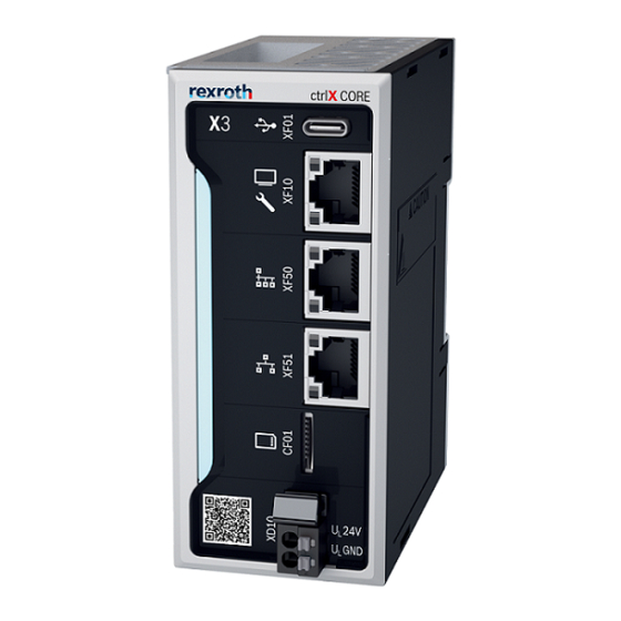
An SD card can be used to load an image to the control. All existing data is deleted when loading a new image. Please contact the Bosch Rexroth Service. Please back up the user data before you delete it if you want to restore it on another control. - Page 36 CORE control Fig. 18: Device view of the ctrlX CORE X2 and ctrlX CORE X3 ① HMI and engineering port ⑤ QR code (references to the Bosch Rexroth ② Field bus master (Ethercat) product catalog) ③ 1 GBit/s Ethernet (configurable), not ena- ⑥...
-
Page 37: Status Displays
③ 1 GBit/s Ethernet (configurable) ➇ PF30 NET ST LED ④ ctrlX CORE status LED ➈ Field bus slaves ⑤ QR code (references to the Bosch Rexroth ➉ Voltage supply product catalog) 12.2 Status displays A status display on the front panel of the controls ctrlX CORE X2 and ctrlX CORE X3 is used for error diagnostics. -
Page 38: Status Display At The Power Connector Xd10 Ctrlx Core X2 And Ctrlx Core X3
12.2.2 Status display at the power connector XD10 ctrlX CORE PLUS The voltages U and U applied at the connecting points are signaled via an own green LED next to the respective red pusher. Off = Voltage not present On = Voltage present Bosch Rexroth AG R911405645, Edition 05... -
Page 39: Status Display Pf30-Net-St-Led
12.4.1 Secure Boot Booting is secured by "Secure Boot". Thus, it can only be loaded by a runtime system released by Bosch Rexroth. For the kernel development, this mechanism can be unlocked using an app and the respective license. -
Page 40: Real-Time Clock
The battery is used to buffer the real-time clock if the control is disconnected from voltage. A circuit monitors the battery state. For notes on changing the battery, see ⮫ Chapter 14.3 “Battery change ” on page A discharged battery causes an incorrect system time. Bosch Rexroth AG R911405645, Edition 05... -
Page 41: License Information
(ii) in case of code licensed under the GPL v3 for as long as Bosch Rexroth offers spare parts or customer support for that product. Error causes and troubleshooting 13.1... -
Page 42: Maintenance
Maintenance work in the device is only permitted by trained staff! NOTICE If hardware or software components have to be exchanged, please contact the Bosch Rexroth Service or ensure that only skilled staff changes the respective components. 14.2 Scheduled maintenance tasks Include the following tasks into the maintenance schedule: •... -
Page 43: Type Code
Subject to export control (EU) No export license required ....................= N Special variante None ............................. = NN Robert Bosch ......................... = B1 Fig. 20: Type code 15.3 Accessories and spare parts For ordering information on accessories and spare parts, refer to the chapter “Spare parts, accessories and wear parts”. -
Page 44: Disposal
Furthermore, the products returned for disposal must not contain any undue foreign substances or external components. Send the products free of charge to the following address: Bosch Rexroth AG Electric Drives and Controls Bürgermeister-Dr.-Nebel-Straße 2 97816 Lohr am Main, Germany 16.2... -
Page 45: Service And Support
Detailed description of malfunction and circumstances • Type plate specifications of the affected products, in particular type codes and serial numbers • Your contact data (phone and fax number as well as your e-mail address) R911405645, Edition 05 Bosch Rexroth AG... -
Page 46: Index
Elektromagnetischen Verträglichkeit ..16 Emitted interference..... 12 Bosch Rexroth AG R911405645, Edition 05... - Page 47 Status display......37 Stranded cable......31 R911405645, Edition 05 Bosch Rexroth AG...
- Page 48 Bosch Rexroth AG Bgm.-Dr.-Nebel-Str. 2 97816 Lohr a.Main Germany Tel. +49 9352 18 0 Fax +49 9352 18 8400 www.boschrexroth.com/electrics R911405645 R911405645...