Table of Contents
Available languages
Available languages
Quick Links
- 1 Français
- 2 Chaudières de Type 0.9-9 / 2-13 / 2-17 / 5-25 / 10-35 / 10-50
- 3 Utilisation et Paramètrage de la Qaa 73 pour les Chaudières
- 4 Utilisation de la Qaa 73
- 5 Paramétrage de la Qaa 73
- 6 English
- 7 Using and Setting the Qaa 73 for the Boilers of Type 0.9-9/2-13/2-17/5-25/10-35/10-50
- 8 Using the Qaa 73
Chapters
Table of Contents

Related Manuals for Bosch REG 73-1


Summary of Contents for Bosch REG 73-1
- Page 1 Notice de montage REG 73-1 7716842136 7716842496...
-
Page 2: Table Of Contents
SOMMAIRE - PRESENTATION ........................3 - DESCRIPTION ......................... 3 - Chaudières de type 0.9-9 / 2-13 / 2-17 / 5-25 / 10-35 / 10-50 ........3 - Chaudières de type 10-100 ..................3 - COMPOSITION ........................3 - INSTALLATION ........................4 - RECOMMANDATIONS/MONTAGE .................. -
Page 3: I - Presentation
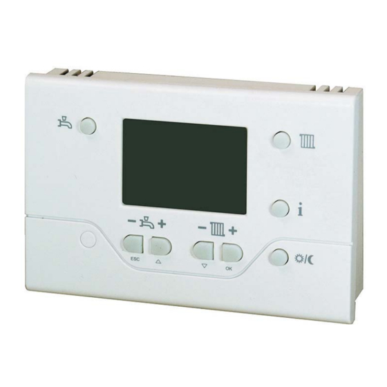
2-17 / 5-25 / 10-35 / 10-50 l’unité de gestion LMU de la chaudière (ex: pente de chauffe, plage de modulation, sys- La REG 73-1 est une sonde d'ambiance numé- tème hydraulique...). L’accès à ces paramètres rique multifonctions pour un circuit de chauffage est protégé... -
Page 4: Installation
II - INSTALLATION 1 - RECOMMANDATIONS/MONTAGE 1.1 - Recommandations - La sonde d’ambiance QAA73 doit être pla- Le câble reliant la sonde à l’unité cée dans la pièce de référence qui sera centrale de gestion LMU ne sera chauffée et non équipée de robinet thermos- pas posé... -
Page 5: Raccordement Electrique - Chaudieres Thri/Thi/Thision
INSTALLATION 2 - RACCORDEMENT ELECTRIQUE - CHAUDIERES THRi/THI/THISION - Oter le shunt (rep. 4) du connecteur (rep. 2) - raccorder la sonde QAA73 (rep. 1) au connecteur (rep. 2) et le positionner sur la borne X10-01 du LMU. Pour un simple circuit : - Enlever le shunt et son connecteur (rep. -
Page 6: Raccordement Electrique - Chaudieres Zem
INSTALLATION 3 - RACCORDEMENT ELECTRIQUE - CHAUDIERES ZEM - raccorder le connecteur 2 pts (4) au câble de - ôter le connecteur 2 pts (16) et son shunt de l’appareil d’ambiance QAA 73 puis la borne TT du tableau de commande - connecter sur la borne QAA du tableau de la consigne chauffage sera alors donnée par commande,... - Page 7 Installations instructions REG 73-1 7716842136 7716842496...
- Page 8 CONTENT - PRESENTATION ........................3 - DESCRIPTION ......................... 3 - Boilers of type 0.9-9 / 2-13 / 2-17 / 5-25 / 10-35 / 10-50 ..........3 - Boilers of type 10-100 ....................3 - COMPONENTS ........................3 - INSTALLATION ........................4 - RECOMMENDATIONS / MOUNTING..................
-
Page 9: I - Presentation
5-25 / 10-35 / 10-50 these settings is protected by a code and reser- ved only for a qualified professional The REG 73-1 is a digital multifunction room sensor for one heating circuit and for controlling The optimisation functions provide energy sa- the domestic hot water. -
Page 10: Installation
II - INSTALLATION 1 - RECOMMENDATIONS / MOUNTING 1.1 - Recommendations - The room sensor QAA73 must not be fitted in The cable connecting the sensor to the main reference room, which will be hea- the LMU management unit mut not ted but not fitted with a temperature control. -
Page 11: Electrical Connections - Thri/Thi/Thision Boilers
INSTALLATION 2 - ELECTRICAL CONNECTIONS - THRI/THI/THISION BOILERS - Remove the shunt (4) from the connector (2), - Connect the QAA 73 sensor (1) to connector (2) and place it on the X10-01 terminal of the LMU while making sure the terminals connections are correct. -
Page 12: Electrical Connections - Zem Boilers
INSTALLATION 3 - ELECTRICAL CONNECTIONS - ZEM BOILERS - Connect the 2-pin connector (4) to the - remove the 2-pin connector (16) and its QAA 73 room sensor cable then connect it to shunt from the TT terminal of the control pa- the QAA terminal on the control panel, nel - the heating setting will then be provided by... - Page 13 Montage Anleitung REG 73-1 7716842136 7716842496...
- Page 14 INHALT - ÜBERSICHT ..........................3 - BESCHREIBUNG ........................3 - Heizkessel des Typs 0.9-9 / 2-13 / 2-17 / 5-25 / 10-35 / 10-50 ........3 - Heizkessel des Typs 10-100 ..................3 - AUFBAU ........................... 3 - INSTALLATION ........................4 - EMPFEHLUNGEN / MONTAGE....................
-
Page 15: I - Übersicht
2-17 / 5-25 / 10-35 / 10-50 wichtigsten in der Steuereinheit LMU program- mierten Vorgaben (z.B.: Heizkennlinie, Modula- Der REG 73-1 ist ein digitaler Multifunktions- tionsbandbreite, Hydrauliksystem usw.). Diese Raumtemperaturfühler zur Steuerung von ein Parameter sind durch einen Code verschlüsselt Heizkreislauf und zur Steuerung der Warmwas- und können nur von einem Fachmann verstellt... -
Page 16: Installation
I - INSTALLATION 1 - EMPFEHLUNGEN / MONTAGE 1.1 - Empfehlungen - Den Raumtemperaturfühler QAA73 in einem Das Kabel zwischen Fühler und Bezugsraum mit Heizkörper ohne thermos- BMU darf weder parallel noch im tatisches Ventil anbringen. Anderenfalls gleichen Kabelkanal wie das 230-V- muss der Parameter AMBON (Raumtempe- Netzkabel verlegt werden (empfo- ratureinfluss) ausgeschaltet werden (s. -
Page 17: Stromanschluss - Thri/Thi/Thision Heizkesseln
INSTALLATION 2 - STROMANSCHLUSS - THRI/THI/THISION HEIZKESSELN - Die Abzweigung (4) an Stecker entfernen, - Den Fühler QAA 73 (1) mit dem Stecker (2) Klemme X10-01 anschließen. Für einen einfachen Kreislauf: - Den Shunt mit Stecker (3) von der Klemm- leiste X10-02 entfernen. -
Page 18: Stromanschluss - Zem Heizkesseln
INSTALLATION 3 - STROMANSCHLUSS - ZEM HEIZKESSELN - Den 2-poligen Stecker (4) zunächst an das - 2-poligen Steckverbinder (16) mit Shunt von Kabel des Raumtemperaturgeräts QAA 73 der TT-Klemme am Bedienfeld abnehmen - und dann an die QAA-Klemme auf dem Be- der Heizsollwert wird dann vom Raumtem- dienfeld anschließen. - Page 19 NOTIZEN - 7 -...
- Page 20 Bosch Thermotechnologie SAS CS 80001 F-29410 Saint-Thégonnec www.bosch-climate.fr...