
Related Manuals for Bosch FHP560


Summary of Contents for Bosch FHP560
- Page 1 FHP560 Multi-Protocol Heat Pump Controller For integration with systems running industry standard protocols Applications Manual...
-
Page 2: Table Of Contents
5 - DDC controls by others will receive unit status alarm (error / no error) but won’t be able to interpret the fault code - must use Bosch DDC to get cause of error 11 Common Applications fault codes to BAS. -
Page 3: Fhp560 Overview
Flexible and easily configured software package for options including: the most widely used protocols including: BACnet MS/TP, N2, Modbus, and LON (requires additional hardware). The FHP560 may be run either in stand-alone operation mode, or with the DDC network by integrating with a BAS. -
Page 4: Specifi Cation
(W x H x D): Mounting Hole Dimensions Two mounting holes located center line of controller with 5-9/16” (141mm) vertical spacing Table 1 Fig. 2 FHP560 Controller Dimensions in Inches (mm) Data subject to change Page____ of ____ Bosch Thermotechnology Corp. -
Page 5: Controller Components & Features
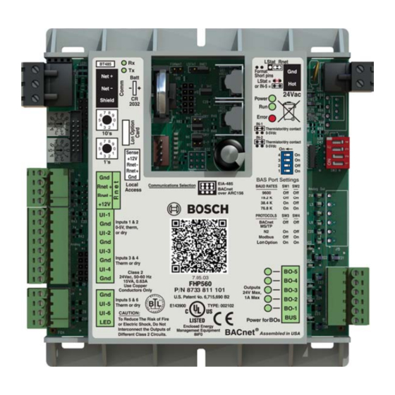
Outputs: The FHP560 has fi ve (5) binary outputs that can each be connected to a maximum of 24Vac/26Vdc. Each output is a dry contact is turned on. In the example shown in Fig. 4, the rotary dial is set to address 69. -
Page 6: Explanation Of Ddc Options
Please consult the applications department when including this option as an engineering add-on. 0-5V CO₂ sensor, or from CO₂ values pushed to the FHP560 over a network. A damper end switch connected to the FHP560 may be used to verify damper status and disable compressor operation when the damper fails. -
Page 7: O Port Assignments And Overview
The factory-installed zone valve is normally-closed and is indexed to open by the FHP560 when there's a call This input is used if RH readings are not desired from a ZS Combo sensor or over Valve End Switch for heating or cooling. - Page 8 8 | FHP560 Controller Applications Manual Universal Inputs Binary Outputs Port Inputs Accepted Signal Type Jumper Position Overview Port Outputs Accepted Signal Type Signal Label Overview Binary Output 1 is factory reserved for the fan command (G) and is wired to the The normally-open contacts of a fi...
-
Page 9: Wiring Termination Specs
Applications Manual FHP560 Controller | 9 8 Wiring Termination Specs Bosch Thermotechnology Corp. Page____ of ____ Data subject to change... -
Page 10: Electrical Schematic
1 0 | FHP560 Controller Applications Manual 9 Electrical Schematic Rnet BT485 Format Short pins Lstat Net + IN-5 Net - Batt 24 Vac Power POWER Shield Error IN-1 ERROR 2032 Thermistor/dry contact 0-5Vdc Thermistor/dry Sense contact +12V 0-5Vdc IN-2... -
Page 11: Symbol Legend
Applications Manual FHP560 Controller | 11 10 Symbol Legend 10.1 Common Abbreviations Abbreviations AFMS Air Flow Measuring Station Modulating Air Conditioning Normally Closed Air Conditioning Unit Normally Open Air Handling Unit Outdoor Air Analog Input Outdoor Air Damper Analog Output... -
Page 12: Common Applications
1 2 | FHP560 Controller Applications Manual 11 Common Applications Heat Pump Sequence of Operation – HP Basic Supply Fan Start/Stop: WARNING: The supply fan will be started according to the schedule. After the supply fan has been started the control sequence will be enabled. Fan 11.1 HP Basic... -
Page 13: Hp + Hgrh
Applications Manual FHP560 Controller | 13 11.2 HP + HGRH Heat Pump Sequence of Operation – HP + HGRH Supply Fan Start/Stop: The supply fan will be started according to the schedule. After the supply fan has been started the control sequence will be enabled. -
Page 14: Straight Cool + Eh
1 4 | FHP560 Controller Applications Manual 11.3 STRAIGHT COOL + EH Heat Pump Sequence of Operation – STRAIGHT COOL + EH Supply Fan Start/Stop: The supply fan will be started according to the schedule. After the supply fan has been started the control sequence will be enabled. -
Page 15: Straight Hp + Cwv
Applications Manual FHP560 Controller | 15 11.4 STRAIGHT HP + CWV Heat Pump Sequence of Operation – HP + CWV Supply Fan Start/Stop: The supply fan will be started according to the schedule. After the supply fan has been started the control sequence will be enabled. -
Page 16: Hp + Lp
1 6 | FHP560 Controller Applications Manual 11.5 HP + LP Heat Pump Sequence of Operation – HP + LP Supply Fan Start/Stop: The supply fan will be started according to the schedule. After the supply fan has been started the control sequence will be enabled. -
Page 17: Hp + Boilerless
Applications Manual FHP560 Controller | 17 11.6 HP + BOILERLESS Heat Pump Sequence of Operation – HP + BOILERLESS Supply Fan Start/Stop: The supply fan will be started according to the schedule. After the supply fan has been started the control sequence will be enabled. -
Page 18: Hp + Economizer
1 8 | FHP560 Controller Applications Manual 11.7 HP + ECONOMIZER Heat Pump Sequence of Operation – HP + ECONOMIZER Supply Fan Start/Stop: The supply fan will be started according to the schedule. After the supply fan has been started the control sequence will be enabled. -
Page 19: Straight Cool + Economizer
Applications Manual FHP560 Controller | 19 11.8 STRAIGHT COOL + ECONOMIZER Heat Pump Sequence of Operation – STRAIGHT COOL + ECONOMIZER Supply Fan Start/Stop: The supply fan will be started according to the schedule. After the supply fan has been started the control sequence will be enabled. -
Page 20: Hp + Damper + Co₂
2 0 | FHP560 Controller Applications Manual 11.9 HP + DAMPER + CO₂ Heat Pump Sequence of Operation – HP + DAMPER + CO₂ Supply Fan Start/Stop: The supply fan will be started according to the schedule. After the supply fan has been started the control sequence will be enabled. -
Page 21: Hp + Boilerless + Dps
Applications Manual FHP560 Controller | 21 11.10 HP + BOILERLESS + DPS Heat Pump Sequence of Operation – HP + BOILERLESS + DPS Supply Fan Start/Stop: The supply fan will be started according to the schedule. After the supply fan has been started the control sequence will be enabled. -
Page 22: Hp + Boilerless + Hgrh + (Sds-Sdp)
2 2 | FHP560 Controller Applications Manual 11.11 HP + BOILERLESS + HGRH + (SDS-SDP) Heat Pump Sequence of Operation – HP + BOILERLESS + HGRH + (SDS-SDP) Supply Fan Start/Stop: The supply fan will be started according to the schedule. After the supply fan has been started the control sequence will be enabled. -
Page 23: Hp + Economizer + Hgrh + (Sds-Fss-Dfs)
Applications Manual FHP560 Controller | 23 11.12 HP + ECONOMIZER + HGRH + (SDS-FSS-DFS) Heat Pump Sequence of Operation – HP + ECONOMIZER + HGRH + (SDS-FSS-DFS) Supply Fan Start/Stop: The supply fan will be started according to the schedule. After the supply fan has been started the control sequence will be enabled. -
Page 24: Hp + Eh + Cwv + (Sds-Fss-Ves)
2 4 | FHP560 Controller Applications Manual 11.13 HP + EH + CWV + (SDS-FSS-VES) Heat Pump Sequence of Operation – HP + EH + CWV + (SDS-FSS-VES) Supply Fan Start/Stop: The supply fan will be started according to the schedule. After the supply fan has been started the control sequence will be enabled. -
Page 25: Hp + Hgrh + Lp + (Dfs-Pss)
Applications Manual FHP560 Controller | 25 11.14 HP + HGRH + LP + (DFS-PSS) Heat Pump Sequence of Operation – HP + HGRH + LP + (DFS-PSS) Supply Fan Start/Stop: The supply fan will be started according to the schedule. After the supply fan has been started the control sequence will be enabled. -
Page 26: Water-To-Air Sequence Of Operation
2 6 | FHP560 Controller Applications Manual 12 Water-To-Air Sequence Of Operation Heating / Cooling Operation The setpoints are compared to the effective zone temperature from the selected source. Demand, based on a PID algorithm, is used to determine when to energize the unit in either heating or cooling mode. The PID algorithm calculates the demand value as a percentage (%) Unit Start-Up based on the difference between the zone temperature and the heat/cool setpoints. - Page 27 Applications Manual FHP560 Controller | 27 Options Smoke Detector Switch: Auxiliary Electric Heat: A fi eld installed smoke detector provides a contact closure at the confi gured input (IN-5 or IEM) during a smoke event, and will initiate Electric Heat (EH) option may be factory or fi eld installed and must be confi gured by the equipment integrator. Only one (1) stage of auxiliary emergency shutdown procedures after 5 seconds (no time delay if network point is used for shutdown instead of switch).
-
Page 28: Integration Points List - Water-To-Air Standard Software
2 8 | FHP560 Controller Applications Manual 13 Integration Points List - Water-to-Air Standard Software 7.05.03 Integration Points BACnet MODBUS Point Description Read Integration Points Description Name Only Type SNVT Object Name Register Type Name SNVT Type BACnet MODBUS Point Description... - Page 29 Applications Manual FHP560 Controller | 29 Integration Points Integration Points BACnet MODBUS BACnet MODBUS Point Description Read Point Description Read Description Description Name Only Name Only Type Object SNVT Type Object SNVT Name Register Type Name SNVT Name Register Type...
- Page 30 3 0 | FHP560 Controller Applications Manual Integration Points Integration Points BACnet MODBUS BACnet MODBUS Point Description Read Point Description Read Description Description Name Only Name Only Type Object SNVT Type Object SNVT Name Register Type Name SNVT Name Register...
- Page 31 Applications Manual FHP560 Controller | 31 Integration Points Integration Points BACnet MODBUS BACnet MODBUS Point Description Read Point Description Read Description Description Name Only Name Only Type SNVT Type SNVT Object Object Name Register Type Name SNVT Name Register Type...
- Page 32 3 2 | FHP560 Controller Applications Manual Integration Points Integration Points BACnet MODBUS BACnet MODBUS Point Description Read Point Description Read Description Description Name Only Name Only Type Object SNVT Type Object SNVT Name Register Type Name SNVT Name Register...
- Page 33 Applications Manual FHP560 Controller | 33 Integration Points Integration Points BACnet MODBUS BACnet MODBUS Point Description Read Point Description Read Description Description Name Only Name Only Type SNVT Type SNVT Object Object Name Register Type Name SNVT Name Register Type...
- Page 34 3 4 | FHP560 Controller Applications Manual Integration Points Integration Points BACnet MODBUS BACnet MODBUS Point Description Read Point Description Read Description Description Name Only Name Only Type Object SNVT Type Object SNVT Name Register Type Name SNVT Name Register...
- Page 35 Applications Manual FHP560 Controller | 35 Integration Points BACnet MODBUS Point Description Read Description Name Only Type Object SNVT Name Register Type Name SNVT Type Must be set to enable Valve End Switch feature when using IEM Enable/Disable Valve allow_VES_alrm_1...
-
Page 36: Zs Combination Sensors
Standard Zone Sensor, w/ Humidity FHP Logo 8 733 933 903 The Bosch line of intelligent zone sensors provides the function and fl exibility you need to manage the conditions important to the comfort and ZSPL -FHP Plus Zone Sensor with override, slide pot and occupied LED no options FHP Logo 8 733 933 901 productivity of the zone occupants. -
Page 37: Zs Sensor Dimensions
The FHP ZS Combo Sensors are thermistor-based, communicating temperature sensors that may optionally sense humidity or CO₂. The ZS Sensors are fi eld installed and are wired to the Rnet port of the FHP560 controller. A maximum of 5 ZS sensors may be daisy-chained and used for applications where multiple readings for temperature, humidity or CO₂... -
Page 38: Addressing Sensors
14.8 ZS Sensor Wiring Specifi cation When multiple FHP ZS Combo Sensors (up to 5 max) are connected to the FHP560 controller, each sensor on the Rnet must have a unique address associated with it, and the addresses have to be sequential. If the sensors are not addressed sequentially the FHP560 reads any gaps as faulty sensors and a sensor wiring alarm is generated. -
Page 39: Wiring And Mounting A Zs Sensor
Applications Manual FHP560 Controller | 39 14.9 Wiring and Mounting a ZS Sensor CAUTION: Allow no more than .06 inch (1.5 mm) bare communication wire to protrude. If bare WARNING: communication wire contacts the cable’s foil shield, The Rnet cable is wired to the controller. Before wiring... -
Page 40: Electrical Schematic - Sensor Averaging
4 0 | FHP560 Controller Applications Manual 14.10 Electrical Schematic - Sensor Averaging Rnet BT485 Format Short pins Net + Lstat IN-5 Net - Batt 24 Vac Power POWER Shield Error IN-1 ERROR 2032 Thermistor/dry contact 0-5Vdc Thermistor/dry Sense contact... -
Page 41: Zs Pro Sensors
The value shown is percent relative humidity. Make the zone warmer or cooler by adjusting the setpoint. By default the FHP560 only allows a temperature change of 3 degrees in either direction (cooler or warmer) but this value can be changed using a BACview interface or from the BAS. - Page 42 Press the or button to adjust the zone temperature setpoint. The control program determines how much you can adjust the setpoint and is default to +/- 3°F. The FHP560 control program allows this adjustment value to be changed either using a BACview interface or from an available BAS.
-
Page 43: Rnet Tags
Below is a list of information provided by the ZS Pro Combo Sensor when the info button is pressed: FHP560 Input/Output in MANUAL lock position Wired Sensor Failure for ZS Sensor, DAT Sensor, LWT Sensor, Humidity Sensor or CO₂ Sensor... -
Page 44: The Bacview Interfaces
15.2 Virtual BACview Virtual BACview provides the end-user an interface to the FHP560 by way of a laptop and a purchased USB interface cable (8733927403). Once The BACview is a Human-Machine Interface (HMI) that interfaces with the FHP560 controller, enabling the user to view and change property the cable is purchased, the corresponding driver will need to be downloaded and installed before using the software. -
Page 45: Bacview Dimensions And Specifi Cations
Applications Manual FHP560 Controller | 45 15.3 BACview Dimensions and Specifi cations 15.4 Rnet Wiring Specifi cations Fig. 25 Rear View of Hand-Held Module Use the specifi ed type of wire and cable for maximum Fig. 24 Dimensions in inches (mm) signal integrity. -
Page 46: Connecting The Bacview To Fhp560
Connect the BACview module (or laptop if using Virtual BACview) to the serial port on the DDC controller, or to a ZS wall-mounted sensor In lieu of using the hand-held module to interface with the FHP560, a connection may be established at the local access port of the controller, or at connected to the controller (See Fig 26). -
Page 47: Troubleshooting
Wiring connections may be inaccurate. Verify sensor is wired as specified on pages 38 and 39 of this document, and that all conductors are secure and continuous. The FHP560 controller software may be corrupted. Verify controller operating status and perform battery ... - Page 48 United States and Canada Bosch Thermotechnology Corp. 50 Wentworth Avenue Londonderry, NH 03053 Tel: 1-866-642-3198 Fax: 1-603-965-7581 www.bosch-climate.us ® BTC 761601101 A | 06.2015...