
Related Manuals for Bosch Worcester TDS 10


Summary of Contents for Bosch Worcester TDS 10
- Page 1 TDS 10 SOLAR SYSTEM CONTROLLER FOR WORCESTER SOLAR HEATING SYSTEMS INSTALLATION, USER INSTRUCTIONS & CUSTOMER CARE GUIDE...
-
Page 2: Table Of Contents
Contents Contents Product details Operation Intended use General information Standard package Controls Technical data Settings Description of function 5.3.1 Storage tank Key to illustrations in temperature limit Appendix 5.3.2 Manual mode Unvented DHW 5.3.3 Viewing temperature Cylinders readings 5.3.4 Power failure Regulations Maintenance Installation... - Page 3 Safety precautions Safety precautions Symbols B To ensure the equipment functions Safety instruc- properly, always follow the instruc- tions in this docu- tions in this manual. ment are identified B This accessory may only be fitted by by a warning-trian- an approved installer and must not gle symbol and are be commissioned until the solar...
-
Page 4: Product Details
Product details Product details The TDS 10 is a controller for use with Technical data thermal solar heating systems that use Device dimensions heat from the sun to heat a hot water (LxWxH) 136x133x37 mm tank or intermediate heat store. Weight 250 g Power supply... -
Page 5: Description Of Function
Product details Description of function Storage tank temperature limiter The storage tank temperature limiter For a simplified diagram of the system, prevents the domestic hot water refer to Figure 2 on page 16. becoming too hot: Temperature differential regulator Normal setting = 60°C. -
Page 6: Key To Illustrations In Appendix
Product details Solar panel high-temperature cut- Key to illustrations in out (fixed setting) Appendix • Above a temperature of 130 °C at Key to Figures 1 to 10 on pages 16 the solar panel temperature sensor to 18: the solar heating system pump Solar heating system pump Solar panel temperature sensor switches off. -
Page 7: Regulations
Regulations Regulations This accessory conforms to the rele- The installation of the Worcester Solar vant EN regulations. System and controller must be carried out in accordance with the relevant The following regulations and require- requirements for safety, current ments must be observed: IEE wiring regulations, local building •... -
Page 8: Installing The
Installation B Wiring run lengths and cross-sec- Installing the tempera- tional areas for low-voltage wiring: ture sensors Length up to 50 m 0.75 mm Use only genuine PTC- type temperature sen- Length up to 100 m 1.5 mm sors (see Section 1.3). Table 3 B For the 230 V power supply use To install immersion sensors... -
Page 9: Commissioning
Commissioning Cable exits to rear: Commissioning Break open with a suitable tool through the programmer casing Check that the solar backplate (Fig. 6). heating system has been filled and vented On fine wire leads: according to the in- structions for the solar B Use cable-end panel and the solar sleeves. -
Page 10: Operation
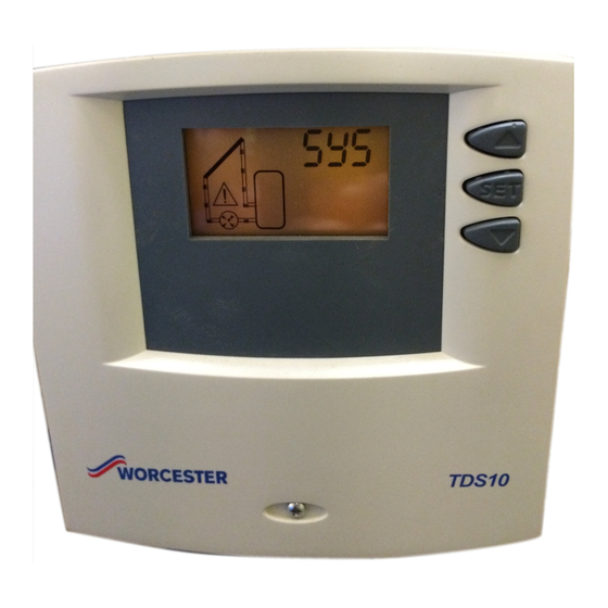
Operation Operation Controls For overview of controls, see Fig. 1 on Information to be given page 16. to the user by the in- staller: B Explain to the user how to operate the controller. S set to E.g. 48 °C B Give the user all the automatic moves / stops... -
Page 11: Settings
Maintenance Settings – The display backlighting is red, ON flashes and the symbol 5.3.1 Storage tank temperature moves (Fig. 12). limit 5.3.3 Viewing temperature read- B Press and hold the button for ings approx. 2 seconds until the flashing B Pressing the button symbol max appears on the dis-... -
Page 12: Troubleshooting
Troubleshooting Troubleshooting Faults indicated on the display Display shows (flashing red/yellow) Cause Remedy Short circuit on sensor lead to Check sensor lead solar panel temperature sen- Short circuit on sensor lead to Check sensor lead solar panel temperature sen- Break in sensor lead to solar Check sensor lead panel temperature sensor Break in sensor lead to solar... - Page 13 Troubleshooting Display shows (flashing red/yellow) Cause Remedy Indication of a fault in the sys- Check that the shut-off tem, e.g. shut-off valves valves are open. closed, air in the system or Check the system. defective solar heating system If necessary have the sys- pump.
-
Page 14: Faults Not Indicated On The Display
Troubleshooting Faults not indicated on the display Problem Cause Remedy Display blank, solar heating No power supply, fuse blown Have electrical system system pump not running even or power lead defective. checked by qualified though storage tank tempera- electrician. ture is below solar panel tem- perature. - Page 15 Troubleshooting Problem Cause Remedy Solar heating system pump Break in connecting lead to Check lead. not running even though solar heating system pump or symbol on the display is mov- lead not connected. ing. Fuse (SI, Fig. 10) has blown. Check fuse and replace if necessary.
- Page 16 Troubleshooting Appendix Fig. 1 TDS 10 6 720 611 675-18.1J Fig. 2 Fig. 4 Fig. 3 Fig. 5 6 720 612 217 (05.03)
- Page 17 Troubleshooting 6 mm 6 mm 3,5 mm Fig. 6 Fig. 7 6 720 612 217 (05.03)
- Page 18 Troubleshooting Fig. 9 Fig. 8 230V AC Fig. 10 6 720 612 217 (05.03)
- Page 19 Troubleshooting Fig. 11 Fig. 12 Fig. 13 6 720 612 217 (05.03)
-
Page 20: Appendix
USER INSTRUCTIONS & CUSTOMER CARE GUIDE Worcester, Bosch Group Cotswold Way, Warndon, Worcester WR4 9SW. Tel. 01905 754624 Fax. 01905 754619 www.worcester-bosch.co.uk Worcester Bosch Group is a trading name of BBT Thermotechnology UK Ltd. 6 720 612 217 (05/03) OSW...