Table of Contents
Quick Links
Table of Contents

Related Manuals for AMGO BP-10


Summary of Contents for AMGO BP-10
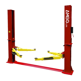
- Page 1 TWO-POST LIFT Model: BP-10...
-
Page 2: Table Of Contents
CONTENTS Product Features and Specifications ............1 Installation Requirement ................3 Steps of Installation ………………………………………………………..…………....4 Exploded View ..................17 Test Run .....................20 Operation Instruction ................21 Maintenance ..................22 Trouble Shooting .................23 Parts List ………..................24... -
Page 3: Product Features And Specifications
· Self-lubricating UHMW Polyethylene sliders and bronze bush. · Single-point safety release, and dual safety design. · Super-symmetric arms design, make lifts easily find the lift point of the car. · Stackable adapters 1.5”, 2.5”, 5” as standard. Fig.1 MODEL BP-10 SPECIFICATIONS Width Minimum Lifting Lifting... - Page 4 Arm Swings View 100 错 误 ! 未 Fig. 2...
-
Page 5: Installation Requirement
II. INSTALLATION REQUIREMENT A. TOOLS REQUIRED Rotary Hammer Drill ( 3/4” ) Carpenter’s Chalk Screw Sets Hammer Tape Measure(295”) Level Bar Pliers English Spanner (12") Socket Head Wrench ( 6 Ratchet Spanner With Socket (28 ... -
Page 6: Steps Of Installation
B. SPECIFICATIONS OF CONCRETE (See Fig. 4) Specifications of concrete must be adhered to the specification as following. Failure to do so may result in lift and/or vehicle falling. 1. Concrete must be thickness minimum and without reinforcing steel bars,and must be dried completely before the installation. - Page 7 Check the parts before assembly 1.Packaged lift and hydraulic power unit (See Fig. 6) Fig. 6 2. Move the lift aside with a fork lift or hoist, and open the outer packing carefully, take off the parts from upper and inside the column, take out the parts box,check the parts according to the shipment parts list (See Fig.
- Page 8 5. Open the parts bag and check the parts according to parts box list (See Fig. 10). Fig. 10 D. Lay down two columns on the installation site parallelly, position the power-side column according to the actual installation site. Usually, it is suggested to install Power side column on the front-right side from which vehicles are driven to the lift.
- Page 9 E. Connecting cables (See Fig. 12) 1.Put down columns and then push the carriages higher than chain pulley。 b:Push the carriages higher than chain pulley, cable pass through the top of the carriages and pass through the hole of the bottom steel plate of carriages c: Pull out cable a: Let the cable rope into the carriage.
- Page 10 F. Position columns and install safety device (See Fig. 14). Check the columns plumbness with level bar, and adjusting with the shims if the columns are not vertical. Check the columns plumbness with level bar on front and side column Fig.
- Page 11 Bolting . Lift the carriages up by hand and make them be locked at the same level (See Fig.17) Fig. 17...
- Page 12 I. Install cables (See Fig.18) Let the cable cross over the hole which on the top plate of the carriages, and to be screwed the nuts at the end of the cable. Fig. 18...
- Page 13 Connecting oil hose (See Fig. 19) Fig. 19...
- Page 14 K. Install power unit and oil hose (See Fig. 20) Tighten all the hydraulic fittings, and fix the oil hose by retainer. Use 19 Wrench to tighten the nut after installing the fitting of power unit Fig. 20 Fix the oil hose by Retainer...
- Page 15 L. Install safety cable Install safety cable from offside safety lock to power-side safety lock (See Fig. 21) Connecting direction safety cable View A View B Fig. 21...
- Page 16 Install floor cover ( See Fig. 22). Floor cover Fig. 22 N. Install lifting arms and adjust the arm locks 1. Install the lifting arms (See Fig. 23) 2. Lowing the carriages down to the lowest position, then use the wrench to loosen the nut of arm lock (See Fig.
- Page 17 Note: 1. For the safety of operators, the power wiring must contact the floor well. 2. Pay attention to the direction of rotations when using three phase motors. AMGO single phase motor (See Fig. 27). 1. Connecting the two power supply lines (active wire L and neutral wire N) to terminals of AC contactor marked L1, L2 respectively.
- Page 18 Fig. 27 AMGO 3 phase motor 1、 Circuit diagram(See Fig. 28). Three phase Fig. 28 2. Connection step (See Fig. 29) a. The source wires L1, L2, L3 connected with terminals of AC contactor marked L1, L2, L3 respectively. b. Terminals of AC contactor marked L1 connected with terminals 4# of control button;...
-
Page 19: Exploded View
IV. EXPLODED VIEW Model BP-10 direction Fig. 30... - Page 20 Cylinder Fig. 31 AMGO MANUAL POWER UNIT 220V/50HZ/1 Phase 380V/50HZ/3 phase...
- Page 21 Fig. 32 Illustration of hydraulic valve for AMGO power unit AMGO manual power unit, 220V/50HZ, Single phase (See Fig. 33) Oil return port Relief valve Release valve Throttle valve Handle for Release Oil Outlet valve Check valve Fig. 33...
-
Page 22: Test Run
V. TEST RUN 1. Adjust synchronous cable (See Fig. 35) Press UP button to lift the carriage up to the position of the cable nut higher than chain pulley. Use wrench to hold the cable fitting, meanwhile Cable Nut use ratchet spanner to tighten the cable nut. Make sure two cables are in the same tension so that two lifting carriages can work synchronously. -
Page 23: Operation Instruction
4. Test with load After finishing the above adjustment, test running the lift with load. Run the lift in low position for several times first, make sure the lift can rise and lower synchronously, the safety device can lock and release synchronously. And then test run the lift to the top completely. -
Page 24: Maintenance
where manufacturers recommended 7. Push button “UP” until the lift pads contact underside of vehicle totally. Recheck to make sure vehicle is secure; 8. Continue to raise the lift slowly to the desired working height, ensuring the balance of vehicle; 9. -
Page 25: Trouble Shooting
VIII.TROUBLE SHOOTING TROUBLE CAUSE REMEDY 1. Button does not work 1. Replace button 2. Wiring connections are not in good 2.Repair all wiring connections Motor does not condition 3. Motor burned out 3. Repair or replace motor 4. AC contactor burned out 4. -
Page 26: Parts List
Model BP-10 PARTS LIST FOR Item Part# Description Qty. Note (See Fig. 30, Fig. 21, Fig. 20, Fig. 19, Fig. 18) 203141 Power-side Column 209011 Plastic Pulley 209010 Snap Ring 209008 Safety Cover 209009 Cup Head Bolt 206006 Washer 206023A... - Page 27 206045 Protective Rubber Item Part# Description Qty. Note 206046 Self-tapping Screw 206156 Tool tray 206032 Snap Ring 209022 Washer 217044 Arm Lock 206154 Rear Toe Guard 217046A Arm Lock Bar(Left) 206036 Hair Pin 217045 Spring 206155 Front Toe Guard 203131 Rear arm(drop-in) Rear Outer Arm 203149...
- Page 28 420049 Split Pin Item Part# Description Qty. Note Stackable Adapter(1.5") 209051B 209052B Stackable Adapter(2.5") 209053B Stackable Adapter(5") 209059B Anchor Bolt 620065 Shim(2mm) 201090 Shim(1mm) 203069 Cable 209066 Cable nut 207024 900 fitting 201082 Extend straight fitting L=98mm 420097 900fitting 203107 Oil hose 211016 T fitting...
- Page 29 Parts for AMGO manual power unit 220V/50HZ/1Phase (See Fig. 32) Item Part# Description Qty. Note 201-1 81400287 Motor 201-2 81400363 Motor Connecting Shaft 201-3 81400362 Manifold Block 201-4 81400266 Relief Valve 201-5 81400268 Throttle Valve 201-6 209149 Lock Washer 201-7...
- Page 30 AMGO HYDRAULIC CORPORA 1931 Jo Rogers Blvd, Manning, South Carolina, Zip:29102 Tel: (803) 505-6410 fax: (803) 505-6410 72122703 04/2017...