Mitsubishi Electric Melsec Q Series User Manual
Programmable contoller
mes interface module
Hide thumbs
Also See for Melsec Q Series:
- User manual (834 pages) ,
- Reference manual (674 pages) ,
- Programming manual (624 pages)

Related Manuals for Mitsubishi Electric Melsec Q Series


Summary of Contents for Mitsubishi Electric Melsec Q Series
- Page 1 MES Interface Module User's Manual -QJ71MES96N -QJ71MES96 (MX MESInterface) -SW1DNC-MESIF-E...
-
Page 3: Safety Precautions
SAFETY PRECAUTIONS (Always read these precautions before using this equipment.) Before using this product, please read this manual and the relevant manuals introduced in this manual carefully and pay full attention to safety to handle the product correctly. The precautions given in this manual are concerned with only this product. For the safety precautions of the programmable controller system, please read the User's Manual for the CPU module used. - Page 4 [Design Precautions] WARNING When the programmable controller system security needs to be protected against illegal access from an external device via a network, take measures at the user's discretion. Also, when it is necessary to ensure safety of the programmable controller system against unauthorized access from any external device via the Internet, include measures such as a firewall.
- Page 5 [Installation Precautions] CAUTION Completely turn off the externally supplied power used in the system before mounting or removing the module. Not doing so could result in damage to the product. Tighten the screw in the specified torque range. Undertightening can cause a drop, short circuit or malfunction. Overtightening can cause a drop, short circuit or malfunction due to damage to the screw or module.
- Page 6 [Wiring Precautions] CAUTION Be sure there are no foreign substances such as sawdust or wiring debris inside the module. Such debris could cause fires, damage, or erroneous operation. A protective film is attached to the top of the module to prevent foreign matter, such as wire chips, from entering the module during wiring.
- Page 7 [Operation Precautions] WARNING Make sure safety before controlling a running programmable controller (e.g. data modification). Do not write any data to the "System area" in the buffer memory of the intelligent function module. As for signals output from the programmable controller CPU to the intelligent function module, never output (ON) a "Use prohibited"...
-
Page 8: Conditions Of Use For The Product
CONDITIONS OF USE FOR THE PRODUCT (1) Mitsubishi programmable controller ("the PRODUCT") shall be used in conditions; i) where any problem, fault or failure occurring in the PRODUCT, if any, shall not lead to any major or serious accident; and ii) where the backup and fail-safe function are systematically or automatically provided outside of the PRODUCT for the case of any problem, fault or failure occurring in the PRODUCT. -
Page 9: Revisions
REVISIONS The manual number is given on the bottom left of the back cover. Print date Manual number Revision Sept., 2006 SH(NA)-080644ENG-A First edition Jan., 2007 SH(NA)-080644ENG-B Correction GENERIC TERMS AND ABBREVIATIONS, DEFINITIONS AND DESCRIPTIONS OF TERMS, Chapter 1, Sections 2.2, 2.4.2, 2.5, 3.1, 3.2, 3.5, 4.2, 4.6.2, 5.2, 6.1.10, 7.7.1, 7.8.1, 7.9.1, 7.10.1, 7.11.1, 7.11.2, 7.12.5, 7.13.2, 7.13.4, 8.1, 8.2, 8.6, 10.2.1, 10.3.2, 10.3.3, Appendix 3.9 Addition... - Page 10 The manual number is given on the bottom left of the back cover. Print date Manual number Revision Jan., 2009 SH(NA)-080644ENG-H Correction Sections 2.2, 3.2, 6.1.4, 10.3.3, Appendices 1.1, 1.2 Jan., 2010 SH(NA)-080644ENG-I Correction SAFETY PRECAUTIONS, GENERIC TERMS AND ABBREVIATIONS, DEFINITIONS AND DESCRIPTIONS OF TERMS, Sections 1.1, 2.3, 2.4.2, 2.5, 2.6.2, 3.1, 3.3, 4.3, 4.7.2, 4.8.1 to 4.8.3, 6.1.6, 6.1.9, 7.3.1, 7.3.4, 7.8.1, 7.9, 7.9.1, 7.10, 7.10.1, 7.11, 7.11.1, 7.12.5, 8.1, 8.2, 8.8.1, 10.2.1, 10.2.2, 10.3.2,...
- Page 11 This manual confers no industrial property rights or any rights of any other kind, nor does it confer any patent licenses. Mitsubishi Electric Corporation cannot be held responsible for any problems involving industrial property rights which may occur as a result of using the contents noted in this manual.
-
Page 12: Table Of Contents
INTRODUCTION Thank you for purchasing the Mitsubishi MELSEC-Q series programmable controllers. Before using the equipment, please read this manual carefully to develop full familiarity with the functions and performance of the Q series programmable controller you have purchased, so as to ensure correct use. CONTENTS SAFETY PRECAUTIONS ..........................A - 1 CONDITIONS OF USE FOR THE PRODUCT....................A - 6... - Page 13 CHAPTER 3 SPECIFICATIONS 3 - 1 to 3 - 38 Performance Specifications ......................3 - 1 Accessible Devices and Ranges ..................... 3 - 5 Function List ..........................3 - 12 I/O Signals for Programmable Controller CPU ................3 - 16 3.4.1 I/O signal list ...........................
- Page 14 Uninstallation ........................... 5 - 9 CHAPTER 6 FUNCTIONS 6 - 1 to 6 - 25 DB Interface Function ........................6 - 1 6.1.1 DB interface function operation ....................6 - 1 6.1.2 Job execution procedure ......................6 - 2 6.1.3 Tag function ..........................
- Page 15 7.8.2 Setting items in Array setting....................7 - 43 7.8.3 Setting items in Component setting..................7 - 45 Server Service Setting ........................7 - 53 7.9.1 Setting items in Server Service setting ................... 7 - 54 7.10 Job Setting............................. 7 - 58 7.10.1 Setting items in Job setting.....................
- Page 16 8.8.1 Access log ..........................8 - 24 8.8.2 SQL failure log ........................8 - 29 CHAPTER 9 XML MESSAGE FORMAT 9 - 1 to 9 - 6 XML Message Format Definition ..................... 9 - 2 XML Message Format Sending Method ..................9 - 4 9.2.1 XML message format sending method ..................
- Page 17 Appendix 3.12 CONDITION.CSV ......................App - 36 Appendix 3.13 ACTION.CSV ......................App - 40 Appendix 3.14 ACFIELD.CSV......................App - 43 Appendix 3.15 ACCONDITION.CSV....................App - 45 Appendix 3.16 ACEXCEPTION.CSV ....................App - 47 Appendix 3.17 ACOPERATION.CSV ....................App - 49 Appendix 3.18 REMOTE.CSV......................App - 52 Appendix 3.19 ORDERBY.CSV ......................App - 54 Appendix 3.20 MULTISELECT.CSV ....................App - 55 Appendix 4 Processing Time........................App - 57 Appendix 4.1 QJ71MES96N ......................App - 57...
-
Page 18: Compliance With Emc And Low Voltage Directives
COMPLIANCE WITH EMC AND LOW VOLTAGE DIRECTIVES (1) Method of ensuring compliance To ensure that Mitsubishi programmable controllers maintain EMC and Low Voltage Directives when incorporated into other machinery or equipment, certain measures may be necessary. Please refer to one of the following manuals. •... -
Page 19: How To Use This Manual
HOW TO USE THIS MANUAL This manual is organized by objective for using the MES interface module and MX MESInterface Version 1 (SW1DNC-MESIF-E). Use this manual with referring to the following. (1) Features and software configuration Chapter 1 OVERVIEW Section 1.1 covers the features. Section 1.2 covers the MX MESInterface software configuration. - Page 20 (8) Setting method for DB Connection Service Chapter 8 DB CONNECTION SERVICE AND SETTING TOOL CHAPTER 8 covers the functions and setting method for the DB Connection Service. (9) XML message format Chapter 9 XML MESSAGE FORMAT CHAPTER 9 covers the XML message format. (10)Methods for checking errors and the corrective actions Chapter 10 TROUBLESHOOTING CHAPTER 10 covers troubleshooting and lists the error codes.
- Page 21 Displaying a reference Displaying a chapter title Reference in this manual and Index on the right of a page reference manual are shown clears the chapter of the page. with Displaying a section title The section in which the open page is included is clear.
-
Page 22: Generic Terms And Abbreviations
GENERIC TERMS AND ABBREVIATIONS Unless otherwise specified, this manual uses the following generic terms and abbreviations to explain the MES interface module and MX MESInterface Version 1 (SW1DNC-MESIF-E). Generic term/abbreviation Description Generic term for the A1NCPU, A0J2HCPU, A1SCPU, A1SHCPU, A1SJCPU, A1SJHCPU, A2CCPU, A2CJCPU, A2NCPU, A2NCPU-S1, A2SCPU, A2SHCPU, A2ACPU, A2ACPU-S1, ACPU A2UCPU, A2UCPU-S1, A2USCPU, A2USCPU-S1, A2USHCPU-S1, A3NCPU, A3ACPU,... -
Page 23: Definitions And Descriptions Of Terms
DEFINITIONS AND DESCRIPTIONS OF TERMS The following table shows the definitions and descriptions of the terms used in this manual. Term Description Abbreviation for Comma Separated Values Text file in which the data are aligned and set off by commas and double quotations Function temporarily stores SQL text that failed to be sent due to a communication error and DB buffering resends the text when the communications have been recovered... - Page 24 (From the previous page) Term Description Generic term for the services can be offered by a server computer to which DB Connection Service is installed Server service There are database server service and application server service. The database server service is a service for accessing a database. The application server service is a service for linking with a program.
-
Page 25: Packing List
(From the previous page) Term Description When trigger conditions (conditions for data transmission) of multiple jobs are met in a concentrated manner, their data and trigger times are buffered in the module's internal memory so Trigger buffering that actions (data operation/transmission) can be executed later using the buffered data. Even if the frequency of data transmission triggers is high, jobs are executed without missing any trigger. -
Page 26: Chapter 1 Overview 1 - 1 To
OVERVIEW CHAPTER 1 OVERVIEW This manual explains the specifications, preparatory procedures, functions, and troubleshooting for the MELSEC-Q series MES interface module. When applying the following program examples to the actual system, make sure to examine the applicability and confirm that it will not cause system control problems. The MES interface module links the programmable controller (Production equipment) device data with information system (Manufacturing Execution System) database without communication gateways. -
Page 27: Features
OVERVIEW 1.1 Features This section explains the features of MX MESInterface. (1) Connection with the information system is enabled by simple settings without program Access to information system databases can be realized simply by making the necessary settings with the setting tool. There is no need to write programs for accessing databases, so the engineering costs for system construction can be reduced and the work period can be shortened. - Page 28 OVERVIEW (2) The information system load can be reduced. Data can be monitored on the MES interface module side and when the conditions are met, the data can be sent to the information system. Also, the data can be operated and the results of the operations can be sent to the information system.
- Page 29 OVERVIEW (3) Buffering function for reliable data acquisition/transmission (a) Even if the frequency of data transmission triggers is high, no trigger will be missed. (Trigger buffering function) When multiple sets of conditions for data transmission are met in a concentrated manner, their data and trigger times can be buffered in the module's internal memory.
- Page 30 OVERVIEW (b) Data to be send to the database are protected even if a communication error occurs. (DB buffering function) When an error occurs during performing communication with a database, stored procedure execution requests or the SQL texts failed to send can be stored in a CompactFlash card.
- Page 31 OVERVIEW (4) Log data are available in the event of an access error After connection with a database, when there is a communication error, a log of the error contents can be recorded to the database side. Analyzing the log can protect data and analyze the error. Database DB Connection Service...
- Page 32 OVERVIEW (6) Supporting diverse databases When designing a new system, a wide range of database types can be selected. Even when connecting to the existing system, the system can be transferred without changing the existing database. (7) Access independent of the database table configuration is possible. Freely designed database tables can be used for access to databases.
-
Page 33: Mx Mesinterface Software Configuration
OVERVIEW 1.2 MX MESInterface Software Configuration This section explains the MX MESInterface software configuration. Table 1.1 MX MESInterface software configuration Reference Item Description section Installs each execution software (MES Interface Function Configuration Tool, DB Installer Connection Service, and DB Connection Service Setting Tool) in each operating CHAPTER 5 environment. -
Page 34: Chapter 2 System Configuration 2 - 1 To
SYSTEM CONFIGURATION CHAPTER 2 SYSTEM CONFIGURATION This chapter explains the system configuration of the MES interface module. 2.1 System Configuration 2.1.1 Overall system configuration This section shows the overall system configuration when using the MES interface module. Oracle , SQL Server, etc. (manufactured by Database other companies) -
Page 35: System Configuration For Installation
SYSTEM CONFIGURATION 2.1.2 System configuration for installation This section shows system configurations for installing MX MESInterface. (1) When installing DB Connection Service and DB Connection Service Setting Tool on a server computer Server computer MX MESInterface Installation DB Connection Service DB Connection Service Setting Tool Commercialized product Figure 2.2 Installing DB Connection Service and DB Connection Service Setting Tool... -
Page 36: System Configuration For Initial Setup
SYSTEM CONFIGURATION 2.1.3 System configuration for initial setup This section shows system configurations for initial setup of the MES interface module using MES Interface Function Configuration Tool. MES interface module Twisted pair cable (Crossing cable) Ethernet Configuration computer MES interface module Twisted pair cable (Straight cable) Ethernet... -
Page 37: System Configuration For Operation
SYSTEM CONFIGURATION 2.1.4 System configuration for operation This section shows the system configuration when operating the MES interface module. The MES interface module can only be connected with a LAN. The module cannot be connected via the Internet. MES interface module Twisted pair cable Ethernet Intranet... -
Page 38: Applicable Systems
SYSTEM CONFIGURATION 2.2 Applicable Systems This section describes the applicable systems. (1) Applicable modules and base units, and No. of modules (a) When mounted with a CPU module The table below shows the CPU modules and base units applicable to the MES interface module and quantities for each CPU model. - Page 39 SYSTEM CONFIGURATION (From the previous page) Table 2.1 Applicable modules and base units, and No. of modules (continue) Serial No. (first five digits) of Applicable module Base unit supported module No. of modules Main base Extension CPU type CPU model QJ71MES96N QJ71MES96 base unit...
-
Page 40: Connection System Equipment
SYSTEM CONFIGURATION (2) Application to multiple CPU system When using the MES interface module in multiple CPU system, refer to the following manual. QCPU User's Manual (Multiple CPU System) The MES interface module is compatible with the multiple CPU system with function version B from the first product. - Page 41 SYSTEM CONFIGURATION (2) Twisted pair cable (sold separately) Use twisted pair cable that meets IEEE 802.3 10BASE-T/100BASE-TX standards. (a) For 100 Mbps Either 1) or 2) of the following can be used. 1) Unshielded twisted pair (UTP) cable Straight cable: Category 5 or higher Crossing cable: Category 5 or 5e 2) Shielded twisted pair (STP) cable Straight cable: Category 5 or higher...
-
Page 42: Operating Environment
SYSTEM CONFIGURATION 2.4 Operating Environment 2.4.1 Configuration computer This section explains the operating environment for the configuration computer. Table 2.3 Operating environment for configuration computer Item Description ® ® Computer Microsoft Windows supported personal computer. See Table 2.4 "Performance required for personal computer and operating systems". Required memory Hard disk available capacity... - Page 43 SYSTEM CONFIGURATION (1) Instructions for operating system (a) Performance required for personal computer and operating systems Table 2.4 Performance required for personal computer and operating systems Performance required for personal computer Operating system Required memory ® Windows ® ® Windows Intel Core 2 Duo 2GHz or more...
- Page 44 SYSTEM CONFIGURATION (e) The setting cannot be used In the following case, the screen of this product may not work properly. • The size of the text and/or other items on the screen are changed to values other than default values (such as 96DPI, 100%, and 9 pt). •...
-
Page 45: Server Computer
SYSTEM CONFIGURATION 2.4.2 Server computer This section explains the operating environment for the server computer. Table 2.6 Operating environment for server computer Item Description ® ® Computer Microsoft Windows supported personal computer. Required See Table 2.7 "Performance required for personal computer and operating systems". memory Hard disk available capacity 64 MB or more... - Page 46 SYSTEM CONFIGURATION Item Description When using the DB interface function: relational database (English version) ® • Oracle 12c (64bit) ® • Oracle 11g (32bit, 64bit) ® • Oracle 10g (32bit) ® • Oracle 9i (32bit) ® • Oracle 8i (32bit) ®...
- Page 47 SYSTEM CONFIGURATION (1) Instructions for operating system (a) Performance required for personal computer and operating systems Table 2.7 Performance required for personal computer and operating systems Performance required for personal computer Operating system Required memory ® 2GB or more Windows Server 2016 ®...
- Page 48 SYSTEM CONFIGURATION (b) Supported version Table 2.8 Supported version of MX MESInterface Supported version of Operating system MX MESInterface ® Windows 2000 Professional ® Windows XP(32-bit version) All versions ® Windows 2000 Server ® Windows Server 2003(32-bit version) ® Windows Server 2003(64-bit version Version 1.05F or later ®...
- Page 49 SYSTEM CONFIGURATION (2) Considerations for the database The restrictions when using database are as follows: • To use a relational database, a license based on the number of MES interfaces is usually required. (Varies depending on the relational database type and license type.) For details, please consult the relational database vendor.
- Page 50 SYSTEM CONFIGURATION (3) Considerations for the database The combinations of databases, operating systems, and DB Connection Service and DB Connection Service Setting Tool supported by Q series MES interface modules are as follows. Table 2.10 Supported versions of databases/operating systems for each version of DB Connection Service and DB Connection Service Setting Tool Version1 Version2 (32bit)
-
Page 51: Computer For Developing Xml Processing Applications
SYSTEM CONFIGURATION 2.4.3 Computer for developing XML processing applications This section explains the operating environment of the computer for developing XML processing applications. Table 2.11 Operating environment of computer for developing XML processing applications Item Description ® ® Microsoft Visual Studio .NET 2003 Program development environment Sun Microsystems J2SE v1.4.2... -
Page 52: Checking Function Version And Serial Number
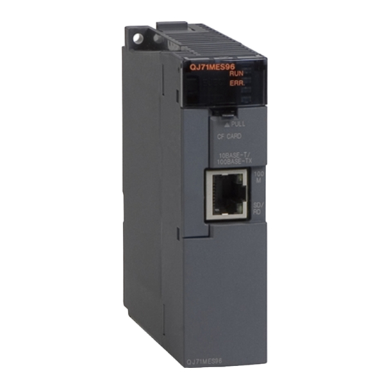
SYSTEM CONFIGURATION 2.5 Checking Function Version and Serial Number The serial No. and function version of the MES interface module can be confirmed on the rating plate and GX Developer's system monitor. (1) Confirming the serial number on the rating plate The rating plate is situated on the side face of the MES interface module. - Page 53 SYSTEM CONFIGURATION (2) Checking on the front of the module The serial No. and function version on the serial number display are also indicated on the front of the module (lower part). Function version 191021102450001-B Serial number Figure 2.9 "SERIAL" on the serial number display on the front of the MES interface module 2.5 Checking Function Version and Serial Number - 20...
- Page 54 SYSTEM CONFIGURATION (3) Confirming the serial number on the system monitor (Product Information List) To display the screen for checking the serial number and function version, select [Diagnostics] [System monitor] in GX Developer. Product inf. list Serial Function number version Figure 2.10 [Product Information List] of GX Developer Production number display Since the MES interface module does not support the production number display,...
-
Page 55: Precautions For System Configuration
SYSTEM CONFIGURATION 2.6 Precautions for System Configuration This section describes precautions for system configuration. 2.6.1 Precautions for using Redundant CPU The following describes the precautions for using the Redundant CPU. (1) Mountable base unit When using the MES interface module in a redundant system, be sure to mount the MES interface module to the extension base unit for CPU or redundant power supply. -
Page 56: Precautions For Using Multiple Cpu System
SYSTEM CONFIGURATION 2.6.2 Precautions for using multiple CPU system The following describes the precautions for using the multiple CPU system. (1) Access to each CPU module at start-up of multiple CPU system In the system in which a MES interface module is mounted in the multiple CPU system, an error may occur when accessing other CPU from the MES interface module or accessing the other station via a network module controlled by other CPU from the MES interface module due to the difference of start-up time of each CPU... -
Page 57: Precautions For Using Database
SYSTEM CONFIGURATION 2.6.4 Precautions for using database The following shows the precautions for using database. For characters that can be used for field and table names, refer to the following: Appendix 2.4 Characters available for field names, table names, stored procedure names,etc. - Page 58 SYSTEM CONFIGURATION (c) When MX MESInterface whose software version is "1.16S" or earlier is installed, use SQL Server with any of the following condition: • The owner of the database file created with SQL Server is an SQL Server authenticated user. •...
-
Page 59: Considerations For Performance/Specifications
SYSTEM CONFIGURATION 2.6.5 Considerations for performance/specifications (1) Startup time The time from when a CPU module is started to when the processing of MES interface function is ready for execution in an MES interface module varies depending on the system configuration and settings. The startup time can be lengthened depending on any of the following factors: •... -
Page 60: Chapter 3 Specifications 3 - 1 To
SPECIFICATIONS CHAPTER 3 SPECIFICATIONS This chapter explains the performance specifications, functions, buffer memory, etc. of the MES interface module and the MX MESInterface. For general specifications of the MES interface module, refer to the following manual. QCPU User's Manual (Hardware Design, Maintenance and Inspection) 3.1 Performance Specifications This section explains the MES interface module and the MX MESInterface performance specifications. - Page 61 SPECIFICATIONS (2) Software specifications Table 3.2 MX MESInterface performance specifications Reference Item Specifications section No. of connected databases Maximum 32 items/project ® • Oracle 8i (32bit) ® • Oracle 9i (32bit) ® • Oracle 10g (32bit) ® • Oracle 11g (32bit, 64bit) ®...
- Page 62 SPECIFICATIONS (From the previous page) Table 3.2 MX MESInterface performance specifications Reference Item Specifications section Maximum 2 programs/job Program Allowable number of One program before execution of initial action + one program after Section 7.10.3 execution settings execution of final action No.
- Page 63 SPECIFICATIONS Performance of the MES interface module and the system using the MES interface module differs depending on the following factors. Conduct a verification by user prior to starting the system. • Operating environment (personal computer, network, and the CompactFlash card) •...
- Page 64 SPECIFICATIONS 3.2 Accessible Devices and Ranges This section explains the accessible devices and ranges. For inaccessible CPU modules, refer to the following. Appendix 6 Data Collection Method for CPUs that cannot be Accessed Directly (1) Accessible CPU modules Table 3.3 Accessible CPU modules Model PLC series Basic model QCPU...
-
Page 65: Accessible Devices And Ranges
SPECIFICATIONS (2) Accessible routes (a) Single network MES interface Network module module Network 2 to 7 Request Relay Relay Network 1 Network 8 Access target CPU station station source Network communication route The network is any of CC IE Control, NET/10(H), Ethernet, or CC IE Field. The following lists CPU modules that can be used on the network communication route. - Page 66 SPECIFICATIONS Table 3.5 Single network Access target CPU (PLC series) Network communication QCPU (A mode), C Controller route LCPU QnACPU QCPU (Q mode) RCPU ACPU module CC-Link × × : Accessible ×: Inaccessible For the network No. and the station number, set the same values as that set in the parameter settings of the access target module.
- Page 67 SPECIFICATIONS (b) Different network MES interface Network module module Network 2 to 7 C24 multidrop CC-Link Request Relay Relay Relay Network 1 Access target CPU Network 8 source station station station Network communication route Co-existence network communication route The network is any of CC IE Control, NET/10(H), Ethernet, or CC IE Field. The following lists CPU modules that can be used on the network communication route and the communication routes of other network types.
- Page 68 SPECIFICATIONS Table 3.7 Different network Access target CPU (PLC series) Network Co-existence QCPU QCPU (A mode), C Controller communication route network route LCPU QnACPU RCPU ACPU module (Q mode) CC IE Control, × × × NET/10(H) CC-Link, C24 *1*9 × ×...
- Page 69 SPECIFICATIONS (3) Accessible devices Table 3.8 Accessible devices QCPU QCPU QnACP C Controller Device RCPU LCPU ACPU (Q mode) (A mode) module (Device name) Function input (FX) × × × × × × × Function output (FY) × × × ×...
- Page 70 SPECIFICATIONS QCPU QCPU QnACP C Controller RCPU Device LCPU ACPU (Q mode) (A mode) module (Device name) Cyclic transmission area × × × × *12 *15 Module access device (U3En\G) device Cyclic transmission area × × × × × × ×...
-
Page 71: Function List
SPECIFICATIONS 3.3 Function List This section lists the MES interface module functions. (1) Function summary The following explains the function summary of the MES interface module and MX MESInterface. The functions of the items are listed (2) and the subsequent descriptions. MX MESInterface Database Database... - Page 72 SPECIFICATIONS (2) MES interface module function list Table 3.9 MES interface module function list Reference Function Description section Section 6.1 DB interface function Executes access to the database in units of jobs. Section 7.10 Section 7.11 Collects device data of the programmable controller CPUs on the network in units of tags.
- Page 73 Execute a job as a one-shot task. Section 7.12.6 The product information of the MES Interface Function Configuration Tool and the Help Section 7.14 Connect to MITSUBISHI ELECTRIC FA Global Website screen can be displayed. 3.3 Function List - 14...
- Page 74 SPECIFICATIONS (4) DB Connection Service function list Table 3.11 DB Connection Service function list Reference Function Description section ODBC connection function Connects the MES interface module and the ODBC interface for database. Executes a program on the application server computer upon request from the MES Program execution function interface module.
-
Page 75: I/O Signals For Programmable Controller Cpu
SPECIFICATIONS 3.4 I/O Signals for Programmable Controller CPU 3.4.1 I/O signal list The following lists the MES interface module I/O signals to the programmable controller CPU. The following I/O signal assignment is based on the case where the start I/O No. of the MES interface module is "0000"... - Page 76 SPECIFICATIONS (From the previous page) Table 3.12 I/O signal list Signal direction MES interface module Signal direction programmable controller CPU Programmable controller CPU MES interface module Device Device Signal name Signal name ERR. LED status Error clear request ON: Lighting, flashing OFF: Extinction ON: Error clear request OFF: —...
-
Page 77: I/O Signals Details
SPECIFICATIONS 3.4.2 I/O signals details The following table shows the details of the I/O signals of the MES interface module. (1) Input signals details Table 3.13 Input signals details Device Signal name Description Turns ON when the MES interface module becomes ready after the programmable controller is Module READY powered ON from OFF or the programmable controller CPU is reset. - Page 78 SPECIFICATIONS (From the previous page) Table 3.13 Input signals details Device Signal name Description Turns ON when the MES interface function operation is enabled. This indicates that MES interface function processing is executable. Turns OFF when the MES interface function is in stop. The MES interface function processing stops in the following cases.
- Page 79 SPECIFICATIONS (From the previous page) Table 3.13 Input signals details Device Signal name Description Turns ON when an error occurs in communications with the access target CPU. Access target CPU When this device is ON, the error code is stored into the Access target CPU setting status area error (Buffer memory address: 4000 to 4071).
-
Page 80: Buffer Memory List
SPECIFICATIONS 3.5 Buffer Memory List The buffer memory list is shown below. Table 3.15 Buffer memory list Read/ Address Initial Reference Application Name (Decimal(Hex)) value section write RUN LED status 0: OFF 1: ON ERR. LED status 0: OFF 1: ON 2: Flash Switch 1 status (Mode setting) 0000h: Online 0001h: Hardware test... - Page 81 SPECIFICATIONS (From the previous page) Table 3.15 Buffer memory list Read/ Address Initial Reference Application Name (Decimal(Hex)) value section write Error code Current error Section System area — — area 3.6.4 142 to 145 Time to 91 146 to 149 Use prohibited System area —...
- Page 82 SPECIFICATIONS (From the previous page) Table 3.15 Buffer memory list Read/ Address Initial Reference Application Name (Decimal(Hex)) value section write 248 to 799 Use prohibited System area — — — to 31F 800 to 801 Sampling/ Current cycle (Unit: second) (320 to 321 Section...
- Page 83 SPECIFICATIONS (From the previous page) Table 3.15 Buffer memory list Read/ Address Initial Reference Application Name (Decimal(Hex)) value section write 4072 to 11499 (FE8 Use prohibited System area — — — 2CEB 11500 "Time synchronization" setting status (2CEC 0: [Synchronize with PLC CPU time]1: [Synchronize with SNTP] Section 11501 to 11507 3.6.10...
- Page 84 SPECIFICATIONS The following table shows the error code area assignment for the Access target CPUs 1 to 64 (Buffer memory address: 4008 to 4071). Table 3.17 Access target CPU 1 to 64, error code areas Access target CPU 1 to 64, error code areas Name Access target CPU 1 to 10, error codes 4008...
-
Page 85: Buffer Memory Details
SPECIFICATIONS 3.6 Buffer Memory Details This section explains the buffer memory details. (1) The values stored in buffer memory are cleared when the programmable controller is powered ON from OFF, or the programmable controller CPU is reset. (2) When a value of 65536 or more is stored in the area composed of one word, a count is stopped at FFFFh (65535). -
Page 86: Network Settings Status Area
SPECIFICATIONS (3) Storage example of Default gateway (Buffer memory address: 59 to 60) For 192. 168. 3. 254, each octet (192 (first octet). 168 (second octet). 3 (third octet). 254 (fourth octet)) is stored as follows: Buffer memory address: 59 (254) Third octet value Fourth octet value... -
Page 87: Current Error Area
SPECIFICATIONS 3.6.4 Current error area (1) Error code (Buffer memory address: 140) An error code which indicates the error contents is stored. For error codes, refer to the following: Section 10.2 Error Code List (2) Time (Buffer memory address: 142 to 145) The time when the error occurred is stored in BCD code. -
Page 88: Error Log Area
SPECIFICATIONS 3.6.5 Error log area (1) Error count (Buffer memory address: 150) (a) The cumulative number of registrations to the Error log area is stored. (2) Error log write pointer (Buffer memory address: 151) (a) The number of error log to which the latest error is registered is stored. 0: No error (No error log stored) 1 or more: Error log number of the latest error stored The pointer value of "16"... - Page 89 SPECIFICATIONS (1) The information of the Error log area can be confirmed on the following diagnostic screen. Select [System monitor] [Error Display] of GX Developer (Section 10.1.3 System monitor) (2) The Error log area can be cleared in either of the following methods. (a) Power ON the programmable controller from OFF or reset the programmable controller CPU.
-
Page 90: Sampling/Monitoring Cycle Area
SPECIFICATIONS 3.6.6 Sampling/monitoring cycle area The MES interface module monitors the device data sampling time and trigger conditions alternately. The time (cycle) required for this repetition can be confirmed in this area. When the sampling/monitoring cycle is one second, device tag sampling and trigger conditions are monitored based on the set values. - Page 91 SPECIFICATIONS (3) Sampling error information (Buffer memory address: 1008 to 1011) (a) The tag sampling error information is stored. (b) The bit corresponding to the tag setting No. to which the Sampling error occurred is turned ON. 0: No sampling error 1: Sampling error detected b10 b9 b8 b7...
-
Page 92: Current Tag Data Value Area
SPECIFICATIONS 3.6.8 Current tag data value area The specified current tag data is stored. This section explains how to display the specified tag data in the Current tag data value area. Set the tag number displayed in the No. of requested tag (Buffer memory address: 1290). - Page 93 SPECIFICATIONS (3) Update count (Buffer memory address: 1292) (a) After the power is ON, the cumulative number of updates for the Current tag data value (Buffer memory address: 1300 to 1811) is stored. (b) After specifying the tag number displayed as the No. of requested tag (Buffer memory address: 1290), when the update count is increased, the Current tag data value (Buffer memory address: 1300 to 1811) is updated with the value of the specified tag number.
- Page 94 SPECIFICATIONS (5) Current tag data value (Buffer memory address: 1300 to 1811) (a) The current values of the tag components whose No. is specified with the No. of requested tag (Buffer memory address: 1290) are stored. (b) Two words are assigned per tag component. 1300 Current value of 1301...
-
Page 95: Access Target Cpu Setting Status Area
SPECIFICATIONS 3.6.9 Access target CPU setting status area (1) Access target CPU setting information (Buffer memory address: 4000 to 4003) (a) The information on whether [Access target CPU settings] have been made or not is stored. (b) The bit corresponding to the preset Access target CPU setting No. is turned ON. 0: Not set 1: Set b10 b9... -
Page 96: Information Linkage Function Area
SPECIFICATIONS 3.6.10 Information linkage function area (1) "Time synchronization" setting status (Buffer memory address: 11500) (a) The setting status of [Time synchronization setting] is stored. For [Time synchronization setting], refer to the following. Section 7.6.2 Setting items in Time synchronization setting 0: [Synchronize with PLC CPU time] 1: [Synchronize with SNTP] (b) When selecting [Synchronize with SNTP] in [Time synchronization setting]... - Page 97 SPECIFICATIONS (4) No. of trigger buffer data (Buffer memory address: 11511) The number of times the current trigger buffer has been used is stored. If the number of times the trigger buffer has been used is always large, check the number of jobs for which [Trigger buffering] is enabled and the trigger condition setting.
-
Page 98: Chapter 4 Settings And Procedure To Operation 4 - 1 To
SETTINGS AND PROCEDURE TO OPERATION CHAPTER 4 SETTINGS AND PROCEDURE TO OPERATION This chapter explains the settings and procedure to operate the MES interface module in a system. (1) Before use, make sure to read SAFETY PRECAUTIONS at the beginning of this manual. - Page 99 SETTINGS AND PROCEDURE TO OPERATION 4.2 Settings and Procedure to Operation This section explains the schematic procedure up to operation for using the MES interface function. (1) Starting the server computer Start the server computer, and then the MES interface module. (2) Starting the MES interface module Procedure to operation Server computer/SNTP server computer...
- Page 100 SETTINGS AND PROCEDURE TO OPERATION (2) Starting the MES interface module Start the server computer, and then the MES interface module. (1) Starting the server computer in this section Procedure to operation MES interface module Configuration computer Install MES Interface Function Configuration Tool. Section 5.1 Installation Mount a battery to the QJ71MES96 MES interface module.
- Page 101 SETTINGS AND PROCEDURE TO OPERATION (From the previous page) (From the previous page) Set the target MES interface module. Write a project to the MES interface module. • Section 7.12.1 Setting the target MES interface module • Section 7.12.2 Writing the MES interface function settings MES interface module Configuration computer...
- Page 102 SETTINGS AND PROCEDURE TO OPERATION As necessary, execute the self-diagnostic test for checking the communication function and hardware of the MES interface module. Section 4.6 Self-diagnostics Test For a battery, refer to the following: Section 4.8 Battery Section 4.9 Operation without Mounting Battery Section 4.10 Removing Battery for Storage If an account is forgotten and therefore connection to the MES interface module cannot be made, eject the CompactFlash card from the MES interface module, then follow the procedure in the...
-
Page 103: Parts Names
SETTINGS AND PROCEDURE TO OPERATION 4.3 Parts Names This section explains the parts names of the MES interface module. (1) With the LED cover closed Figure 4.3 With the LED cover closed (2) With the LED cover open Figure 4.4 With the LED cover open 4.3 Parts Names... - Page 104 SETTINGS AND PROCEDURE TO OPERATION Table 4.2 Parts names Name Description 1) Indicator LED Refer to (3) Indicator LED display contents. Used for connecting a MES interface module to the following personal computers: • Configuration computer 10BASE-T/100BASE-TX • Server computer interface connector (RJ45) •...
-
Page 105: Wiring
SETTINGS AND PROCEDURE TO OPERATION 4.4 Wiring 4.4.1 Wiring This section explains how to connect cables to the MES interface module. MES interface module QJ71MES96N ERR. PULL CF CARD 10BASE-T/ 100BASE-TX Intranet Twisted pair cable (Straight) QJ71MES96N Figure 4.6 Wiring Remark For the equipment required for 10BASE-T/100BASE-TX connection and system configuration examples, refer to the following. -
Page 106: Intelligent Function Module Switch Settings
SETTINGS AND PROCEDURE TO OPERATION 4.5 Intelligent Function Module Switch Settings The intelligent function module switches are used to make the mode setting, default operation setting, battery error detection setting, and response monitoring time setting. Select [Project] window [Parameter] [PLC parameter] [I/O assignment] tab of GX Developer. - Page 107 SETTINGS AND PROCEDURE TO OPERATION Table 4.5 Setting items of the [Switch setting for I/O and intelligent function module] dialog box Switch number Description Switch 1 Mode setting Switch 2 Default operation setting/battery error detection setting Switch 3 (Lower byte) Response monitoring time setting Switch 4 to 5 For system use (Do not set.)
- Page 108 SETTINGS AND PROCEDURE TO OPERATION Use the default operation setting when changing the settings of the MES interface module connected to the configuration computer on a 1:1 basis. (b) Battery error detection setting (bit 2) Set whether to detect battery errors while the QJ71MES96 MES interface module is operating without battery.
-
Page 109: Self-Diagnostics Test
SETTINGS AND PROCEDURE TO OPERATION 4.6 Self-diagnostics Test This section explains the self-diagnostics test designed for checking the MES interface module communication function and hardware. 4.6.1 Self-loopback test Execute the self-loopback test for a hardware check including the communication function of the MES interface module (10BASE-T/100BASE-TX interface). -
Page 110: Hardware Test
SETTINGS AND PROCEDURE TO OPERATION 4.6.2 Hardware test Test ROM/RAM/intelligent function module switch settings for the MES interface module. (1) MES interface module operation mode setting In [Switch setting for I/O and intelligent function module] of GX Developer, set "Mode setting" to "Hardware test". (Switch 1: 0001h) Match the other intelligent function module switch settings to the setting contents used. -
Page 111: Compactflash Card
SETTINGS AND PROCEDURE TO OPERATION 4.7 CompactFlash Card 4.7.1 Precautions for using a CompactFlash card This section explains the precautions for using the CompactFlash card. (1) Available CompactFlash cards Use a CompactFlash card listed in Section 2.3. ( Section 2.3 Connection System Equipment) Failure to do so may cause a problem such as data corruption in the CompactFlash card and system stop. -
Page 112: Installation/Removing The Compactflash Card
SETTINGS AND PROCEDURE TO OPERATION ® (b) Do not format the CompactFlash card with Windows If doing so by mistake, restore the card according to the CompactFlash card manual. (6) About a CompactFlash card file User-original files cannot be stored to the CompactFlash card installed to the MES interface module. - Page 113 SETTINGS AND PROCEDURE TO OPERATION (Removal or replacement of the CompactFlash card) Before removing or replacing the CompactFlash card, be sure to stop file access by the following procedure. Removal/replacement of a CompactFlash card Is the programmable Power ON the programmable controller. controller power ON? Disable the read from/write to the CompactFlash card by file access stop processing.
- Page 114 SETTINGS AND PROCEDURE TO OPERATION (1) Stopping file access Stop file access. • Turn the File access stop request (Y2) ON from OFF. Check the file access stop by the following: • Check the CompactFlash card status (X1) is OFF. •...
- Page 115 SETTINGS AND PROCEDURE TO OPERATION Install the CompactFlash card. When installing the CompactFlash card into the MES interface module, pay attention to the orientation of the card. Push the CompactFlash card securely into the slot until it is flush with the EJECT button.
- Page 116 SETTINGS AND PROCEDURE TO OPERATION (3) Removing a CompactFlash card Open the LED cover on the front of the MES interface module, then remove the CompactFlash card. LED cover EJECT button EJECT button Press Remove in this PULL CF CARD direction.
-
Page 117: Battery
SETTINGS AND PROCEDURE TO OPERATION 4.8 Battery This section explains the mounting and replacement of the battery. 4.8.1 Battery specifications This section shows the specifications of the QJ71MES96 MES interface module battery. Table 4.9 Battery specifications Description Item Q6BAT Type Manganese dioxide lithium primary battery Initial voltage 3.0 V... -
Page 118: Battery Replacement
SETTINGS AND PROCEDURE TO OPERATION 4.8.3 Battery replacement This section explains how to replace the QJ71MES96 MES interface module battery. The battery is used for file protection. If the voltage of the battery has dropped, the battery must be replaced. (1) Checking the module for a battery voltage drop Check for a battery voltage drop in the Battery status area (Buffer memory address: 7). - Page 119 SETTINGS AND PROCEDURE TO OPERATION (2) Battery (Q6BAT) life (a) The following shows the service life of the QJ71MES96 MES interface module battery. Table 4.10 Battery life Battery life Power-on time Actual service value Guaranteed time after battery Guaranteed value ratio (Reference value) error...
- Page 120 SETTINGS AND PROCEDURE TO OPERATION (3) Battery replacement procedure When the life of the battery comes to an end, replace the battery, following the procedure below. The programmable controller must be powered ON for 10 minutes or more before removing the battery. The module holds the data on the memory for three minutes (backup power time) by the capacitor even after the battery is removed.
-
Page 121: Operation Without Mounting Battery
SETTINGS AND PROCEDURE TO OPERATION 4.9 Operation without Mounting Battery This section explains operation without mounting a battery to the MES interface module. (1) Shutdown operation required when the programmable controller is powered Make sure to perform shutdown operation when the programmable controller is powered OFF regardless of whether the battery is mounted or not. -
Page 122: Removing Battery For Storage
SETTINGS AND PROCEDURE TO OPERATION 4.10 Removing Battery for Storage When storing the QJ71MES96 MES interface module without mounting a battery, make sure to perform the shutdown operation, then power OFF the programmable controller and remove the battery. Not doing so may cause the data corruption in the CompactFlash card being accessed or a file system error. -
Page 123: Installation And Uninstallation
INSTALLATION AND UNINSTALLATION CHAPTER 5 INSTALLATION AND UNINSTALLATION This chapter explains how to install the execution software of MX MESInterface to each operating environment and how to uninstall it. 5.1 Installation This section explains how to install MX MESInterface. (1) MX MESInterface installation procedure Installation start Execute setup.exe.*1 Select the component to be... - Page 124 INSTALLATION AND UNINSTALLATION (2) MX MESInterface installation For system configurations, refer to the following: Section 2.1.2 System configuration for installation (1) Before installing MX MESInterface, close any other applications running on ® Windows (2) The installer may not work normally because the update program of operating ®...
- Page 125 INSTALLATION AND UNINSTALLATION ® ® (The following screens are for Microsoft Windows 7 Professional Operating System.) (Start) Start Windows Explorer, then click the drive in which the CD-ROM is loaded. Double click "setup.exe". To display Windows Explorer, right click [Start], then select [Explore].
- Page 126 INSTALLATION AND UNINSTALLATION (From the previous page) The dialog box for selecting the component to be installed is displayed. Select the component to be installed with the radio button, then click the Install button. The procedures up to step 8 are common for each tool.
- Page 127 INSTALLATION AND UNINSTALLATION (From the previous page) The left screen appears. Check that all applications have been closed, then click the button. If any applications are running, close them all. Setup starts. The left screen appears. Check the description, then click the button.
-
Page 128
INSTALLATION AND UNINSTALLATION (From the previous page) The installation confirmation screen is displayed. To install it, click the Install button. If you want to review any of your installation
- Page 129 INSTALLATION AND UNINSTALLATION (From the previous page) When installing MES Interface Function Configuration Tool, the screen shown on the left is displayed. To associate the extension (.mup) of a project file with a program, click the button. When the left screen appears, installation is complete.
- Page 130 INSTALLATION AND UNINSTALLATION After installing MES Interface Function Configuration Tool and DB Connection Service Setting Tool, the following icons are registered. Figure 5.2 Icon registration ® For Windows Vista or later, "DB Connection Service Client" is installed, and its icon (DBCnctClient) is shown in the list appeared by clicking [Startup].
Page 131: Uninstallation
INSTALLATION AND UNINSTALLATION 5.2 Uninstallation This section explains how to uninstall MX MESInterface. (1) MES Interface Function Configuration Tool, DB Connection Service, and DB Connection Service Setting Tool ® ® (The following screens are for Microsoft Windows 7 Professional Operating System.) (Start) From the Control Panel, select [Add or Remove...- Page 132 INSTALLATION AND UNINSTALLATION (From the previous page) Select the program to be deleted and click the button. Change/Remove For DB Connection Service and Setting Tool DB connection service and setting tool For MES Interface Function Configuration Tool MELSEC-Q series MES interface function configuration tool (MX MESInterface) *1 When the software (version 1.15R or earlier) is installed, [DB connection service and setting tool...
- Page 133 INSTALLATION AND UNINSTALLATION (From the previous page) Confirm the file to be deleted. To uninstall it, click the button. To not uninstall it, click the button. Clicking the button returns to the previous screen. component indicates the installed icons • The and file If the left screen appears, click the No to All...
Page 134: Chapter 6 Functions 6 - 1 To
FUNCTIONS CHAPTER 6 FUNCTIONS This chapter explains the MES interface functions of the MES interface module. The MES interface functions are set using MES Interface Function Configuration Tool. Chapter 7 MES INTERFACE FUNCTION CONFIGURATION TOOL 6.1 DB Interface Function The DB interface function executes access to the database in units of jobs. 6.1.1 DB interface function operation The operation of the DB interface function is shown below.Page 135: Job Execution Procedure
FUNCTIONS 6.1.2 Job execution procedure The following shows the job execution procedure. Start Stopped Is the MES interface function working? No job is executed while the function is stopped. Activate the MES interface function. Working • Section 7.13.1 Checking the operation status of the MES interface function •...Page 136: Sections 2
FUNCTIONS (From the previous page) Executed in order Actions are executed. Up to 10 actions can set for a job, and they are executed in order. • Section 6.1.6 SQL text transmission (Communication action) • Section 6.1.7 Stored procedure call function (Communication action) •...Page 137: Tag Function
FUNCTIONS 6.1.3 Tag function The tag function collects device data of the programmable controller CPUs on the network in units of tags. By allocating database fields to tag components, the DB interface function enables the following. • Database value reading/writing •...Page 138: Trigger Monitoring Function
FUNCTIONS 6.1.4 Trigger monitoring function The trigger monitoring function monitors values such as the time and tag values and, when the trigger condition changes from false to true (when the condition is met), starts a job. The following setting options are available as conditions for start. •...- Page 139 FUNCTIONS (1) The job can be started only when the device tags used for trigger conditions of all jobs have been sampled normally. *1 When the first five digits of the serial No. is "11011" or earlier, the operation of the MES interface module is different.
Page 140: Trigger Buffering Function
FUNCTIONS 6.1.5 Trigger buffering function When multiple sets of trigger conditions (conditions for data transmission) are met in a concentrated manner, their data and trigger times are buffered in the module's internal memory so that actions (data operation/transmission) can be executed later using the buffered data.- Page 141 FUNCTIONS (b) In the case of load concentration (Trigger interval Processing time for action) • Every time a trigger condition is met, tag data and trigger time are stored in the trigger buffer. • When action processing is not completed in time, up to 128 pieces of trigger information are stored in the buffer.
- Page 142 FUNCTIONS (1) For job operations performed when [Trigger buffering] is disabled, refer to the following: Section 6.1.11 (1) Operation behavior of jobs (2) Whether a trigger condition changed from false to true or not is determined at the time of sampling. Section 7.10.2 (6) Value monitoring startup (3) When the trigger condition of the job, for which the DB buffering function is disabled, is satisfied in the state where a communication error occurs...
Page 143: Sql Text Transmission (Communication Action)
FUNCTIONS 6.1.6 SQL text transmission (Communication action) The SQL text transmission function allows automatic creation of SQL texts, enabling communications with the database. The following commands can be selected for the SQL text. • Select/MultiSelect • Update • Insert • Delete For the SQL text transmission setting, refer to the following: Section 7.11.1 Setting items in Communication action Database server computer...Page 144: Stored Procedure Call Function (Communication Action)
FUNCTIONS 6.1.7 Stored procedure call function (Communication action) The stored procedure call function starts up a stored procedure in the database. By executing a stored procedure in the database, the variety and complex control can be performed for the data in the database. For the stored procedure call function settings, refer to the following: Section 7.11.3 Setting items in Communication action (Stored procedure) The stored procedure call function is used to pass/receive the values to/from the stored...- Page 145 FUNCTIONS (e) Acquiring output arguments or I/O arguments When the following procedures are called in the stored procedure of SQL Server, the MES interface module cannot receive the value assigned to the argument as a execution result of the stored procedure. •...
Page 146: Arithmetic Processing Function (Operation Action)
FUNCTIONS 6.1.8 Arithmetic processing function (Operation action) The arithmetic processing function performs operations for tag component values. In this function, up to 20 dyadic operations can be processed per operation action. By storing an operation result in the temporary variable area, complicated operations are also executable.Page 147: Db Buffering Function
FUNCTIONS 6.1.10 DB buffering function (1) DB buffering function The DB buffering function temporarily stores SQL texts or stored procedure call information into a CompactFlash card when they cannot be sent due to network disconnection or failure of the database server computer. After recovery, the buffered SQL texts or stored procedure call information are automatically sent to the database.- Page 148 FUNCTIONS (2) Factors for starting DB buffering DB buffering is conducted when SQL texts or stored procedure call information cannot be sent to the database by any of the following causes, (a) or (b). (a) Disconnection on the network, or failure of the database server computer Upon detection of a connection timeout, DB buffering is started.
- Page 149 FUNCTIONS (4) Setting the DB buffering (a) Setting for DB buffering function Set the tag components or CompactFlash card capacity for DB buffering function. For the setting methods, refer to the following: Section 7.6.4 Setting items in DB buffering setting (b) Enabling the DB buffering function Set whether to enable the DB buffering function for each job.
- Page 150 FUNCTIONS (6) Clearing the DB buffer The DB buffer is cleared by the following: (a) After writing the MES interface function setting to the MES interface module, performing any of the following operations • Perform [Update settings] • Power OFF and then ON •...
- Page 151 FUNCTIONS (7) DB buffering operation The job data whose trigger condition has been met is processed as shown below depending on the status of communication or DB buffering settings. Table 6.4 DB buffering operation Communication Data of DB buffering setting Operation status DB buffer...
- Page 152 FUNCTIONS (8) Operation while data is being stored to DB buffer The job processing which is started up while the data is being stored differs depending on the operation settings of resend buffer selected on each job. Related settings • Setting of each job ( Section 7.10.4) •...
- Page 153 FUNCTIONS (b) When "Adding to the buffered data" is selected The following shows the job processing when "Adding to the buffered data" is selected. Processing content When the data cannot be sent to the database, it is stored to DB buffer after the detection of a timeout.
Page 154: Precautions
FUNCTIONS 6.1.11 Precautions (1) Operation behavior of jobs (a) When a trigger condition for a job is met again during execution of the job 1) When [Trigger buffering] is disabled for the job Because the job is being executed, it is not executed again. Condition value Tag component value Sampling...- Page 155 FUNCTIONS (2) When an error occurs in job execution (a) The job execution is canceled when the error cause is the following: • Failure in device data writing due to network disconnection within the programmable controller system • Failure in device data writing, or an operation error •...
Page 156: Xml Processing Function
FUNCTIONS 6.2 XML Processing Function The XML processing function is a function by which execution of XML format message requests from user applications can be processed. The XML processing function allows the following instructions for job execution. • One-shot execution of a job •...Page 157: Time Synchronization Function
FUNCTIONS 6.3 Time Synchronization Function The time synchronization function adjusts the time of the MES interface module to be synchronized with the time of the SNTP server computer or a programmable controller CPU (No.1 CPU in the multiple CPU system) on the network. Time information is utilized for job start conditions or in send data to the database.Page 158: Daylight Saving Time Function
FUNCTIONS 6.3.2 Daylight saving time function The daylight saving time function allows the time of the MES interface module to be changed to the daylight saving time during the period of summer time, using the clock time of the SNTP server computer. For the daylight saving time setting, refer to the following.Page 159: Mes Interface Function Configuration Tool
MES INTERFACE FUNCTION CONFIGURATION TOOL CHAPTER 7 MES INTERFACE FUNCTION CONFIGURATION TOOL This chapter explains the MES Interface Function Configuration Tool. 7.1 MES Interface Function Configuration Tool The MES Interface Function Configuration Tool is used to configure various settings required for the MES interface function in the MES interface module. In addition to the configuration, the MES interface function offers features such as the operation status check, working log check, or stop/restart operation.Page 160: Screen Structure
MES INTERFACE FUNCTION CONFIGURATION TOOL 7.3 Screen Structure This section explains the screen structure of the MES Interface Function Configuration Tool. 7.3.1 Screen structure Toolbar Menu Section 7.3.3 Section 7.3.2 Menu Toolbar configuration configuration Edit items tree Section 7.3.4 Operations using the Edit items tree Detailed setting edit screen...Page 161: Screen Structure
MES INTERFACE FUNCTION CONFIGURATION TOOL Remark When a text takes up too much space and all characters are not displayed, per- form the following: • Resize the column of the table. Drag the right border of the column to the desired width. Figure 7.2 Before resizing the column Figure 7.3 Table column width adjustment •...Page 162: Menu Configuration
MES INTERFACE FUNCTION CONFIGURATION TOOL 7.3.2 Menu configuration This section shows each command provided on the menu bar. (1) Project Figure 7.5 Project menu Table 7.1 Project menu items Reference Item Description section Creates a new project. Section 7.4.1 Open Retrieves an existing project.- Page 163 MES INTERFACE FUNCTION CONFIGURATION TOOL (3) View Figure 7.7 View menu Table 7.3 View menu items Reference Item Description section Toolbar Select whether to show or hide the toolbar. — Status bar Select whether to show or hide the status bar. (4) Online Figure 7.8 Online menu Table 7.4 Online menu items...
Page 164: Toolbar Configuration
Displays the product information of the MES Interface Function Configuration Product information Tool. Section 7.14 Connect to MITSUBISHI Displays the [Connect to MITSUBISHI ELECTRIC FA Global Website] screen. ELECTRIC FA Global Website 7.3.3 Toolbar configuration This section shows each command provided on the toolbar. Figure 7.10 Toolbar Table 7.6 Toolbar items...Page 165: Operations Using The Edit Items Tree
MES INTERFACE FUNCTION CONFIGURATION TOOL 7.3.4 Operations using the Edit items tree The Edit items tree shows overall project settings in a tree. This section explains the operations using the Edit items tree. Project root Item Setting type Figure 7.11 Edit items tree (1) Selecting an item When double-clicking the project root or each setting type, some items are displayed.- Page 166 MES INTERFACE FUNCTION CONFIGURATION TOOL (3) Deleting an item Selecting an item to be deleted and performing either of the following will delete the item. • Click (Delete item). • Select [Edit] [Delete item] from the menu. (1) When the selected item is currently used for another item, it cannot be deleted. As the error dialog box appears, identify the location, stop using it for another item, and then delete the item.
Page 167: Project File Handling
MES INTERFACE FUNCTION CONFIGURATION TOOL 7.4 Project File Handling This section explains how to handle project files. MES Interface Function Configuration Tool treats the MES interface function settings for a single MES interface module as one project. 7.4.1 Creating a new project Create a new project.Page 168: Saving A Project
MES INTERFACE FUNCTION CONFIGURATION TOOL 7.4.3 Saving a project Save a project. (1) Save the current project. Perform either of the following: • Click (Save). • Select [Project] [Save] from the menu. (2) Saving a project under a new name Select [Project] [Save As] from the menu.Page 169: Importing A Project
MES INTERFACE FUNCTION CONFIGURATION TOOL 7.4.4 Importing a project Import an existing project. Any setting can be selected from an existing project and can be imported into the current project setting. This function is useful when settings of an existing project is utilized for another project. Select [Project] [Import] [Project file] from the menu.- Page 170 MES INTERFACE FUNCTION CONFIGURATION TOOL (1) Selecting an item to be imported In the tree, select the item to be imported. Table 7.10 Item to be imported Checked item Item to be imported Project root All items in the project All items under the setting type whose checkbox is checked Setting type Item...
Page 171: Importing A Csv File
MES INTERFACE FUNCTION CONFIGURATION TOOL 7.4.5 Importing a CSV file Import an existing CSV file. Any setting can be selected from a CSV file edited on a personal computer, and it can be imported into the setting of the current project. [System setting], [Access target CPU settings] and [Device tag settings] can be imported.- Page 172 MES INTERFACE FUNCTION CONFIGURATION TOOL When the CSV file to be imported is selected, the [Import from CSV files] dialog box is displayed. Make the setting referring to the following descriptions. Import After completing the setting, clicking the button starts the import. Existing registration information Project root...
- Page 173 MES INTERFACE FUNCTION CONFIGURATION TOOL (1) Selecting an item to be imported In the tree, select the item to be imported. Table 7.16 Item to be imported Checked item Item to be imported Project root All items in the project All items under the setting type whose checkbox is checked Setting type Item...
Page 174: Exporting A Csv File
MES INTERFACE FUNCTION CONFIGURATION TOOL 7.4.6 Exporting a CSV file Export the current project settings to a CSV file. Exported CSV files can be utilized for creating setting sheets or printing. [System setting], [Access target CPU settings], [Device tag settings], [Server service settings], and [Job settings] can be exported.Page 175: Project Setting
MES INTERFACE FUNCTION CONFIGURATION TOOL 7.5 Project Setting Set the information on the project (project name, comments). Click the project root in the Edit items tree. The "project setting" area is displayed on the detailed setting edit screen. Set the following items. Figure 7.18 [Project setting] Table 7.20 Setting items in [Project setting] Item...Page 176: System Setting
MES INTERFACE FUNCTION CONFIGURATION TOOL 7.6 System Setting Configure the initial settings for the MES interface module. Click [System setting] in the Edit items tree. The "system setting" area is displayed on the detailed setting edit screen. Make the setting referring to the following descriptions. Figure 7.19 [System setting] Table 7.21 Setting items in [System setting] Item...Page 177: Setting Items In Network Setting
MES INTERFACE FUNCTION CONFIGURATION TOOL 7.6.1 Setting items in Network setting Configure the settings necessary for connecting the MES interface module to the network. Figure 7.20 [Network settings] Table 7.22 Setting items in [Network settings] Item Description Set the IP address of the MES interface module in decimal notation. IP address (required) (Default: 192.168.3.3) Set the subnet mask in decimal notation.Page 178: Setting Items In Time Synchronization Setting
MES INTERFACE FUNCTION CONFIGURATION TOOL 7.6.2 Setting items in Time synchronization setting Make the time setting for the MES interface module. The time used in the MES interface module is obtained from the SNTP server computer or programmable controller CPU (CPU No.1 in the case of a multiple CPU system). To synchronize the time between the MES interface module and other devices on the network, using the time on the SNTP server computer is recommended.- Page 179 MES INTERFACE FUNCTION CONFIGURATION TOOL (c) Daylight saving setting Setting A click on the button displays the [Daylight saving setting] dialog box. Make settings for the following items, and click the button. Figure 7.22 [Daylight saving setting] Table 7.24 Setting items in [Daylight saving setting] Item Description Enable daylight saving...
- Page 180 MES INTERFACE FUNCTION CONFIGURATION TOOL (3) When time information is not obtainable from the SNTP server computer When the MES interface module cannot obtain time information from the SNTP server computer due to failure of the network or time synchronization server, it behaves as follows: (a) When time information is not obtained at the time of powering ON the programmable controller from OFF, or resetting the programmable controller CPU...
- Page 181 MES INTERFACE FUNCTION CONFIGURATION TOOL (4) Precautions on the time synchronization function (a) Synchronizing time with SNTP server computer 1) When [Synchronize with SNTP] is selected, an SNTP server computer is required. Note that the SNTP server computer must have the time synchronization server function.
Page 182: Setting Items In Account Setting
MES INTERFACE FUNCTION CONFIGURATION TOOL 7.6.3 Setting items in Account setting Set user authentication accounts used for access to the MES interface module. At least one account setting is required, and up to 16 accounts can be set. Figure 7.23 [Account setting] (1) Adding an account Clicking the button displays the [Add Account] dialog box.- Page 183 MES INTERFACE FUNCTION CONFIGURATION TOOL (2) Modifying an account Edit Selecting an account and clicking the button displays the [Edit Account] dialog box. Set the following items and click the button. Figure 7.25 [Edit Account] dialog box Table 7.26 Setting items in the [Edit Account] dialog box Item Description Enter a user name.
- Page 184 MES INTERFACE FUNCTION CONFIGURATION TOOL (4) Precautions on security of the MES interface module Although the MES interface module supports the basic authentication (account setting) using user names and passwords, it shall not completely protect the system from illegal access. When the programmable controller system security needs to be protected against illegal access, take measures at the user's discretion.
Page 185: Setting Items In Db Buffering Setting
MES INTERFACE FUNCTION CONFIGURATION TOOL 7.6.4 Setting items in DB buffering setting Configure the settings for the DB buffering function. For the DB buffering function setting, refer to the following: Section 6.1.10 DB buffering function Figure 7.26 [DB buffering settings] (1) DB buffering status (a) Select a tag component into which whether data are currently accumulated in the DB buffer or not is stored.- Page 186 MES INTERFACE FUNCTION CONFIGURATION TOOL (3) Resend DB buffer request (a) Select a tag component used to request for resend processing of the DB buffer. Note that the following tags are not selectable. • Tags for which [Prohibit data writing] is enabled •...
- Page 187 MES INTERFACE FUNCTION CONFIGURATION TOOL (4) Clear DB buffer request (a) Select a tag component used to request for clear processing of the DB buffer. Note that the following tags are not selectable. • Tags for which [Prohibit data writing] is enabled •...
- Page 188 MES INTERFACE FUNCTION CONFIGURATION TOOL (5) DB buffering full (a) Select a tag component into whose device the status of whether the DB buffer (Automatically resend buffer or Manually resend buffer) is full or not is stored. Note that the following tags are not selectable. •...
- Page 189 MES INTERFACE FUNCTION CONFIGURATION TOOL (7) DB buffering capacity (Range: 16MB to 512MB, Default: 64MB) (a) Set the capacity used for DB buffering out of the entire CompactFlash card capacity within the following range. Maximum capacity CompactFlash card capacity - 32M bytes Note that a sufficient free space is needed for the CompactFlash card.
- Page 190 MES INTERFACE FUNCTION CONFIGURATION TOOL (8) Operation of recovery from network disconnection Set the operation when the trigger conditions are met in case the data exists in the resend buffer. (a) Automatically resend buffer Select the buffering operation for when the communication is recovered from the communication disconnection in case the data are accumulated in the Automatically resend buffer of the DB buffer.
Page 191: Access Target Cpu Setting
MES INTERFACE FUNCTION CONFIGURATION TOOL 7.7 Access Target CPU Setting Set a connection channel to the access target CPU. The set CPU name is used in [Device tag settings]. Double-clicking [Access target CPU settings] in the Edit items tree displays relevant items.Page 192: Setting Items In Access Target Cpu Setting
MES INTERFACE FUNCTION CONFIGURATION TOOL 7.7.1 Setting items in Access target CPU setting Up to 64 items can be set in [Access target CPU settings] within one project. By default, a control CPU is set as the first item with "ControlCPU" displayed for CPU name.- Page 193 MES INTERFACE FUNCTION CONFIGURATION TOOL (2) PLC series (QCPU (Q mode)/RCPU, QCPU (A mode), LCPU, QnACPU, ACPU) Select the PLC series of the access target CPU. Select the QCPU (Q mode)/RCPU when accessing a C Controller module. (3) Multiple CPU specification (No specification, No.1 to No.4) Select a CPU No.
- Page 194 MES INTERFACE FUNCTION CONFIGURATION TOOL (c) Other station (Different network) To access a CPU module on another station over two types of networks 1) and 2) listed in Table 7.34, specify a different network. Table 7.36 Network types Network name CC-Link CC-Link IE Controller Network MELSECNET/10...
- Page 195 MES INTERFACE FUNCTION CONFIGURATION TOOL (6) Precautions on [Access target CPU settings] (a) The MES interface module prepares for communication with the access target CPU when executing [Update settings], powering ON the system from OFF, or resetting the programmable controller CPU. Therefore, if a large number of access target CPUs are set, several minutes are required for the preparation.
Page 196: Device Tag Setting
MES INTERFACE FUNCTION CONFIGURATION TOOL 7.8 Device Tag Setting Configure the settings for the tag function. For the tag function, refer to the following: Section 6.1.3 Tag function Configured tags are used in [Job settings], etc. Double-clicking [Device tag settings] in the Edit items tree displays relevant items. Selecting one of the items displays the corresponding edit screen on the detailed setting edit screen area.Page 197: Setting Items In Device Tag Setting
MES INTERFACE FUNCTION CONFIGURATION TOOL 7.8.1 Setting items in Device Tag setting Up to 64 items can be set in [Device tag settings] within one project. Figure 7.30 [Device tag settings] Table 7.37 Setting items in [Device tag settings] Item Description Device tag name Enter a device tag name.- Page 198 MES INTERFACE FUNCTION CONFIGURATION TOOL (1) Device tag name (Up to 16 characters) Enter a device tag name. Configured tags are used in [Job settings], etc. For characters that can be used for device tag names, refer to the following: Appendix 2.2 Characters that can be used for item names, component names, variable names, etc.
- Page 199 MES INTERFACE FUNCTION CONFIGURATION TOOL (c) Do not sample The tag is not sampled. (1) Select [Do not sample] in the cases shown below. This setting can reduce the load of the MES interface module. • Tags for which [Array setting] is set •...
- Page 200 MES INTERFACE FUNCTION CONFIGURATION TOOL Remark (1) Creating a user-specified system area The following explains how to create a user-specified system area in the program memory of the control CPU. Select [Online] [Format PLC memory] from the menu of GX Developer. As the [Format PLC memory] dialog box appears, select [Create a user setting area] in [Format Type].
Page 201: Setting Items In Array Setting
MES INTERFACE FUNCTION CONFIGURATION TOOL 7.8.2 Setting items in Array setting An array is a data format, in which the specified number of data of the same data type are arranged sequentially. The Array setting is set when writing multiple records extracted from a database to the same tag component.- Page 202 MES INTERFACE FUNCTION CONFIGURATION TOOL (b) Block Devices of all tag components are arranged as a block. The size of the block can be changed in [array block size]. For [array block size], refer to the following. Section 7.8.3 Setting items in Component setting Usually, the block size need not be changed because it is automatically adjusted to avoid device duplication.
Page 203: Setting Items In Component Setting
MES INTERFACE FUNCTION CONFIGURATION TOOL 7.8.3 Setting items in Component setting Configure the settings for assigning programmable controller CPU devices to tags. Up to 256 components can be set for one tag. Note that the maximum number of components available for one project is 4096. (Adding a component) •...- Page 204 MES INTERFACE FUNCTION CONFIGURATION TOOL Table 7.38 Items in [Component setting] Item Description Component name Enter a component name. (Up to 16 characters) Select one from a list of the access target CPU names set in [Access CPU name target CPU settings]. Head device Set device name.
- Page 205 MES INTERFACE FUNCTION CONFIGURATION TOOL (1) Component name (Up to 16 characters) Enter a component name. For characters that can be used for component names, refer to the following: Appendix 2.2 Characters that can be used for item names, component names, variable names, etc.
- Page 206 MES INTERFACE FUNCTION CONFIGURATION TOOL (5) Character string length (1 to 32 characters) (a) Set a character string length when [String] is selected for [Data type]. (b) When [String] is selected, data are stored as follows: 1) When the value length is shorter than the character string length NULL codes (00h) are stored after the stored values.
- Page 207 MES INTERFACE FUNCTION CONFIGURATION TOOL 1) Statistical type Select a type of the statistical processing. Table 7.41 Options of [Statistical type] Item Description An average value after starting sampling is stored. Average The maximum value after starting sampling is stored. Maximum The minimum value after starting sampling is stored.
- Page 208 MES INTERFACE FUNCTION CONFIGURATION TOOL 2) No. of samples (2 to 20) Specify the number of samples when [Moving average], [Moving maximum], or [Moving minimum] is selected. (Moving average when [No. of samples] is 4) Device value Sampling interval 10) 11) Tag component value Moving average Time (seconds)
- Page 209 MES INTERFACE FUNCTION CONFIGURATION TOOL (7) n (Array No.) Figure 7.37 n (Array No.) When [Array setting] is set, the device range of array No.n, is displayed in [Device [n]] of [Component List]. To change the [Device [n]] display, use the following methods. •...
- Page 210 MES INTERFACE FUNCTION CONFIGURATION TOOL (9) Precautions on [Component setting] If a wrong device number is set for a component in [Component setting], an error will occur on another component that has the same access target CPU setting. Correct the device number in [Component setting]. - 52 7.8 Device Tag Setting 7.8.3 Setting items in Component setting...
Page 211: Server Service Setting
MES INTERFACE FUNCTION CONFIGURATION TOOL 7.9 Server Service Setting Configure the settings for access to a server computer. The set server service name is used in [Job settings]. Double-clicking [Server service settings] in the Edit items tree displays relevant items. Selecting one of the items displays the corresponding edit screen on the detailed setting edit screen area.Page 212: Setting Items In Server Service Setting
MES INTERFACE FUNCTION CONFIGURATION TOOL 7.9.1 Setting items in Server Service setting Up to 32 items can be set in [Server service settings] within one project. Figure 7.41 [Server service settings] Table 7.42 Setting items in [Server service settings] Item Description Sever service name Enter a server service name.- Page 213 MES INTERFACE FUNCTION CONFIGURATION TOOL (1) Server service name (Up to 16 characters) Enter a server service name. The set server service name is used in [Job settings]. For characters that can be used for server service names, refer to the following: Appendix 2.2 Characters that can be used for item names, component names, variable names, etc.
- Page 214 MES INTERFACE FUNCTION CONFIGURATION TOOL (5) User name (Up to 30 characters) Set a user name used to access the server computer. For characters that can be used for user names, refer to the following: Appendix 2.3 Characters available for character string constants, etc. (a) When [Database server] is selected for [Server type] Set a user name that is required for ODBC access.
- Page 215 MES INTERFACE FUNCTION CONFIGURATION TOOL (8) Connection timeout (Range: 1 to 180 seconds, Default: 10 seconds) In case a connection error occurs on the network between the MES interface module and the server computer, set a timeout time during which the MES interface module will detect the error.
Page 216: Job Setting
MES INTERFACE FUNCTION CONFIGURATION TOOL 7.10 Job Setting Configure the settings for the DB interface function. For the DB interface function, refer to the following: Section 6.1 DB Interface Function Double-clicking [Job settings] in the Edit items tree displays relevant items. Selecting one of the items displays the corresponding edit screen on the detailed setting edit screen area.Page 217: Setting Items In Job Setting
MES INTERFACE FUNCTION CONFIGURATION TOOL 7.10.1 Setting items in Job setting Up to 64 items can be set in [Job settings] within one project. For job operations, refer to the following: Section 6.1.11 (1) Operation behavior of jobs Figure 7.43 [Job settings] Table 7.46 Setting items in [Job settings] Item Description...- Page 218 MES INTERFACE FUNCTION CONFIGURATION TOOL (1) Job name (Up to 16 characters) Enter a job name. For characters that can be used for job names, refer to the following: Appendix 2.2 Characters that can be used for item names, component names, variable names, etc.
- Page 219 MES INTERFACE FUNCTION CONFIGURATION TOOL (4) Startup logging (a) Set whether to output the startup history of the job to the log or not. If this function is enabled, the job startup timing can be checked during system start-up or tune-up. When the [Startup logging] box is checked, the startup history of the job (date and time, job name) is saved on a CompactFlash card.
Page 220: Setting Items In Trigger Conditions
MES INTERFACE FUNCTION CONFIGURATION TOOL 7.10.2 Setting items in Trigger conditions Configure the settings for startup conditions of the job. The job is activated when the trigger condition value is changed from false to true. Figure 7.44 [Trigger conditions] Table 7.47 Setting items in [Trigger conditions] Item Description Combination...- Page 221 MES INTERFACE FUNCTION CONFIGURATION TOOL (1) Combination (a) Selects a combination of [Trigger 1] and [Trigger 2]. • OR (When either of them is true, the result is true.) • AND (When both of them are true, the result is true.) The combination result of [Trigger 1] and [Trigger 2] is changed from false to true, the job is activated.
- Page 222 MES INTERFACE FUNCTION CONFIGURATION TOOL (2) Trigger 1, Trigger 2 Select items for [Trigger 1] and [Trigger 2], referring to (3) and subsequent descriptions. Table 7.49 Selection items for [Trigger 1] and [Trigger 2] Item Description Trigger 1 Trigger 2 No trigger conditions Disable (3) Disable in this section...
- Page 223 MES INTERFACE FUNCTION CONFIGURATION TOOL (4) Time specification startup (a) When the specified date, time and day of the week match the actual date, time and day of the week, the condition changes from false to true, resulting in job startup.
- Page 224 MES INTERFACE FUNCTION CONFIGURATION TOOL (5) Specified time period startup (a) The condition is alternated between true and false in the specified cycles (unit: seconds), and when it changes from false to true, the job is activated. (b) When [Specified time period startup] is selected, set the cycle. (Range: 1 to 32767 seconds) Figure 7.48 [Specified time period startup] (Example)
- Page 225 MES INTERFACE FUNCTION CONFIGURATION TOOL (b) When [Value monitoring startup] is selected, specify conditions for comparison. Figure 7.51 [Value monitoring startup] 1) Tag, Component Select a tag component to be compared with. Note that tags with [Array setting] are not selectable. 2) Condition Select a condition for comparison.
- Page 226 MES INTERFACE FUNCTION CONFIGURATION TOOL (Example) The following shows that the job is activated when the value of the tag component (Process 1, Temperature) reaches 45 or higher. Figure 7.52 [Value monitoring startup] setting example 1 (Example) To activate the job repeatedly while the condition of [Value monitoring startup] is met, Make settings as follows: Table 7.52 [Value monitoring startup] setting example 2 Item...
- Page 227 MES INTERFACE FUNCTION CONFIGURATION TOOL (7) At module startup The job is activated only once when the MES interface module is started up. (8) Handshake operation (a) The job is activated when [Handshake startup] of the programmable controller CPU turns ON. Upon completion of the job execution, [Completion notification] of the programmable controller CPU turns ON.
- Page 228 MES INTERFACE FUNCTION CONFIGURATION TOOL When accessing the Redundant CPU, it is recommended to select [Handshake operation] for trigger condition. When selecting other than [Handshake operation], data separation may occur at system switching of the redundant system. (b) [Handshake operation] is selectable only in [Trigger 1]. When [Handshake operation] is selected, selection is not allowed for [Trigger 2].
- Page 229 MES INTERFACE FUNCTION CONFIGURATION TOOL (c) Program example 1) Devices used in the program Table 7.54 Devices used in the program Device name Device Application MES interface module Input Information linkage status External input (command) X100 Processing request In-process M100 Handshake startup Internal relay M200...
- Page 230 MES INTERFACE FUNCTION CONFIGURATION TOOL 3) Timing charts Timing charts for the program example in 2) are shown below. (When the job is executed normally) Job execution Figure 7.57 When the job is executed normally (When an error occurs during job execution) Figure 7.58 When an error occurs during job execution - 72 7.10 Job Setting...
- Page 231 MES INTERFACE FUNCTION CONFIGURATION TOOL (d) Program example(Accessing to the Redundant CPU) 1) Devices used in the program Table 7.55 Device used in program when Redundant CPU is used Device name Device Application MES interface module Input Information linkage status External input (command) X100 Processing request...
- Page 232 MES INTERFACE FUNCTION CONFIGURATION TOOL 2) Program example The following is a program example in which a job is executed when an execution request (X100) from the outside turns ON. When system switching occurs during [Handshake operation], the processing to retry is incorporated. Sets In-process flag at processing request.
Page 233: Setting Items In Program Execution
MES INTERFACE FUNCTION CONFIGURATION TOOL 7.10.3 Setting items in Program execution Configure the settings for the program execution function. For the program execution function, refer to the following: Section 6.1.9 Program execution function Click the button of [Before actions] or [After actions]. Setting •...- Page 234 MES INTERFACE FUNCTION CONFIGURATION TOOL Figure 7.62 [Program execution settings after action execution] Table 7.56 Setting items when selecting [Program execution settings before action execution] or [Program execution settings after action execution] Item Description Execute program before Set whether or not to enable program execution before or after execution (after) action of actions.
- Page 235 MES INTERFACE FUNCTION CONFIGURATION TOOL (4) Check return value (a) Set whether to check the return value or not. When the [Check return value] box is checked, the return value (End code) of the executed program is checked. If no return value is returned within the [DB access timeout] time set in DB Connection Service Setting Tool, a timeout error is detected and the job execution is canceled.
- Page 236 MES INTERFACE FUNCTION CONFIGURATION TOOL (5) Wait for execution completion Set whether or not to wait for execution completion of the program before executing the next processing. When [Check return value] is selected, [Wait for execution completion] is always selected. - 78 7.10 Job Setting 7.10.3 Setting items in Program execution...
Page 237: Setting Items In Db Buffering
MES INTERFACE FUNCTION CONFIGURATION TOOL 7.10.4 Setting items in DB Buffering Set whether to utilize the DB buffering function or not. When "Enable DB buffering" checkbox is checked, DB buffering function is enabled. For the DB buffering function setting, refer to the following: Section 6.1.10 DB buffering function Figure 7.63 [DB Buffering] When the DB buffering function is enabled, select the following:...Page 238: Setting Items For Job Cancellation
MES INTERFACE FUNCTION CONFIGURATION TOOL 7.10.5 Setting items for job cancellation Set whether to enable or disable notification of errors (job cancellation) that occur during job execution. Job execution is canceled when access to the database fails or when type mismatch is found.Page 239: Job Setting - Actions
MES INTERFACE FUNCTION CONFIGURATION TOOL 7.11 Job Setting - Actions Set actions of [Job settings]. Up to 10 actions can be set for one job. There are two types of actions: [Communication action] for communicating with a database and [Operation action] for operating tag component values. (Adding an action) •...- Page 240 MES INTERFACE FUNCTION CONFIGURATION TOOL (Copying an action of another job within the project) Select [Replicate actions of other jobs] in the combo box next to the button, and click the button. The [Replicate Actions of other Jobs] dialog box is displayed. Figure 7.65 [Replicate Actions of other Jobs] dialog box By repeating the following steps , set copy targets in [Selected Actions to...
- Page 241 MES INTERFACE FUNCTION CONFIGURATION TOOL Figure 7.66 [Action list] Table 7.61 Setting items in [Action list] Item Description Type Displays the type of the action registered. Summary Displays the description of the action registered. Selecting an action in [Action list] and clicking the button reverses the order between the selected one and the one immediately above it.
- Page 242 MES INTERFACE FUNCTION CONFIGURATION TOOL (2) Summary Details of the existing actions are displayed. Table 7.63 Display for [Details] *1*2 Item Display format Select [Database: Table name] {DB-Tag link setting No.1} ... {DB-Tag link setting No.n} MultiSelect • Select: {DB-Tag link setting} = {Field name Tag component/constant value} Update [Database: Table name] {DB-Tag link setting No.1} ...
Page 243: Setting Items In Communication Action
MES INTERFACE FUNCTION CONFIGURATION TOOL 7.11.1 Setting items in Communication action Configure the settings for communications with a database. Performing the operation for adding or modifying an action displays the [Communication action] dialog box. Make the setting referring to the following descriptions. Clicking the button after setting adds or modifies the action.- Page 244 MES INTERFACE FUNCTION CONFIGURATION TOOL (1) About tag components Tag components can be used as component values for each action or as condition values of [Select/Update/Delete conditions]. The following table lists data types of tag components and those of assignable fields.
- Page 245 MES INTERFACE FUNCTION CONFIGURATION TOOL When using the operation field, the insertion function (INSERT) and update function (UPDATE) ® ® ® ® cannot be executed for the operation field (for Microsoft Access 2010, Microsoft Access ® ® 2013, and Microsoft Access 2016).
- Page 246 MES INTERFACE FUNCTION CONFIGURATION TOOL (2) About constants Constants can be used as component values for each action or as condition values of [Select/Update/Delete conditions]. The following table lists constant types and the data types of assignable fields. If the type of a constant does not match the data type of its substitution target field, an error occurs, resulting in cancellation of job execution.
- Page 247 MES INTERFACE FUNCTION CONFIGURATION TOOL When using the operation field, the insertion function (INSERT) and update function (UPDATE) ® ® ® ® cannot be executed for the operation field (for Microsoft Access 2010, Microsoft Access ® ® 2013, and Microsoft Access 2016).
- Page 248 MES INTERFACE FUNCTION CONFIGURATION TOOL (3) About variables Variables can be used as component values for each action or as condition values of [Select/Update/Delete conditions]. The following table lists data types of variables and those of assignable fields. If the type of a variable does not match the data type of its substitution target field, an error occurs, resulting in cancellation of job execution.
- Page 249 MES INTERFACE FUNCTION CONFIGURATION TOOL When using the operation field, the insertion function (INSERT) and update function (UPDATE) ® ® ® ® cannot be executed for the operation field (for Microsoft Access 2010, Microsoft Access ® ® 2013, and Microsoft Access 2016).
Page 250: Setting Items In Communication Action (Select/Update/Insert/Multiselect/Delete)
MES INTERFACE FUNCTION CONFIGURATION TOOL 7.11.2 Setting items in Communication action (Select/Update/Insert/MultiSe- lect/Delete) This section explains the setting items of communication action when selecting Select/ Update/Insert/MultiSelect/Delete in Action type. Figure 7.68 [Communication action] dialog box Table 7.72 Setting items in the [Communication action] dialog box Item Description Action type...- Page 251 MES INTERFACE FUNCTION CONFIGURATION TOOL (From the previous page) Table 7.72 Setting items in the [Communication action] dialog box Item Description Set the processing to be performed in the following cases: • No corresponding record exists when [Select], [Update], [MultiSelect], or [Delete] is selected for [Action type].
- Page 252 MES INTERFACE FUNCTION CONFIGURATION TOOL (1) Action type Select an action type. Table 7.73 Selection items for [Action type] Item Description Substitutes a field value of the record, whose conditions are met, for Select a substitute value (tag component value/variable). Substitutes a substitute value (tag component value/variable) for a Update field value of the record whose conditions are met.
- Page 253 MES INTERFACE FUNCTION CONFIGURATION TOOL (4) Browse table name Clicking the Browse table name button displays the [Tables list] dialog box. Select a table name. The selected table name is set on the [Communication action] dialog box by clicking the button.
- Page 254 MES INTERFACE FUNCTION CONFIGURATION TOOL (a) When [Select] is selected for [Action type] [Select] substitutes a field value of the record, whose conditions are met, for a substitute value (tag component value/variable). Set conditions of the record to be selected in [Select/Update/Delete conditions]. (6) Select/Update/Delete conditions in this section Conditions for sorting the selected records are set in [Select sort settings].
- Page 255 MES INTERFACE FUNCTION CONFIGURATION TOOL (b) When [Update] is selected for [Action type] [Update] substitutes a substitute value (tag component value/variable) for a field value of the record whose conditions are met. Set conditions of the record to be updated in [Select/Update/Delete conditions]. (6) Select/Update/Delete conditions in this section 1) Field name (Up to 32 characters) Set a field name for the field value to be updated.
- Page 256 MES INTERFACE FUNCTION CONFIGURATION TOOL (c) When [Insert] is selected for [Action type] [Insert] generates a new record, and inserts an insert value (tag component value/ constant value/variable) into a field of the generated record. 1) Field name (Up to 32 characters) Set a field name for the field value to be inserted.
- Page 257 MES INTERFACE FUNCTION CONFIGURATION TOOL ® 4) When the database is Wonderware Historian, the following is inserted as one record to the database by executing [Communication action]. • Module date and time at execution ® • Tag for Wonderware Historian set in [Field name] •...
- Page 258 MES INTERFACE FUNCTION CONFIGURATION TOOL (d) When [MultiSelect] is selected for [Action type] [MultiSelect] substitutes field values of the records, whose conditions are met, for substitute values (tag component values). Conditions for the records to be selected are set in [Select/Update/Delete conditions].
- Page 259 MES INTERFACE FUNCTION CONFIGURATION TOOL Figure 7.78 An example of [MultiSelect] setting Database: DB1, Table name: RECIPEDATA RECIPE_A RECIPE_B RECIPE_C Work_No Matched Selected Selected Selected (RECIPE_C=1) RECIPE_C Work_No RECIPE_A RECIPE_B Sorted (Descending) Tag component Process1.Work_No Process1.RECIPE_A Process1.RECIPE_B Process1.RECIPE_C Figure 7.79 An example of [MultiSelect] operation 7.11 Job Setting - Actions - 101 7.11.2 Setting items in Communication action (Select/Update/Insert/MultiSelect/Delete)
- Page 260 MES INTERFACE FUNCTION CONFIGURATION TOOL (e) When [Delete] is selected for [Action type] [Delete] eliminates a specific record that satisfies the specified conditions. Conditions for the record(s) to be deleted are set in [Select/Update/Delete conditions]. (6) Select/Update/Delete conditions in this section [DB-tag link settings] is not used.
- Page 261 MES INTERFACE FUNCTION CONFIGURATION TOOL (6) Select/Update/Delete conditions When [Select], [Update], [MultiSelect] or [Delete] is selected for [Action type], set conditions for the records to be selected, updated, multi-selected or deleted. When a field value of a record matches a condition value, the record is selected, updated or deleted.
- Page 262 MES INTERFACE FUNCTION CONFIGURATION TOOL (a) Combine Select a method by which conditions set in respective lines are combined. Select "AND" or "OR". If "AND" and "OR" are combined, the database will process "AND" first and then "OR". (b) Field name (Up to 32 characters) Set a field name that is used for comparison.
- Page 263 MES INTERFACE FUNCTION CONFIGURATION TOOL (7) Select sort settings When [Select] or [MultiSelect] is selected in [Action type], set conditions for sorting the records to be selected/multi-selected. If multiple sort conditions are set, the database will process the conditions in order, starting from the top.
- Page 264 MES INTERFACE FUNCTION CONFIGURATION TOOL Data base (before sorting) ORDER_NO PRODUCT_CODE DELIVERY_DATE 2007-01-31 2007-01-10 2007-01-29 2007-01-31 2007-01-10 2007-01-29 2007-01-10 2007-01-29 2007-01-31 Sorting conditions in [Select sort settings] Selected records [sorting results] ORDER_NO PRODUCT_CODE DELIVERY_DATE 2007-01-10 2007-01-10 2007-01-10 2007-01-29 2007-01-29 2007-01-29 2007-01-31 2007-01-31 2007-01-31...
- Page 265 MES INTERFACE FUNCTION CONFIGURATION TOOL (8) Browse field name Clicking the Browse field name button displays the [Fields list] dialog box. Select a field name. The selected field name is set on the [Communication action] dialog box by clicking the button.
- Page 266 MES INTERFACE FUNCTION CONFIGURATION TOOL (9) Exception process setting A click on the Exception process setting button displays the [Exception process setting] dialog box. Complete the setting, referring to the following explanation. After completing the setting, click the button. Figure 7.85 [Exception process setting] dialog box (In the case of [Select]) (a) Exception processing: No applicable record When [Select], [Update], [MultiSelect] or [Delete] is selected for [Action type], set processing for the case where there is no record to be selected, updated, multi-...
- Page 267 MES INTERFACE FUNCTION CONFIGURATION TOOL 1) Send notification of this exception When the [Send notification of this exception] box is checked, if there is no record to be selected, updated, multi-selected or deleted, a value will be assigned to the specified tag component. When [Send notification of this exception] is selected, set a tag component to which the value is assigned.
- Page 268 MES INTERFACE FUNCTION CONFIGURATION TOOL (b) Exception processing: Multiple applicable records When [Select], [Update] or [Delete] is selected for [Action type], set processing for the case where there are multiple records to be selected, updated or deleted. Figure 7.87 Setting example of [Exception processing: Multiple applicable records] 1) Select the first find record When [Select] is selected for [Action type], checking the [Select the first find record] box allows extraction of the head record from multiple applicable...
- Page 269 MES INTERFACE FUNCTION CONFIGURATION TOOL 2) Send notification of this exception When the [Send notification of this exception] box is checked, if multiple records to be selected, updated or deleted exist, a value will be assigned to the specified tag component. When [Send notification of this exception] is selected, set a tag component to which the value is assigned.
- Page 270 MES INTERFACE FUNCTION CONFIGURATION TOOL (c) Exception processing: Applicable records overflow When [MultiSelect] is set in [Action type], configure the processing for the case where the number of arrays set in [Array setting] is less than the number of records selected by [Select/Update/Delete conditions]. Figure 7.88 [Exception processing: Applicable records overflow] 1) Select the first find record When the [Select the first find record] checkbox is checked, if the number of...
- Page 271 MES INTERFACE FUNCTION CONFIGURATION TOOL Table 7.78 Values available for substitution Data type of tag Values available for substitution component Bit type ON/OFF is selectable. Single-precision type Up to 16 characters Double-precision type • Signed decimal notation (Example: -521.98) Floating-point type •...
- Page 272 MES INTERFACE FUNCTION CONFIGURATION TOOL (10)Multi select setting Multi select setting A click on the button displays the [Multi select setting] dialog box. Complete the setting, referring to the following explanation. After completing the setting, click the button. Figure 7.89 [Multi select setting] dialog box (a) Specify the maximum number of acquiring records If the [Specify the maximum number of acquiring records] checkbox is checked, records of up to the specified number are acquired.
- Page 273 MES INTERFACE FUNCTION CONFIGURATION TOOL (b) Notify the number of acquired records When the [Notify the number of acquired records] checkbox is checked, the number of actually acquired records is notified to the specified tag component. When selecting this, set a tag component to which a value is notified. 1) Tag Select a tag component to which a value is notified.
Page 274: Setting Items In Communication Action (Stored Procedure)
MES INTERFACE FUNCTION CONFIGURATION TOOL 7.11.3 Setting items in Communication action (Stored procedure) This section explains the setting items of communication action when selecting Stored procedure in Action type. Figure 7.91 [Communication action] dialog box Table 7.80 Setting items in the [Communication action] dialog box Item Description Action type...- Page 275 MES INTERFACE FUNCTION CONFIGURATION TOOL (1) Procedure name (Up to 32 characters) Set a stored procedure name of the database to be accessed. For characters that can be used for stored procedure names, refer to the following: Appendix 2.4 Characters available for field names, table names, stored procedure names,etc.
- Page 276 MES INTERFACE FUNCTION CONFIGURATION TOOL (1) When a stored procedure in the database is added/changed while the data are being browsed, close the [Communication action] dialog box once and browse the stored procedure names again. (2) The following procedure name in each database type can be obtained. (The name of the following stored procedure can be obtained from the database being accessed.) •...
- Page 277 MES INTERFACE FUNCTION CONFIGURATION TOOL (3) DB-tag link settings Set assignments between field values and tag component values (or constant values). Up to 256 rows can be set in [DB-tag link settings] for each communication action. (a) Return/Argument Select the argument type of a stored procedure in the following: •...
Page 278: Setting Items In Operation Action
MES INTERFACE FUNCTION CONFIGURATION TOOL 7.11.4 Setting items in Operation action Configure the settings for operation of tag component values. Up to 20 dyadic operations can be set for one operation action. Performing the operation for adding or modifying an action displays the [Operation action] dialog box.- Page 279 MES INTERFACE FUNCTION CONFIGURATION TOOL Table 7.81 Setting items in the [Operation action] dialog box Item Description Select a tag or variable to which a value is assigned. Note that the following tags are not selectable. Substitution tag • Tags for which [Prohibit data writing] is enabled •...
- Page 280 MES INTERFACE FUNCTION CONFIGURATION TOOL (1) About constants Constants can be used for [Operation tag] and [Component] that are operands. The following shows the constant types and values that can be entered in the [Component] column. Table 7.82 Constant types and values available for [Component] Constant type Values that can be entered in [Component] Up to 16 characters...
- Page 281 MES INTERFACE FUNCTION CONFIGURATION TOOL Table 7.83 Variable types and values available for [Component] Variable type Values (variable names) that can be entered in [Component] Up to 16 characters For the characters that can be used for variables, refer to the following. [Variable] Appendix 2.2 Characters that can be used for item names, component names, variable names, etc.
Page 282: Online
MES INTERFACE FUNCTION CONFIGURATION TOOL 7.12 Online Online operations can be performed to the MES interface module connected to the network. 7.12.1 Setting the target MES interface module Set the target MES interface module. Specify the IP address, user name and password that were set in [System setting]. Section 7.6 System Setting Select [Online] [Transfer setup] from the menu.Page 283: Writing The Mes Interface Function Settings
MES INTERFACE FUNCTION CONFIGURATION TOOL 7.12.2 Writing the MES interface function settings Write the MES interface function settings (project) to the MES interface module. Perform either of the following: • Click (Write). • Select [Online] [Write] from the menu. A dialog box asking for confirmation is displayed.- Page 284 MES INTERFACE FUNCTION CONFIGURATION TOOL (1) Setting data are refreshed to the MES interface module when any of the following operations are performed. • Perform [Update settings] Section 7.13.2 (3) • Power OFF and then ON • Reset the programmable controller CPU (2) The [System setting] data are not updated by [Update settings].
Page 285: Reading The Mes Interface Function Settings
MES INTERFACE FUNCTION CONFIGURATION TOOL 7.12.3 Reading the MES interface function settings Read the MES interface function settings (project) from the MES interface module. Perform either of the following: • Click (Read). • Select [Online] [Read] from the menu. A dialog box asking for confirmation is displayed.Page 286: Checking The Working Log Of The Mes Interface Module
MES INTERFACE FUNCTION CONFIGURATION TOOL 7.12.5 Checking the working log of the MES interface module The working log of the MES interface module can be checked. In [Working log], error log data of the MES interface module and job event log data can be checked.- Page 287 MES INTERFACE FUNCTION CONFIGURATION TOOL (1) Error log The following explains the display of the Error log. Table 7.86 Displays in [Error log] Item Description *1 *2 Displays the date and time on which an error (information) occurred. Date Displays an error code of the error occurred. For error codes, refer to the following: Error code Section 10.2 Error Code List...
- Page 288 MES INTERFACE FUNCTION CONFIGURATION TOOL (2) Event log There are two kinds of [Event log] data: [Startup log] and [Detailed log], by which the job startup history and job execution details can be checked respectively. (a) Startup log Startup log data of the jobs, each of which has [Startup logging] setting in [Job settings], are displayed.
- Page 289 MES INTERFACE FUNCTION CONFIGURATION TOOL (3) View details The following explains the display of the [View details] dialog box. Figure 7.101 [View details] dialog box Table 7.89 Items in the [View details] dialog box Item Description Displays a list of executed job actions. Action list Selecting an action displays its action details.
- Page 290 MES INTERFACE FUNCTION CONFIGURATION TOOL (a) Communication action (Select/Update/Insert/MultiSelect/Delete) When the action is [Insert] Figure 7.102 [Action details] in the case of [Communication action] Table 7.90 Items displayed for [Communication action] Display Description Type, Database, Table Displays data of [Action type], [Database], and [Table name], which were set in name [Communication action].
- Page 291 MES INTERFACE FUNCTION CONFIGURATION TOOL (From the previous page) Table 7.90 Items displayed for [Communication action] Display Description Displays the number of acquired records when [Select] or [MultiSelect] is selected for [Action type]. The number of records is displayed in [Acquired record No.] as follows: •...
- Page 292 MES INTERFACE FUNCTION CONFIGURATION TOOL (b) Communication action (Stored procedure) Figure 7.103 [Action details] in the case of [Stored procedure] Table 7.91 Items displayed for [Stored procedure] Display Description Type, Database, Stored Displays data of [Action type], [Database], and [Procedure name], which were procedure name set in [Communication action].
Page 293: Executing A Job As A One-Shot Task
MES INTERFACE FUNCTION CONFIGURATION TOOL 7.12.6 Executing a job as a one-shot task Execute a job as a one-shot task. Doing so allows the user to check the execution result of the currently editing [Job settings]. For precautions for performing one-shot execution, refer to the following: Section 7.15 (4) One-shot execution In [One-shot execution of a job], settings of [Startup logging] and [DB Buffering] are not executed.Page 294: Online - Remote Operation
MES INTERFACE FUNCTION CONFIGURATION TOOL 7.13 Online - Remote operation Perform the remote operation for the MES interface module. Select [Online] [Remote operation] from the menu. The [Remote operation] dialog box is displayed. Operate it referring to the following descriptions. Figure 7.105 [Remote operation] dialog box - 136 7.13 Online - Remote operation...Page 295: Checking The Operation Status Of The Mes Interface Function
MES INTERFACE FUNCTION CONFIGURATION TOOL 7.13.1 Checking the operation status of the MES interface function The operation status of the MES interface function and the error status of the MES interface module can be checked. The following explains the display of [Module status]. The display of [Module status] is updated every 3 seconds.Page 296: Manipulating The Operation Status Of The Mes Interface Function
MES INTERFACE FUNCTION CONFIGURATION TOOL 7.13.2 Manipulating the operation status of the MES interface function Manipulate the operation status of the MES interface function. Figure 7.107 [Operation] (1) Stop Selecting the [Stop] radio button and clicking the button stops the Execute operation of the MES interface function.- Page 297 MES INTERFACE FUNCTION CONFIGURATION TOOL (3) Update settings After writing the MES interface function settings, select the [Update settings] radio button. Clicking the Execute button restarts the MES interface module and updates the settings. For writing the MES interface function settings, refer to the following: Section 7.12.2 Writing the MES interface function settings When [Update settings] is performed, the operation behavior is as follows: 1) During the setting update, the MES interface function is temporarily stopped.
Page 298: Checking The Connection Of The Previous Job Execution
MES INTERFACE FUNCTION CONFIGURATION TOOL 7.13.3 Checking the connection of the previous job execution Connection with the server computer set in [Server service settings], which is made at the time of the previous job execution, can be checked. The following explains the display of [Connection result of previous job execution]. Figure 7.108 [Connection result of previous job execution] Table 7.95 Items displayed for [Result] of [Connection result of previous job execution]...Page 299: Changing The Job Status
MES INTERFACE FUNCTION CONFIGURATION TOOL 7.13.4 Changing the job status The job status can be changed. The job status changed by this operation returns to the status set in [Job settings] by performing any of the following operations. • Perform [Update settings] Section 7.13.2 (3) Update settings •...Page 300: Checking The Operation Status Of Db Buffering
MES INTERFACE FUNCTION CONFIGURATION TOOL The startup log can be checked from [Online] - [Working log]. Section 7.12.5 Checking the working log of the MES interface module [Enable detailed logging] is selectable only when [Test mode] is selected in [Job settings]. Section 7.10.1 When [Enable detailed logging] is checked, [Enable startup logging] is also selected.Page 301: Operating The Db Buffering
MES INTERFACE FUNCTION CONFIGURATION TOOL 7.13.6 Operating the DB buffering Operate the DB buffering. For the DB buffering function, refer to the following: Section 6.1.10 DB buffering function Figure 7.111 [DB buffering operation] (1) Resending data stored in the DB buffer Selecting the [Resend] radio button and clicking the button executes the Execute...Page 302: Checking The Operation Status Of The Trigger Buffering
MES INTERFACE FUNCTION CONFIGURATION TOOL 7.13.7 Checking the operation status of the trigger buffering The current and past maximum values of No. of trigger buffering data can be viewed. Figure 7.112 [Trigger buffering status] Table 7.98 Item displayed in [Trigger buffering status] Description Display Maximum...Page 303: Help
Figure 7.114 [Product information] dialog box (2) Connect to MITSUBISHI ELECTRIC FA Global Website Select [Help] [Connect to MITSUBISHI ELECTRIC FA Global Website ] from the menu. The MITSUBISHI ELECTRIC FA Global Website is displayed. Online manuals and other information can be viewed.Page 304: Precautions
MES INTERFACE FUNCTION CONFIGURATION TOOL 7.15 Precautions This section provides precautions for using MES Interface Function Configuration Tool. (1) When deleting an item Deleting an item such as [Access target CPU settings] or [Device tag settings] is not allowed when the selected item is used for another item such as [Job settings]. As the error dialog box appears, identify the location, stop using it for another item, and then delete the item.- Page 305 MES INTERFACE FUNCTION CONFIGURATION TOOL (5) Type mismatch (a) Value substitution A value is assigned for a tag component after the source type is converted into the data type of the tag component. A value is assigned to a variable after the type of the variable is converted into the type of the substitution source.
- Page 306 MES INTERFACE FUNCTION CONFIGURATION TOOL (d) Operation between character string type values 1) + operator Combines character strings. Example: "ABCDEFG" + "HIJ" "ABCDEFGHIJ" 2) Other operators When both of the operands can be converted to numerical values, the operation is performed using the numerical values. Both or either of them cannot be converted to numerical values, the job execution is canceled.
Page 307: Db Connection Service And Setting Tool
DB CONNECTION SERVICE AND SETTING TOOL CHAPTER 8 DB CONNECTION SERVICE AND SETTING TOOL This section explains DB Connection Service and DB Connection Service Setting Tool. 8.1 DB Connection Service Functions Installing DB Connection Service on the server computer allows to use the MES interface function of the MES interface module.- Page 308 DB CONNECTION SERVICE AND SETTING TOOL (1) ODBC connection function The ODBC connection function connects the MES interface module and the ODBC interface for database. The following shows operation on the database server computer. Database server computer Database ODBC DB Connection Service MES interface function When an When SQL...
- Page 309 DB CONNECTION SERVICE AND SETTING TOOL (2) Program execution function The program execution function executes a program on the application server computer upon request from the MES interface module. The following shows operation on the application server computer. Application server Program computer DB Connection...
- Page 310 DB CONNECTION SERVICE AND SETTING TOOL (4) Log output function DB Connection Service outputs an access log and an SQL failure log. (a) Access log ( Section 8.5 (4) Output access log) The communication contents between the MES interface module and/or the configuration computer and DB Connection Service are output to the access log.
- Page 311 DB CONNECTION SERVICE AND SETTING TOOL The following shows the operation on the database server computer. Configuration Database server Database computer computer MES Interface DB Connection Function Configuration Service Tool When an access is made Access Figure 8.3 Table information/stored procedure information browse function When clicking on the button, button, or...
Page 312: Setting Odbc To The Database
DB CONNECTION SERVICE AND SETTING TOOL 8.2 Setting ODBC to the Database When using DB Connection Service on the database server computer, the ODBC setting for the database to be used must be set beforehand. The following explains the ODBC setting procedure. For details, refer to the following.- Page 313 DB CONNECTION SERVICE AND SETTING TOOL (Start) Start the ODBC Data Source Administrator. Section 8.2 (2) To start the ODBC Data Source Administrator Select the [System DSN] tab and click the button. Select "Oracle in OraClient12Home1", and click button. Finish Set the following items and click the button.
- Page 314 DB CONNECTION SERVICE AND SETTING TOOL ® ® ® (4) For Microsoft SQL Server , MSDE 2000, and Wonderware Historian 9.0 ® ® (The following shows a setting example using Microsoft SQL Server 2012 with ® ® Microsoft Windows 7 Professional Operating System.) Set the following conditions.
- Page 315 DB CONNECTION SERVICE AND SETTING TOOL (From the previous page) Set the following items and click the Next > button. • Data source name: SAMPLE • Server name: SAMPLESRV Select "With SQL Server authentication using a login ID and password entered by the user.", enter the login ID and password, and click the Next >...
- Page 316 DB CONNECTION SERVICE AND SETTING TOOL ® ® (5) For Microsoft Access ® ® (The following shows a setting example using Microsoft Access 2010 (32bit) with ® ® Microsoft Windows 7 Professional Operating System.) Set the following conditions. • Data source name : SAMPLE •...
- Page 317 DB CONNECTION SERVICE AND SETTING TOOL (From the previous page) Select 'Sample_DB.accdb' in the "Data Source Name" and click the button. Select "None" in the "System Database" and click button. Click the button on the "ODBC Data Source Administrator" screen. (End) 8.2 Setting ODBC to the Database - 11...
Page 318: Starting Db Connection Service Setting Tool
DB CONNECTION SERVICE AND SETTING TOOL 8.3 Starting DB Connection Service Setting Tool Select Start [MELSOFT] [MESInterface] [DB connection service setting ® ® tool] of Microsoft Windows [Start Screen] [All App] or [Start] [All Programs]/[All App] is activated. When the MX MESInterface (version 1.12N or earlier) is installed, select [MELSOFT Application]. ®...Page 319: Screen Structure Of Db Connection Service Setting Tool
DB CONNECTION SERVICE AND SETTING TOOL 8.4 Screen Structure of DB Connection Service Setting Tool This section explains the screen structure of DB Connection Service Setting Tool. 8.4.1 Screen structure Menu Section 8.4.2 Menu configuration Figure 8.5 Screen structure 8.4 Screen Structure of DB Connection Service Setting Tool - 13 8.4.1 Screen structure...Page 320: Menu Configuration
Displays product information of the DB Connection Service Setting Tool. Section 8.7 Connect to MITSUBISHI Displays the [Connect to MITSUBISHI ELECTRIC FA Global Website ] screen. ELECTRIC FA Global Website - 14 8.4 Screen Structure of DB Connection Service Setting Tool...Page 321: Setting Items Of Db Connection Service Setting Tool
DB CONNECTION SERVICE AND SETTING TOOL 8.5 Setting Items of DB Connection Service Setting Tool The following shows how to change the DB Connection Service settings. Set the following items, then click the button. Reflect settings After updating the settings, check for an error by selecting [Administrative Tools] - ®...- Page 322 DB CONNECTION SERVICE AND SETTING TOOL Figure 8.8 DB Connection Service Setting Tool Table 8.3 Setting items of DB Connection Service Setting Tool Item Description Service port (required) Set the port number where the DB Connection Service operates. Set a DB access timeout (Unit: seconds) for the case where no response is DB access timeout returned to the MES interface module after requesting the server computer (required)
- Page 323 DB CONNECTION SERVICE AND SETTING TOOL (3) Limit IP addresses permit to connect (a) Specify whether or not to set the IP addresses permitted to connect. By checking the [Limit IP addresses permit to connect] box, connection is only permitted from the MES interface module or the configuration computer with the set IP address.
- Page 324 DB CONNECTION SERVICE AND SETTING TOOL (Example) When specifying IP addresses in a batch If the [IP address] is set to [192.168.0.64] and [Mask bit length] is set to [26], the IP addresses with permission connection are [192.168.0.64] to [192.168.0.127], whose logical product is [192.168.0.64].
- Page 325 DB CONNECTION SERVICE AND SETTING TOOL (Example) When [Output destination] is set to [dbConnector.log] and [Access capacity] is set to [1MB × 3 files] Capacity over dbConnector.log dbConnector.log dbConnector.log.001 dbConnector.log.001 Files within the specified number of files dbConnector.log.002 dbConnector.log.002 Figure 8.10 File capacity per access log and number of files When [dbConnector.log] exceeds 1M byte, it is renamed as [dbConnector.log.001].
Page 326: Importing/Exporting Files
DB CONNECTION SERVICE AND SETTING TOOL (6) Log character code (Default: ASCII/SJIS) Specify the character code of the log file (access log, SQL failure log) that is output by DB connection service in ASCII/SJIS or Unicode. The specified character code will be enabled after reflecting the settings. When the setting file exported by using DB Connection Service Setting Tool version 1.12N or earlier is imported by the version 1.14Q or later, the log character code will be set to "ASCII/SJIS"...- Page 327 DB CONNECTION SERVICE AND SETTING TOOL (2) Export Export the DB Connection Service Setting Tool to a file. Select [File] [Export] from the menu. The [Save As] dialog box is displayed. Set the following items, then click the button. Save Figure 8.12 [Save As] dialog box Table 8.9 Setting items in the [Save As] dialog box Item...
Page 328: Help
DB CONNECTION SERVICE AND SETTING TOOL 8.7 Help The product information of the DB Connection Service Setting Tool and the Connect to MITSUBISHI ELECTRIC FA Global Website screen can be displayed. (1) Product information Select [Help] [Product information] from the menu.Page 329: Output Log Specifications
DB CONNECTION SERVICE AND SETTING TOOL 8.8 Output Log Specifications This section explains the output log format for the SQL failure log and access log shown Section 8.8.1 or later. [Date] [Error code] Message Line feed Table 8.10 Output log format for the SQL failure log and access log Item Description 1st to 4th bytes at the head...Page 330: Access Log
DB CONNECTION SERVICE AND SETTING TOOL 8.8.1 Access log The communication contents of the MES interface module and DB Connection Service are output to the access log. The following explains the access log contents. (1) Service start/end (a) Start Table 8.11 Service start Item Description Output log format...- Page 331 DB CONNECTION SERVICE AND SETTING TOOL (3) Connection/disconnection to a database For details on [Database error number] and [Database error message] in the output log format in the case of failure, refer to the manual for each database. Depending on the [Error code], however, Database Message and subsequent data cannot be output.
- Page 332 DB CONNECTION SERVICE AND SETTING TOOL (4) SQL text reception/processing results For details on [Database error number] and [Database error message] in the output log format in the case of failure, refer to the manual for each database. Depending on the [Error code], however, Database Message and subsequent data cannot be output.
- Page 333 DB CONNECTION SERVICE AND SETTING TOOL (d) COMMIT Table 8.20 COMMIT Item Description When [Date] [Error code] SID [Session ID]:COMMIT:Success succeeded Output log format [Date] [Error code] SID [Session ID]:COMMIT:Failed When failed Database Message [Database error number] [Database error message] When Example 2007/10/01 12:00:00.000 0x00000000 SID 00000001:COMMIT:Success...
- Page 334 DB CONNECTION SERVICE AND SETTING TOOL (6) Program execution reception/processing results Table 8.25 Program execution reception/processing results Item Description When Output [Date] [Error code] SID ProgramExec:[Source IP]:<[Command line]>Success ([Return value]) succeeded log format When failed [Date] [Error code] SID ProgramExec:[Source IP]:<[Command line]>Failed When Example 2007/10/01 12:00:00.000 0x00000000 ProgramExec:192.168.3.3:
:Success(0) Page 335: Sql Failure Log
DB CONNECTION SERVICE AND SETTING TOOL 8.8.2 SQL failure log When an SQL text or stored procedure is executed on a database, if an error occurs, the error contents are output to the SQL failure log. The following shows the SQL failure log contents For details on [Database error number] and [Database error message] in the output log format, refer to the manual for each database.Page 336: Xml Message Format
XML MESSAGE FORMAT CHAPTER 9 XML MESSAGE FORMAT This section explains the XML message format used with the XML processing function. Refer to the following for the XML processing function. Section 6.2 XML Processing Function This section explains the functions of the XML message format. (1) Instruction of job execution Table 9.1 Instruction of job execution Function...- Page 337 XML MESSAGE FORMAT 9.1 XML Message Format Definition The XML message format is comprised of request messages and response messages. This section explains the XML message format definition. (1) The maximum size of request message after applying URL encoding that the MES interface module can process is 128K bytes.
Page 338: Xml Message Format Definition
XML MESSAGE FORMAT (2) Response message (RESPONSE tag) Table 9.3 Response message (RESPONSE tag) Item Description Omission Not possible FormatThe request message reception result is returned. status "accepted": Succeeded "failed": Failed Attribute If an error occurs, the error code is returned. Page 339: Xml Message Format Sending Method
XML MESSAGE FORMAT 9.2 XML Message Format Sending Method This section explains the sending method and sample program of the XML message format. 9.2.1 XML message format sending method (1) Send destination URL When the basic authentication information and the XML request message for a function are sent to the URL below with the HTTP POST method, the function is executed and the XML response message is returned by HTTP.Page 340: Sample Program
XML MESSAGE FORMAT 9.2.2 Sample program This section shows a sample program written in Java. import java.io.*; import java.net.*; class JobStart { public static void main(String[] args) { try{ // Storage of request message String requestMessage = ""; requestMessage += ""; System.err.println(requestMessage );// Send contents display // Conversion with URL encording requestMessage = URLEncoder.encode(requestMessage, "UTF-8");... - Page 341 XML MESSAGE FORMAT (From the previous page) //Base64 encode static String encodeBase64(String inStr) { String refTable = "ABCDEFGHIJKLMNOPQRSTUVWXYZabcdefghijklmnopqrstuvwxyz0123456789+/"; int rest = inStr.length()%3; if ( rest != 0) inStr += new String(new byte[] {0, 0, 0}).substring(rest); byte[] inBuf = inStr.getBytes(); StringBuffer outStr = new StringBuffer(); for (int i = 0;...
Page 342: Troubleshooting
TROUBLESHOOTING CHAPTER 10 TROUBLESHOOTING The following flowchart shows the troubleshooting procedure for errors that might occur during operation of the MES interface module. Start Is the RUN LED ON? Identify the error and take corrective actions. Section 10.3.3 (1) Troubleshooting about LED indication and I/O signals Is the ERR.Page 343: Error Codes
TROUBLESHOOTING 10.1 Error Codes This section explains how to find an error code. 10.1.1 Finding an error code By an error code, check the error details and take corrective actions. Section 10.2 Error Code List (1) Check an error of the MES interface module An error (error code) of the MES interface module can be checked by any of the following: •...Page 344: Error Types
TROUBLESHOOTING 10.1.2 Error types Errors are divided into the following two types. (1) Module stop error (a) The ERR. LED flashes. (b) When a module stop error occurs, the MES interface function of the MES interface module is stopped. Correct the error according to the error code, and turn the power OFF and then ON or reset the programmable controller CPU.Page 345: System Monitor
TROUBLESHOOTING 10.1.3 System monitor The module status of the MES interface module can be checked from [System monitor]. (1) Checking the module status and error code in [Module's Detailed Information] of the diagnostics function. (a) Operation procedure Select [Diagnostics] [System monitor] from the menu of GX Developer. Select the module name on [System monitor] dialog box and then click button displays [Module's Detailed Information] Module's Detailed Information...- Page 346 TROUBLESHOOTING (b) Display items The following shows the detailed information of the MES interface module. Table 10.1 Displayed items Item Description Module name Displays the name of the mounted module. I/O Address Displays the head I/O signal number of the module. Module Implementation Position Displays the slot position where the module is installed.
- Page 347 TROUBLESHOOTING (2) Checking the LED status and the switch setting status in [H/W Information] of the diagnostics function. (a) Operation procedure Click the button in [Module's Detailed Information]. H/W Information The [H/W Information] dialog box is displayed. Operate it referring to the following descriptions. Figure 10.3 [H/W Information] dialog box (b) Displayed items The MES interface module information that is stored in the following buffer...
Page 348: Error Code List
TROUBLESHOOTING 10.2 Error Code List The error code list is shown below. 10.2.1 Error codes for the MES interface module Table 10.3 Error codes for the MES interface module Error code Error name Description Action • Please consult your local Mitsubishi 0001h System error —...- Page 349 TROUBLESHOOTING (From the previous page) Table 10.3 Error codes for the MES interface module Error code Error name Description Action • Correct the device type entered in 0081h Device type error The specified device type is invalid. [Device tag settings]. The specified device number is out of •...
- Page 350 TROUBLESHOOTING (From the previous page) Table 10.3 Error codes for the MES interface module Error code Error name Description Action The specified intelligent (or special) 00F1h Special module bus error function module is not ready for • Examine the hardware of the processing.
- Page 351 TROUBLESHOOTING (From the previous page) Table 10.3 Error codes for the MES interface module Error code Error name Description Action • Check the CompactFlash card for Failed to check the CompactFlash 0495h CF card check error any error. (Perform check disk on card.
- Page 352 TROUBLESHOOTING (From the previous page) Table 10.3 Error codes for the MES interface module Error code Error name Description Action There is an inconsistency between the device and data type that were specified in the "component setting". 062Eh Data type incorrect error •...
- Page 353 TROUBLESHOOTING (From the previous page) Table 10.3 Error codes for the MES interface module Error code Error name Description Action 0A00h Initialization error 0A01h Start error The CompactFlash card may be • Replace the CompactFlash card. 0A02h Stop error corrupted. 0A03h Reset error •...
- Page 354 TROUBLESHOOTING (From the previous page) Table 10.3 Error codes for the MES interface module Error code Error name Description Action 0B0Bh The CompactFlash card may be Setting read error • Replace the CompactFlash card. corrupted. 0B0Ch • Check the Ethernet connection. •...
- Page 355 TROUBLESHOOTING (From the previous page) Table 10.3 Error codes for the MES interface module Error code Error name Description Action 0B2Ah • Please consult your local Mitsubishi System error — representative. 0B2Dh 0B2Eh Data stored in the DB buffer are DB buffer content error invalid.
- Page 356 TROUBLESHOOTING (From the previous page) Table 10.3 Error codes for the MES interface module Error code Error name Description Action • Check the CompactFlash card. Data stored in the DB buffer are 0B45h DB buffer content error • If the CompactFlash card is invalid.
- Page 357 TROUBLESHOOTING (From the previous page) Table 10.3 Error codes for the MES interface module Error code Error name Description Action The tag component value specified for • Set 1 or more to the tag component Max. number of acquired 0B68h the maximum number of acquired value specified for the maximum records illegal...
- Page 358 TROUBLESHOOTING (From the previous page) Table 10.3 Error codes for the MES interface module Error code Error name Description Action • Check the Ethernet connection. • Check if [Server service settings] is correct. • Check if the ODBC setting is correct.
- Page 359 TROUBLESHOOTING (From the previous page) Table 10.3 Error codes for the MES interface module Error code Error name Description Action • Check the Ethernet connection. • Check if [Server service settings] is correct. • Check if the ODBC setting is correct.
- Page 360 TROUBLESHOOTING (From the previous page) Table 10.3 Error codes for the MES interface module Error code Error name Description Action • Check the sent SQL text and database contents. • Check if the table and field settings are correct. • Check that reserved terms of the 0BACh SQL execution error SQL execution caused an error.
- Page 361 TROUBLESHOOTING (From the previous page) Table 10.3 Error codes for the MES interface module Error code Error name Description Action • Check if the program specified with the program execution function is executable with the specified account. • After creating an account used for Execution error (Program Failed to log on to the application 0BBDh...
- Page 362 TROUBLESHOOTING (From the previous page) Table 10.3 Error codes for the MES interface module Error code Error name Description Action Setting file out-of-range Access was made to outside the 0D00h access error setting file range. New setting file creation 0D01h Failed to create a new setting file.
- Page 363 TROUBLESHOOTING (From the previous page) Table 10.3 Error codes for the MES interface module Error code Error name Description Action C000h Errors detected in the Ethernet interface module User's manual of Ethernet interface module CFFFh D000h Errors detected in CC-Link IE Field Network CC-Link IE Field Network Master/Local Module User's Manual DFFFh E000h...
- Page 364 TROUBLESHOOTING (From the previous page) Table 10.3 Error codes for the MES interface module Error code Error name Description Action FFF5h • Please consult your local Mitsubishi FFF8h System error — representative. FFFAh The device size exceeded the device • Correct the device number entered FFFBh Size error range.
Page 365: Error Codes Of Db Connection Service
TROUBLESHOOTING 10.2.2 Error codes of DB Connection Service ® The DB Connection Service outputs errors to the Windows Event Log, access log, and SQL failure log. ® ® ® ® ® For Windows Vista , Windows 7, Windows 8, Windows 8.1, Windows Server 2008, ®...- Page 366 TROUBLESHOOTING (From the previous page) Table 10.5 Event log output error list of DB Connection Service (source name: DBConnector) Error code Error description and cause Corrective action • Reinstall the DB Connection Service to the The setting file path is too long. directory whose path name is shorter.
- Page 367 TROUBLESHOOTING (From the previous page) Table 10.5 Event log output error list of DB Connection Service (source name: DBConnector) Error code Error description and cause Corrective action The computer ran out of memory when initializing the access log file. • Terminate any unnecessary applications. •...
- Page 368 TROUBLESHOOTING (From the previous page) Table 10.5 Event log output error list of DB Connection Service (source name: DBConnector) Error code Error description and cause Corrective action The computer ran out of memory when initializing the SQL failure log file. •...
- Page 369 TROUBLESHOOTING (2) Access log of DB Connection Service Table 10.7 Access log output error list of DB Connection Service Error code Error description and cause Corrective action (Service Not Start.) Failed to start the service due to insufficient 0x20100001 memory. •...
- Page 370 TROUBLESHOOTING (From the previous page) Table 10.7 Access log output error list of DB Connection Service Error code Error description and cause Corrective action (SID [Session ID]: Request Receive Error: [IP 0x20300010 address]) Connection disconnected during request reception. (SID [Session ID]: Request Receive Error: [IP 0x20300011 address]) Timed out during request reception.
- Page 371 TROUBLESHOOTING (From the previous page) Table 10.7 Access log output error list of DB Connection Service Error code Error description and cause Corrective action (SID [Session ID]: DB Connect: [Data source]: • Terminate any unnecessary applications. [User]: Failed) 0x20400020 • Add more memory to the personal computer. Failed to create a DB handle.
- Page 372 TROUBLESHOOTING (From the previous page) Table 10.7 Access log output error list of DB Connection Service Error code Error description and cause Corrective action (SID [Session ID]: SQL<...>: Failed) (SID [Session ID]: COMMIT: Failed) (SID [Session ID]: ROLLBACK: Failed) 0x20600021 (SID [Session ID]: GetNext: Failed) •...
- Page 373 TROUBLESHOOTING (From the previous page) Table 10.7 Access log output error list of DB Connection Service Error code Error description and cause Corrective action (ProgramExec: [IP address]: <...>: Failed) • Check if the source IP address belongs to the 0x20700010 Invalid program execution request MES interface module.
- Page 374 TROUBLESHOOTING (From the previous page) Table 10.7 Access log output error list of DB Connection Service Error code Error description and cause Corrective action 0x20B00001 • Please consult your local Mitsubishi System error 0x20B00002 representative. • Set the database type of the DB server setting correctly with the MES Interface Function 0x20B00003 Failed to acquire table names from the database...
- Page 375 TROUBLESHOOTING (From the previous page) Table 10.7 Access log output error list of DB Connection Service Error code Error description and cause Corrective action • Set the database type of the DB server setting correctly with the MES Interface Function 0x20C00009 Failed to execute SQL when acquiring field names Configuration Tool.
- Page 376 TROUBLESHOOTING (3) SQL failure log of DB Connection Service Table 10.8 SQL failure log output error list of DB Connection Service Error code Error description and cause Corrective action 0x20600001 Failed in SQL execution due to insufficient memory. • Terminate any unnecessary applications. Failed in SQL execution due to insufficient •...
Page 377: Error Codes Returned In Xml Response Messages
TROUBLESHOOTING 10.2.3 Error codes returned in XML response messages Table 10.9 Error codes returned in XML response messages Error code Error name Description Action • Please consult your local Mitsubishi 0x41170101 System error — representative. XML message length The length of the received XML 0x41170103 error message is invalid.Page 378: Troubleshooting By Symptom
TROUBLESHOOTING 10.3 Troubleshooting by symptom 10.3.1 When using MES Interface Function Configuration Tool This section explains troubleshooting information on the setting of MES Interface Function Configuration Tool. (1) Common to all settings Table 10.10 Common to all settings Symptom Checked item Corrective action Is there any disconnection in the •...- Page 379 TROUBLESHOOTING (From the previous page) Table 10.10 Common to all settings Symptom Checked item Corrective action The specified project file is incorrect or • Specify a correct project file. corrupted. Is there any inconsistency in the setting? • Check the setting and correct it if any. Unable to import a project file.
- Page 380 TROUBLESHOOTING (4) [Device tag settings] ( Section 7.8 Device Tag Setting) Table 10.13 [Device tag settings] Symptom Checked item Corrective action Is the selected item used in [Job settings]? • As the error dialog box appears, identify Is the selected item used in [DB buffering the location, stop using it for another Unable to change or delete an item in settings] of [System setting]?
- Page 381 TROUBLESHOOTING (6) [Job settings] • Section 7.10 Job Setting • Section 7.11 Job Setting - Actions Table 10.15 [Job settings] Symptom Checked item Corrective action • Do not use Select actions in the job where DB buffering is enabled. Unable to set [DB buffering settings]. Is there any Select action set for the job? •...
- Page 382 TROUBLESHOOTING (7) [Online] • Section 7.12 Online • Section 7.13 Online - Remote operation Table 10.16 [Online] Symptom Checked item Corrective action • Delete any unnecessary field settings. Section 7.11.1 Setting items in Unable to write a project to the MES Is the total number of fields in the project Communication action interface module.
- Page 383 TROUBLESHOOTING (From the previous page) Table 10.16 [Online] Symptom Checked item Corrective action • Reopen the [Communication action] dialog box, and execute [Browse table name]/[Browse field name]/[Browse procedure name] again. Is the information on the database side • Change [Database] on the updated while the [Communication action] [Communication action] dialog box, and dialog box is being opened?
- Page 384 TROUBLESHOOTING (From the previous page) Table 10.16 [Online] Symptom Checked item Corrective action Is there a response from the IP address of • If there is no response, check if the the server computer when a PING is sent power of the server computer is ON, or from the configuration computer? the network connection status is correct.
Page 385: When Using Db Connection Service Setting Tool
TROUBLESHOOTING 10.3.2 When using DB Connection Service Setting Tool This section explains troubleshooting information on the setting of DB Connection Service Setting Tool. Chapter 8 DB CONNECTION SERVICE AND SETTING TOOL Table 10.17 [DB connection service setting tool] Symptom Checked item Corrective action •...Page 386: When Operating The Mes Interface Module
TROUBLESHOOTING (From the previous page) Table 10.17 [DB connection service setting tool] Symptom Checked item Corrective action Oracle's data source driver is not located Has the 32-bit version of Oracle Client been • Install the 32-bit version of Oracle Client, installed? although "%SystemRoot%\SysWOW64\ and then execute "%SystemRoot%\...- Page 387 TROUBLESHOOTING (2) Troubleshooting about network connection Table 10.19 Troubleshooting about network connection Symptom Checked item Corrective action Is it in "Online" mode? • Change the mode to "Online". Is the MES interface module connected to • Connect the MES interface module to the the network? (X4 = ON) network.
- Page 388 TROUBLESHOOTING (4) Troubleshooting about the DB interface function Table 10.21 Troubleshooting about the DB interface function Symptom Checked item Corrective action • When "Stopped" is displayed, perform any of the following operations. Is "Running" displayed in the status Perform [Restart] from [Remote operation] indication area of [Remote operation]? Power OFF and then ON The DB interface function does not work.
- Page 389 TROUBLESHOOTING (From the previous page) Table 10.21 Troubleshooting about the DB interface function Symptom Checked item Corrective action • Disable the write setting. In the tag component where statistical Is there any setting that enables data • Writing data to the tag component where processing is set, the average, maximum or writing to the tag component where statistical processing is set will reset the...
- Page 390 TROUBLESHOOTING (From the previous page) Table 10.21 Troubleshooting about the DB interface function Symptom Checked item Corrective action • Check if [Select/Update/Delete conditions] are met. • Check if there is any missing field into which a value is to be inserted. Is the number of updated, inserted, or •...
- Page 391 TROUBLESHOOTING (From the previous page) Table 10.21 Troubleshooting about the DB interface function Symptom Checked item Corrective action When "Select" and "MultiSelect" are used for a field whose data type is single type or double type, is "Microsoft Access Driver •...
- Page 392 TROUBLESHOOTING (From the previous page) Table 10.21 Troubleshooting about the DB interface function Symptom Checked item Corrective action • Terminate the job that is in execution, or use another [Server service settings] item. Is there any other job that is being Section 7.9 Server Service Setting executed? •...
- Page 393 TROUBLESHOOTING (From the previous page) Table 10.21 Troubleshooting about the DB interface function Symptom Checked item Corrective action • When a program including displays is executed, the program screen is displayed Was execution of the program including for only one user who has logged on to the The program specified by the program displays attempted while multiple users application server.
- Page 394 TROUBLESHOOTING (From the previous page) Table 10.21 Troubleshooting about the DB interface function Symptom Checked item Corrective action Data such as DB buffering status, No. of Was the setting that enables data writing • Select another tag component, or check the DB bufferings, DB buffer full, or DB buffer to the tag component made in [Job [Job settings] and disable data writing to the...
- Page 395 TROUBLESHOOTING (5) Troubleshooting about the XML processing function Table 10.22 Troubleshooting about the XML processing function Symptom Checked item Corrective action • When "Stopped" is displayed, perform any of the following operations. The XML processing function does not Is "Running" displayed in the status Perform [Restart] from [Remote operation] work.
- Page 396 TROUBLESHOOTING (8) Troubleshooting about RCPU Table 10.25 Troubleshooting about RCPU Symptom Checked item Corrective action When RCPU is the control CPU for the Is the MES interface module whose first 5 • Use the MES interface module whose MES interface module, 'Errors detected by digits of serial No.
Page 397: Appendices
APPENDICES APPENDICES Appendix 1 Functions Added in MES Interface Module and MX MESInterface Appendix 1.1 Comparison between QJ71MES96N and QJ71MES96 This section shows the differences between QJ71MES96N and QJ71MES96. (1) Specifications (a) Hardware specifications Table App.1 Specifications of QJ71MES96N and QJ71MES96 Item QJ71MES96N QJ71MES96...- Page 398 APPENDICES (4) Combination with the package The same package as QJ71MES96 can be used for QJ71MES96N. Table App.2 Combination with the package Module Package QJ71MES96N QJ71MES96 DB Connection Service DB Connection Service Setting Tool MX MESInterface MES Interface Function Configuration Tool (5) How to replace from QJ71MES96 The following shows the procedure to replace from QJ71MES96 to QJ71MES96N.
- Page 399 APPENDICES Select [Online] → [Write to PLC] to write the changed system parameters/CPU parameters and module parameters. Reset the CPU module. The startup time between QJ71MES96N and QJ71MES96 differs. When replacing QJ71MES96 with QJ71MES96N, check if the startup time affects the processing to execute a job by synchronizing with a sequence program.
- Page 400 APPENDICES Appendix 1.2 Addition of new functions This section explains the functions added in the MES interface module and MX MESInterface, and the serial No. and software version corresponding to the functions added. Table App.4 Functions added in MES interface module and MX MESInterface Serial No.
- Page 401 APPENDICES Serial No. (first 5 digits) of Software version of MX Functions added Reference MES interface module MESInterface ® 64-bit Windows was added to the operating environment for server computer. ® ® • Microsoft Windows Server 2003 x64 Edition ® ®...
- Page 402 APPENDICES Serial No. (first 5 digits) of Software version of MX Functions added Reference MES interface module MESInterface The function to browse table names/field names of database used for the communication action setting was Section 7.11.1 added. The following devices were added as accessible devices: •...
- Page 403 APPENDICES Serial No. (first 5 digits) of Software version of MX Functions added Reference MES interface module MESInterface ® Windows Server 2016 was added to the operating Section 2.4 environment. Connectable database server was added. 17122 or later 1.17T or later Section 2.4 ®...
Page 404: Appendix 1.3 Operations Of Former Versions
APPENDICES Appendix 1.3 Operations of former versions This section describes the operations of the former MES interface module and MX MES Interface versions. (1) DB buffering function (a) For a MES interface module whose first five digits of serial No. is "09101" or earlier The processing content of automatic resend while DB buffering is different.- Page 405 APPENDICES (2) Trigger monitoring function The operation conditions for starting a job are as described below. (a) For an MES interface module whose first five digits of serial No. is "11011" or earlier The job can be started only when the device tags used for trigger conditions of all jobs have been sampled normally.
Page 406: Appendix 2 Usable Characters And Ascii Code Tables
APPENDICES Appendix 2 Usable Characters and ASCII Code Tables Appendix 2.1 ASCII code table Table App.6 ASCII code table (SP) “ & < ¥ > - 10 Appendix 2 Usable Characters and ASCII Code Tables Appendix 2.1 ASCII code table...Page 407: Appendix 2.2 Characters That Can Be Used For Item Names, Component Names, Variable Names, Etc. In The Product
APPENDICES Appendix 2.2 Characters that can be used for item names, component names, variable names, etc. in the product (1) ASCII characters The shaded sections can be used. (However, neither a number nor an underscore ( _ ) can be used as the first character.) Table App.7 ASCII characters (SP)Page 408: Appendix 2.3 Characters Available For Character String Constants, Etc
APPENDICES Appendix 2.3 Characters available for character string constants, etc. The shaded sections can be used. (Note that use of ":" (colon) is not allowed for [User name] of [Account setting].) Table App.9 Characters can be used in character string constants, etc. (SP) “...Page 409: Appendix 3 Setting Information File Format (Csv File Format)
APPENDICES Appendix 3 Setting Information File Format (CSV File Format) This section explains the format of CSV files (Setting information files) created by exporting the project settings with the MES Interface Function Configuration Tool. Section 7.4.6 Exporting a CSV file Exported setting information files can be utilized for creating setting sheets or printing.- Page 410 APPENDICES Appendix 3.2 Setting information file format and editing precautions This section explains the setting information file format and editing precautions. This section shows with an example in which the setting information file is displayed with spreadsheet software. (1) Setting information file format The setting information file format has the type made up of label columns and setting areas and the type made up of label columns, item rows, and setting areas.
Page 411: Appendix 3.1 Setting Information Files List
APPENDICES (2) Precautions for editing setting information files For details on how to edit setting information files and setting information files that can be imported, refer to *1 below. Appendix 3.1 Setting information files list (1) When editing a setting information file using such as spreadsheet software, change the setting items to match the setting information file formats, explained starting from the following descriptions.Page 412: Appendix 3.2 Setting Information File Format And Editing Precautions
APPENDICES (3) How to see the setting information file formats The following shows how to see the setting information file formats explained starting from the subsequent descriptions. The figure below is for explanation, and therefore differs from the actual pages. Indicates a file name.Page 413: Appendix 3.3 System.csv
APPENDICES Appendix 3.3 SYSTEM.CSV (1) File format Table App.14 File format Item Description File name SYSTEM.CSV • [System setting] - [Network settings] Section 7.6.1 Setting items in Network setting File contents • [System setting] - [Time synchronization setting] Section 7.6.2 Setting items in Time synchronization setting NWTYPE IPTYPE...- Page 414 APPENDICES (2) Label Table App.15 Label Label Description Setting value — NWTYPE (Fixed value) [LAN] — IPTYPE (Fixed value) [SPECIFY] IPADDRESS IP address IP address (Decimal) SUBNET Subnet mask Subnet mask (Decimal) GATEWAY Default gateway Default gateway (Decimal) or (Blank) —...
Page 415: Appendix 3.4 Account.csv
APPENDICES Appendix 3.4 ACCOUNT.CSV (1) File format Table App.16 File format Item Description File name ACCOUNT.CSV File contents [System setting] - [Account setting] Section 7.6.3 Setting items in Account setting ITEM USERNAME PASSWORD DWRITE TWRITE ADMINISTRATOR ACCOUNT1 QJ71MES96 MITSUBISHI ACCOUNT2 USER1 USERUSER1 ACCOUNT12...- Page 416 APPENDICES (3) Setting item Table App.18 Setting item Item Description Setting value *1 *2 USERNAME 1 to 20 characters User name PASSWORD 8 to 14 characters Password — DWRITE (Fixed value) [YES] — TWRITE (Fixed value) [YES] — ADMINISTRATOR (Fixed value) [YES] —...
Page 417: Appendix 3.5 Dst.csv
APPENDICES Appendix 3.5 DST.CSV (1) File format Table App.19 File format Item Description File name DST.CSV [System setting] - [Time synchronization setting] File contents Section 7.6.2 Setting items in Time synchronization setting ENABLE S_MONTH WEEK S_TYPE S_WEEKNUM S_DAYOFWEEK S_DAY S_HOUR E_MONTH E_TYPE WEEK...- Page 418 APPENDICES (2) Label Table App.20 Setting items Item Description Setting value Enable daylight setting [ENABLE] Daylight saving Disable daylight setting setting When the time is synchronized with [DISABLE] programmable controller CPU JAN, FEB, MAR, APR, MAY, JUN, JUL, When DST is [ENABLE] S_MONTH Starting month AUG, SEP, OCT, NOV, DEC...
Page 419: Appendix 3.6 Dbbuf.csv
APPENDICES Appendix 3.6 DBBUF.CSV (1) File format Table App.21 File format Item Description File name DBBUF.CSV File contents [System setting] - [DB buffering settings] Section 7.6.4 Setting items in DB buffering setting ITEM TAG ELEMENT STATUS RECORDSIZE FULL USERATE RESENDING CLEARING Item row File format...Page 420: Appendix 3.7 Cpu.csv
APPENDICES Appendix 3.7 CPU.CSV (1) File format Table App.24 File format Item Description File name CPU.CSV File contents [Access target CPU settings] Section 7.7.1 Setting items in Access target CPU setting ITEM CPUNAME SERIES MULTI CPU OTHER STATION NET1 CPU1 Control CPU QCPU Assembly equipment...- Page 421 APPENDICES (2) Label Table App.25 Label Label Description Set [Access target CPU settings] items No. 1. (Setting required) CPU1 Only [CPUNAME] can be set. (Other setting items are disabled.) Set [Access target CPU settings] items No. 2 to 64. CPU2 to CPU64 Enter only the labels desired to be set.
- Page 422 APPENDICES (From the previous page) Table App.26 Setting item Item Description Setting value When [NET10] or [ETHERNET] 1 to 120 is selected with NET1 When [SINGLE] or When [CCLINK] [DIFFERENT] is is selected with 0 to 63 NET1 selected with STATION1 Station number OTHER STATION...
- Page 423 APPENDICES For characters can be used in CPU names, refer to the following. For characters that can be used for describing the name, refer to the following. Appendix 2.2 Characters that can be used for item names, component names, variable names, etc.
Page 424: Appendix 3.8 Tag.csv
APPENDICES Appendix 3.8 TAG.CSV (1) File format Table App.28 File format Item Description File name TAG.CSV File contents [Device tag settings] Section 7.8.1 Setting items in Device Tag setting ITEM TAGNAME SAMPLING INTERVAL BEFORE LOGGING WRITE BLOCKREAD COMPNUM Line A TAG1 EXECUTE ENABLE...- Page 425 APPENDICES (3) Setting item Table App.30 Setting item Item Description Setting value TAGNAME Up to 16 characters Device tag name * Do not sample [NOT] Sampling Normal sampling [EXECUTE] SAMPLING specification [HIGHSPEED] High-speed sampling * When [NOT] is selected with SAMPLING (Blank) When [EXECUTE] is selected with 1 to 32767 (Unit: Second) INTERVAL...
Page 426: Appendix 3.9 Component.csv
APPENDICES Appendix 3.9 COMPONENT.CSV (1) File format Table App.31 File format Item Description File name COMPONENT.CSV File contents [Device tag settings] - [Component setting] Section 7.8.3 Setting items in Component setting ITEM COMPNAME CPUNO DATATYPE DEVICE FORMAT Valve COMPONENT1-1 Flow COMPONENT1-2 SINGLE D1003...- Page 427 APPENDICES (3) Setting item Table App.33 Setting item Item Description Setting value COMPNAME Up to 16 characters Component name * 1 to 64 (However, only one high-speed CPUNO CPU name * sampling tag allowed.) Single precision [SINGLE] Double precision [DOUBLE] Floating point [REAL] [BIT]...
- Page 428 APPENDICES Appendix 3.10 SERVER.CSV (1) File format Table App.34 File format Item Description File name SERVER.CSV File contents [Server service settings] Section 7.9.1 Setting items in Server Service setting SERVER SERVERNAME SERVERTYPE IPADDRESS PORT USERNAME USERNAME1 SERVER1 Application 192.168.3.10 5112 Oracle9i SERVER2 192.168.3.11...
Page 429: Appendix 3.10 Server.csv
APPENDICES (2) Label Table App.35 Label Label Description SERVER1 to [Server service settings] No. 1 to 32 SERVER32 (3) Setting item Table App.36 Setting item Item Description Setting value SERVERNAME Sever service name Up to 16 characters Database server [DB] SERVERTYPE Server type Application server...Page 430: Appendix 3.11 Job.csv
APPENDICES Appendix 3.11 JOB.CSV (1) File format Table App.37 File format Item Description JOB.CSV File name • [Job settings] Section 7.10.1 Setting items in Job setting • [Job settings] - [DB Buffering] Section 7.10.4 Setting items in DB Buffering File contents •...- Page 431 APPENDICES (2) Label Table App.38 Label Label Description JOB1 to JOB64 [Job settings] No. 1 to 64 (3) Setting item Table App.39 Setting item Item Description Setting value JOBNAME Job name Up to 16 characters Enable at module When enabled [ENABLE] JOBTYPE startup setting...
Page 432: Appendix 3.12 Condition.csv
APPENDICES Appendix 3.12 CONDITION.CSV (1) File format Table App.40 File format Item Description File name CONDITION.CSV File contents [Job settings] - [Trigger conditions] Section 7.10.2 Setting items in Trigger conditions ITEM TYPE YEAR MONTH WEEK HOUR MINUTE CONDITION1-1 SCHEDULING CONDITION1-2 NONE CONDITION2-1 TIMER...- Page 433 APPENDICES (From the previous page) Table App.40 File format Item Description [Job settings] File format (Continued) 13 14 15 16 (2) Label Table App.41 Label Label Description [Job settings] No. 1 to 64 - [Trigger conditions] - 1: [Trigger 1], 2: [Trigger 2] CONDITION64-2 CONDITION1-1 to CONDITION64-2...
- Page 434 APPENDICES (3) Setting item Table App.42 Setting item Item Description Setting value Disable [NONE] Time specification startup [SCHEDULING] Fixed scan interval [TIMER] TYPE Condition type Value monitoring startup [VALUE] At module startup [UNITSTART] Handshake operation [HANDSHAKE] When [SCHEDULING] is selected with TYPE 1000 to 9999 YEAR Year...
- Page 435 APPENDICES (From the previous page) Table App.42 Setting item Item Description Setting value When [VALUE] is selected with TYPE and Any number or character Comparison COMPAREEVAL [VALUE] is selected with COMPARETYPE string constant value When other than the above is selected with TYPE (Blank) Handshake When [HANDSHAKE] is selected with TYPE 1 to 64...
- Page 436 APPENDICES Appendix 3.13 ACTION.CSV (1) File format Table App.43 File format Item Description File name ACTION.CSV File contents [Job settings] - [Action] Section 7.11 Job Setting - Actions ITEM TYPE DBTABLE FILEDSNUM ACTION1-1 UPDATE CompletionReport1 MULTISELECT CompletionReport2 ACTION2-1 ERRORLOG ACTION2-2 INSERT ACTION3-1 OPERATION...
- Page 437 APPENDICES (2) Label Table App.44 Label Label Description [Job settings] No. 1 to 64 - [Action] No. 1 to 10 ACTION1-1 to ACTION64-10 ACTION64-10 Indicates [Action] No.1 to 10. Indicates [Job settings] No.1 to 64. Appendix 3 Setting Information File Format (CSV File Format) - 41 Appendix 3.13 ACTION.CSV...
Page 438: Appendix 3.13 Action.csv
APPENDICES (3) Setting item (a) For communication action (Select/Update/Insert/MultiSelect/Delete) Table App.45 Setting item of communication action (Select/Update/Insert/MultiSelect/Delete) Item Description Setting value Select [SELECT] Update [UPDATE] TYPE Action type Insert [INSERT] MultiSelect [MULTISELECT] Delete [DELETE] Database 1 to 32 DBTABLE Table name Any character string —...Page 439: Appendix 3.14 Acfield.csv
APPENDICES Appendix 3.14 ACFIELD.CSV (1) File format Table App.48 File format Item Description File name ACFIELD.CSV [Communication action] - [DB-tag link settings] File contents Section 7.11.1 Setting items in Communication action ITEM FIELDNAME TYPE TAG ELEMENT VALUE FIELD1-1-1 Completed FIELD1-1-2 Rejected DATE FIELD1-1-3...- Page 440 APPENDICES (3) Setting item Table App.50 Setting item Item Description Setting value Field name Any character string Return [RETURN] Input (Integer) [ININTEGER] Input (Real) [INDECIMAL] Input (String) [INSTRING] Input (Date) [INDATE] FIELDNAME Return/Argument Output (Integer) [OUTINTEGER] Output (Real) [OUTDECIMAL] Output (String) [OUTSTRING] I/O (Integer) [INOUTINTEGER]...
- Page 441 APPENDICES Appendix 3.15 ACCONDITION.CSV (1) File format Table App.51 File format Item Description File name ACCONDITION.CSV [Communication action] - [Select/Update/Delete conditions] Section 7.11.2 (6) Select/Update/ File contents Delete conditions ITEM COMB FIELDNAME TYPE COMPARE ELEMENT VALUE EQUAL CONDITION1-1-1 Work_NO1 NUMBER NUMBER LESSTHAN CONDITION1-2-1...
Page 442: Appendix 3.15 Accondition.csv
APPENDICES (3) Setting item Table App.53 Setting item Item Description Setting value [AND] COMB Combination [OR] For the first line (Blank) FIELDNAME Field name Any character string [TAG] Date [DATE] Date string [DATESTR] TYPE Constant type Numerical value [NUMBER] Character string [STRING] Variable [VARIABLE]...- Page 443 APPENDICES Appendix 3.16 ACEXCEPTION.CSV (1) File format Table App.54 File format Item Description File name ACEXCEPTION.CSV [Communication action] - [Exception processing] File contents Section 7.11.2 (9) Exception process setting ITEM EXEC QUIT NOTICE ELEMENT VALUE ENABLE DISABLE EXCEPTION1-1-1 DISABLE ENABLE DISABLE ENABLE EXCEPTION3-1-1...
Page 444: Appendix 3.16 Acexception.csv
APPENDICES (3) Setting item Table App.56 Setting item Item Description Setting value Do not select [DISABLE] EXEC Select from the head record Select [ENABLE] Continue the job [DISABLE] Continue this job/Finish this QUIT Terminate the job [ENABLE] Do not send notification to [DISABLE] Send notification of this tag component...- Page 445 APPENDICES Appendix 3.17 ACOPERATION.CSV (1) File format Table App.57 File format Item Description File name ACOPERATION.CSV File contents [Operation action] Section 7.11.4 Setting items in Operation action ITEM OUTCONSTTYPE OUTTAG OUTELEMENT OUTPUT OPERATION1-3-1 Correction voltage VARIABLE OPERATION5-1-1 Correction voltage OPERATION5-1-2 VARIABLE OPERATION5-1-3 IN1CONSTTYPE...
- Page 446 APPENDICES (2) Label Table App.58 Label Label Description [Job settings] No. 1 to 10 - [Action] No. 1 to 10 - [Operation action] No. 1 to 20 OPERATION64-10-20 OPERATION1-1-1 to OPERATION64-10-20 Indicates [Action] No.1 to 10. Indicates [Job settings] No.1 to 64. (3) Setting item Table App.59 Setting item Item...
Page 447: Appendix 3.17 Acoperation.csv
APPENDICES (From the previous page) Table App.59 Setting item Item Description Setting value When [NONE] is selected with OPERATION (Blank) [TAG] Date string [DATESTR] Input 2 IN2CONSTTYPE Numerical value [NUMBER] When other than the above is Constant type selected with OPERATION Character string [STRING] Variable...Page 448: Appendix 3.18 Remote.csv
APPENDICES Appendix 3.18 REMOTE.CSV (1) File format Table App.60 File format Item Description File name REMOTE.CSV File contents [Job settings] - [Program execution] Section 7.10.3 Setting items in Program execution ITEM REMOTEEXEC SERVER COMMAND C:\DBAPP\RECIPE_02.exe REMOTEEXEC1-1 ENABLE C:\DBAPP\COUNT_01.exe ENABLE REMOTEEXEC1-2 C:\DBAPP\LOG_01.exe REMOTEEXEC5-1 ENABLE...- Page 449 APPENDICES (2) Label Table App.61 Label Label Description [Job settings] No. 1 to 64 - 1: [Before actions], 2: [After actions] REMOTEEXEC64-2 REMOTEEXEC1-1 to REMOTEEXEC64-2 Indicates 1: [Before actions], 2: [After actions]. Indicates [Job settings] No.1 to 64. (3) Setting item Table App.62 Setting item Item Description...
Page 450: Appendix 3.19 Orderby.csv
APPENDICES Appendix 3.19 ORDERBY.CSV (1) File format Table App.63 File format Item Description File name ORDERBY.CSV File contents [Communication action] - [Select sort setting] Section 7.11.2 (7) Select sort settings ITEM FIELDNAME SORTTYPE ORDERBY1-1-1 Completed ORDERBY1-1-2 Rejected DESC Item row File format Label column, setting area [Communication action]...Page 451: Appendix 3.20 Multiselect.csv
APPENDICES Appendix 3.20 MULTISELECT.CSV (1) File format Table App.66 File format Item Description File name MULTISELECT.CSV File contents [Communication action] - [Multi select setting] Section 7.11.2 (10) Multi select setting ITEM MAXREC MAXTYPE MAXTAG MAXELEMENT MAXVALUE MULTISELECT1-1 ENABLE MULTISELECT1-2 DISABLE MULTISELECT2-1 ENABLE NUMBER NTCREC...- Page 452 APPENDICES (3) Setting item Table App.68 Setting item Item Description Setting value Specify the maximum Specify [DISABLE] MAXREC number of acquiring records Not specify [ENABLE] [TAG] MAXTYPE Constant type Numeric value [NUMBER] When [TAG] is selected for 1 to 64 MAXTYPE MAXTAG Device tag number...
Page 453: Appendix 4 Processing Time
APPENDICES Appendix 4 Processing Time This section explains the processing time required for "communication action" as a result of measurements made under the conditions shown in (1). The processing time can be lengthened, however, depending on any of the following factors: •...- Page 454 APPENDICES (From the previous page) Table App.70 Measurement conditions Item Description For trigger conditions: No. of jobs × 2 For communication data: Same as the number of fields In the case of MultiSelect 16 data: 4 components 64 data: 8 components No.
- Page 455 APPENDICES (2) Measurement results (a) When [Enhance sampling efficiency] is checked The following table lists the results in the case where the [Enhance sampling efficiency] box is checked in [Sampling settings] of [Device tag settings]. Table App.71 Measurement results when [Enhance sampling efficiency] is checked No.
Page 456: Appendix 4.2 Qj71Mes96 Whose First Five Digits Of Serial No. Is "13092" Or Later
APPENDICES Appendix 4.2 QJ71MES96 whose first five digits of serial No. is "13092" or later (1) Measurement conditions Table App.74 Measurement conditions Item Description Intel Core i7 2.8GHz Memory Server computer ® ® Operating system Microsoft Windows Server 2008 (32-bit version) ®...- Page 457 APPENDICES (From the previous page) Table App.75 Measurement conditions Item Description For trigger conditions: No. of jobs × 2 For communication data: Same as the number of fields In the case of MultiSelect 16 data: 4 components 64 data: 8 components No.
- Page 458 APPENDICES (2) Measurement results (a) When [Enhance sampling efficiency] is checked The following table lists the results in the case where the [Enhance sampling efficiency] box is checked in [Sampling settings] of [Device tag settings]. Table App.76 Measurement results when [Enhance sampling efficiency] is checked No.
Page 459: Appendix 4.3 Qj71Mes96 Whose First Five Digits Of Serial No. Is "09102" Or Later And "13091" Or Earlier
APPENDICES Appendix 4.3 QJ71MES96 whose first five digits of serial No. is "09102" or later and "13091" or earlier (1) Measurement conditions Table App.79 Measurement conditions Item Description Intel Xeon 2.8GHz Memory Server computer ® ® Operating system Microsoft Windows Server 2003 ®...- Page 460 APPENDICES (From the previous page) Table App.79 Measurement conditions Item Description Trigger conditions Handshake operation In the case of Select, Update or Insert 1 job (for 16, 64, 256, 1024 fields) No. of jobs 2 jobs (for 4096 fields) In the case of MultiSelect 1 job In the case of Select, Update or Insert Job setting...
- Page 461 APPENDICES (2) Measurement results (a) When [Enhance sampling efficiency] is checked The following table lists the results in the case where the [Enhance sampling efficiency] box is checked in [Sampling settings] of [Device tag settings]. Table App.80 Measurement results when [Enhance sampling efficiency] is checked No.
Page 462: Appendix 4.4 Qj71Mes96 Whose First Five Digits Of Serial No. Is "09101" Or Earlier
APPENDICES Appendix 4.4 QJ71MES96 whose first five digits of serial No. is "09101" or earlier (1) Measurement conditions Table App.83 Measurement conditions Item Description Intel Xeon 2.8GHz Memory 256MB Server computer ® ® Operating system Microsoft Windows Server 2003 ® Database Oracle Programmable controller...- Page 463 APPENDICES (2) Measurement results (a) When [Enhance sampling efficiency] is checked The following table lists the results in the case where the [Enhance sampling efficiency] box is checked in [Sampling settings] of [Device tag settings]. Table App.84 Measurement results when [Enhance sampling efficiency] is checked No.
Page 464: Appendix 5 External Dimensions
APPENDICES Appendix 5 External Dimensions This section shows the external dimension diagrams of the MES interface module. (*1) 27.4 (Unit: mm) Figure App.5 External dimensions The bending radius near the connector (R1: yardstick) should be at least four times longer than the cable's outside diameter when the twisted pair cable is connected.Page 465: Appendix 6 Data Collection Method For Cpus That Cannot Be Accessed Directly
APPENDICES Appendix 6 Data Collection Method for CPUs that cannot be Accessed Directly This section explains the method for collecting data from CPUs that cannot be accessed directly (hereafter, explained with the Motion CPU). (1) Auto refresh using CPU shared memory in a multiple CPU system By performing auto refresh between the QCPU and Motion CPU in the multiple CPU system, device data in the Motion CPU can be read to the QCPU.- Page 466 APPENDICES (b) [Refresh settings] for the Motion CPU (CPU No. 2) Set the number of points to be sent and devices stored to the auto refresh area in the CPU shared memory of the Motion CPU. (Example): D256 to D511 Auto refresh area 0000 to 00FF Figure App.7 [Refresh settings] for the Motion CPU (CPU No.
Page 467: Appendix 7 Warning Messages In Windows(R)
APPENDICES Appendix 7 Warning Messages in Windows(R) Appendix 7.1 Overview of warning messages When using the operating system with the User Account Control function, a warning message is displayed when the following is attempted as an administrator. • Installation/uninstallation of MX MESInterface •...Page 468: Appendix 7.2 Methods For Disabling Warning Messages
APPENDICES Appendix 7.2 Methods for disabling warning messages The User Account Control (UAC) is provided to protect the system from being destroyed (e.g. prevention of start-up of a program which will execute an unintended operation). Before taking either of the methods described below, understand that the security function offered by UAC will be disabled and consider the risk.- Page 469 APPENDICES (From the previous page) Select [User Accounts]. Select [User Accounts]. Select [Turn User Account Control on or off]. When User Account Control is enabled in ® Windows Vista , the following screen appears. Click the Continue button. (To the next page) Appendix 7 Warning Messages in Windows(R) - 73 Appendix 7.2 Methods for disabling warning messages...
- Page 470 APPENDICES (From the previous page) Deselect [Turn on User Account Control (UAC) to make your computer more secure], and click the button. (End) - 74 Appendix 7 Warning Messages in Windows(R) Appendix 7.2 Methods for disabling warning messages...
- Page 471 APPENDICES ® (b) When using Windows 7 or later [Start] → [Control Panel] ®
[Start] → [all applications] → [Windows System Tool] → [Control Panel] Select [System and Security]. Select [Change User Account Control settings]. (To the next page) Appendix 7 Warning Messages in Windows(R) - 75... - Page 472 APPENDICES (From the previous page) Set the slide bar "Never notify" and click the button. (End) - 76 Appendix 7 Warning Messages in Windows(R) Appendix 7.2 Methods for disabling warning messages...
- Page 473 APPENDICES (2) Method for permitting programs without any warning message The following shows a procedure for permitting programs without any warning message. [Start] → [Control Panel] Select [System and Security]. ® ® For Windows Vista or Windows Server 2008, select [Classic View]. Select [Administrative Tools].
- Page 474 APPENDICES (From the previous page) Select [Local Security Policy]. When User Account Control is enabled, the following screen appears. Click the Continue button. Select [Local Policies]. Select [Security Options]. (To the next page) - 78 Appendix 7 Warning Messages in Windows(R) Appendix 7.2 Methods for disabling warning messages...
- Page 475 APPENDICES (From the previous page) Select [User Account Control: Behavior of the elevation prompt for administrators in Admin Approval Mode, Prompt for consent]. Select [Elevate without prompting] on the <
> tab, and click the button. (End) Appendix 7 Warning Messages in Windows(R) - 79 Appendix 7.2 Methods for disabling warning messages... Page 476: Appendix 8 Transportation Precautions
APPENDICES Appendix 8 Transportation Precautions When transporting a battery containing lithium, handling according to transportation regulations is required. Appendix 8.1 Controlled model The lithium battery used in the MES interface module is classified as follows. Table App.86 Lithium battery Classification for Product name Model Product supply status...Page 477: Appendix 9 Handling Of Batteries And Devices With Built-In Batteries In Eu Member States
APPENDICES Appendix 9 Handling of Batteries and Devices with Built-in Batteries in EU Member States This section describes the precautions for disposing of waste batteries in EU member states and exporting batteries and/or devices with built-in batteries to EU member states. Appendix 9.1 Disposal precautions In EU member states, there is a separate collection system for waste batteries.Page 478: Appendix 9.2 Exportation Precautions
APPENDICES Appendix 9.2 Exportation precautions The new EU Battery Directive (2006/66/EC) requires the following when marketing or exporting batteries and/or devices with built-in batteries to EU member states. • To print the symbol on batteries, devices, or their packaging • To explain the symbol in the manuals of the products (1) Labeling To market or export batteries and/or devices with built-in batteries, which have no symbol, to EU member states on September 26, 2008 or later, print the symbol shown...- Page 479 INDEX Error log ............. 7-129 Event log............7-130 Access log ..........8-4,8-18,8-24 Exception process setting Access target CPU ..........7-33 Applicable records overflow ......7-112 Accessible devices and ranges ......3-5 Exception processing setting Account............A-21,7-24 Multiple applicable records......7-110 Action..............A-21 No applicable record ........
- Page 480 Remote operation ..........7-136 Change job status .......... 7-141 Working log ............7-128 CompactFlash card operation ......7-144 Write ..............7-125 Connection result of previous job execution .. 7-140 DB buffering operation ........7-143 DB buffering status......... 7-142 XML processing ........A-21,6-23,9-1 Module operation ...........
- Page 481 WARRANTY Please confirm the following product warranty details before using this product. 1. Gratis Warranty Term and Gratis Warranty Range If any faults or defects (hereinafter "Failure") found to be the responsibility of Mitsubishi occurs during use of the product within the gratis warranty term, the product shall be repaired at no cost via the sales representative or Mitsubishi Service Company.
- Page 482 CompactFlash is either a registered trademark or a trademark of SanDisk Corporation. Ethernet is a registered trademark of Fuji Xerox Co., Ltd. in Japan. Intel and Pentium are either registered trademarks or trademarks of Intel Corporation in the United States and/or other countries.
- Page 484 SH(NA)-080644ENG-V(1808)KWIX MODEL: QJ71MES96-U-SY-E MODEL CODE: 13JR95 HEAD OFFICE : TOKYO BUILDING, 2-7-3 MARUNOUCHI, CHIYODA-KU, TOKYO 100-8310, JAPAN NAGOYA WORKS : 1-14 , YADA-MINAMI 5-CHOME , HIGASHI-KU, NAGOYA , JAPAN When exported from Japan, this manual does not require application to the Ministry of Economy, Trade and Industry for service transaction permission.