Mitsubishi Electric MELSEC Q Series Reference Manual
Cc-link ie controller network
Hide thumbs
Also See for MELSEC Q Series:
- User manual (834 pages) ,
- Programming manual (624 pages) ,
- Reference manual (400 pages)

Related Manuals for Mitsubishi Electric MELSEC Q Series


Summary of Contents for Mitsubishi Electric MELSEC Q Series
- Page 1 MELSEC-Q CC-Link IE Controller Network Reference Manual -QJ71GP21-SX -QJ71GP21S-SX...
-
Page 3: Safety Precautions
SAFETY PRECAUTIONS (Read these precautions before using this product.) Before using this product, please read this manual and the relevant manuals carefully and pay full attention to safety to handle the product correctly. The precautions given in this manual are concerned with this product only. For the safety precautions of the programmable controller system, refer to the user's manual for the CPU module used. - Page 4 [Design Precautions] CAUTION ● Do not install the control lines or communication cables together with the main circuit lines or power cables. Keep a distance of 100mm or more between them. Failure to do so may result in malfunction due to noise.
- Page 5 [Wiring Precautions] CAUTION ● Individually ground the FG terminal of the programmable controller with a ground resistance of 100 or less. Failure to do so may cause a malfunction. ● Check the rated voltage and terminal layout before wiring the external power supply terminal block, and connect the cables correctly.
- Page 6 [Startup and Maintenance Precautions] CAUTION ● Use any radio communication device such as a cellular phone or PHS (Personal Handy-phone System) more than 25cm away in all directions from the programmable controller. Failure to do so may cause malfunction. ● Shut off the external power supply (all phases) used in the system before mounting or removing the module.
-
Page 7: Conditions Of Use For The Product
CONDITIONS OF USE FOR THE PRODUCT (1) Mitsubishi programmable controller ("the PRODUCT") shall be used in conditions; i) where any problem, fault or failure occurring in the PRODUCT, if any, shall not lead to any major or serious accident; ii) where the backup and fail-safe function are systematically or automatically provided outside of the PRODUCT for the case of any problem, fault or failure occurring in the PRODUCT. -
Page 8: Table Of Contents
CONTENTS CONTENTS SAFETY PRECAUTIONS ............. 1 CONDITIONS OF USE FOR THE PRODUCT . - Page 9 4.1.12 Stop/restart of cyclic transmission ..........Transient Transmission Function .
- Page 10 Parameter List ............Network Settings.
- Page 11 CHAPTER 9 DEDICATED INSTRUCTIONS List of Dedicated Instructions and Available Devices ....... Precautions for Dedicated Instructions .
- Page 12 10.3.5 Remote operation............10.4 Checking the Error Description with the CC IE Control Diagnostics.
-
Page 13: Manuals
MANUALS The following manual is also related to this product. Please purchase it if necessary. Related Manual Manual No. Manual Name (Model Code) CC-Link IE Controller Network Interface Board User's Manual (For SW1DNC-MNETG-B) SH080691ENG Specifications, procedures before operation, system configuration, settings, functions, programming, and (13JZ02) troubleshooting of the CC-Link IE Controller Network interface board (Sold separately) -
Page 14: Manual Page Organization
MANUAL PAGE ORGANIZATION In this manual, pages are organized and the symbols are used as shown below. The following illustration is for explanation purpose only, and should not be referred to as an actual documentation. "" is used for window names and items. The chapter of the current page is shown. - Page 15 The following explains generic terms and abbreviations for CPU modules and networking station type codes that are used in the text, tables, and figures. (1) Generic terms and abbreviations for CPU modules CPU model Q03UDE Q02U Q06CCPU-V-H01 Q04UDEH Q03UD Q06CCPU-V Q06UDEH Q03UDV Generic terms...
- Page 16 (3) Module illustration Module illustration Description CC-Link IE Controller Network module CC-Link IE Controller Network module with external power supply function External power supply CC-Link IE Controller Network interface board CC-Link IE Controller Network communication unit MELSECNET/H module (4) Module status Module status Description Normally operating station...
-
Page 17: Generic Terms And Abbreviations
GENERIC TERMS AND ABBREVIATIONS This manual describes using the following generic terms and abbreviations, unless otherwise specified. Generic term and abbreviation Description Programming tool A generic term for GX Developer and GX Works2 GX Developer The product name of the software package for the MELSEC programmable controllers GX Works2 The abbreviation for the QJ71GP21-SX and QJ71GP21S-SX CC-Link IE Controller Network CC-Link IE Controller Network module... - Page 18 Generic term and abbreviation Description ZNRD The abbreviation for J.ZNRD and JP.ZNRD ZNWR The abbreviation for J.ZNWR and JP.ZNWR RRUN The abbreviation for Z.RRUN and ZP.RRUN RSTOP The abbreviation for Z.RSTOP and ZP.RSTOP RTMRD The abbreviation for Z.RTMRD and ZP.RTMRD RTMWR The abbreviation for Z.RTMWR and ZP.RTMWR UINI...
-
Page 19: Definitions Of Terminology
DEFINITIONS OF TERMINOLOGY Definitions of the terms used in this manual are explained below. Term Description A function by which data are periodically exchanged among stations on the same network using link devices (LB, LW, LX, and LY) of a CC-Link IE Controller Network module. Cyclic transmission •... - Page 20 Term Description Standby system CPU A CPU module that stands by in case the control system fails in a redundant system System A CPU A CPU module where the system A connector of a tracking cable is connected in a redundant system System B CPU A CPU module where the system B connector of a tracking cable is connected in a redundant system...
-
Page 21: Packing List
PACKING LIST The following is included in the package. Model Product name Quantity QJ71GP21-SX The QJ71GP21-SX CC-Link IE Controller Network module The QJ71GP21S-SX CC-Link IE Controller Network module QJ71GP21S-SX (with external power supply function) -
Page 22: Chapter 1 Overview
CHAPTER 1 OVERVIEW This manual provides information on the specifications, functions, preoperational procedure, programming and troubleshooting of the QJ71GP21-SX and QJ71GP21S-SX CC-Link IE Controller Network modules (hereinafter referred to as CC-Link IE Controller Network module). When applying a program example introduced in this manual to the actual system, make sure to examine the applicability and confirm that it will not cause system control problems. -
Page 23: Features
CHAPTER 1 OVERVIEW Features This section explains the features of the CC-Link IE Controller Network module. (1) Periodic communication (Cyclic transmission) ( Page 59, Section 4.1) (a) Periodical exchange of large volume of data Using link devices of the CC-Link IE Controller Network module allows periodical exchange of large volume of data between stations on the same network. - Page 24 (b) Configuration of a large-scale network system Since a large number of modules and link points can be used in one network, a large-scale network system can be constructed. Also, when expanding the network, additional stations and send points can be easily set up. The number of connectable modules per network is as follows.
- Page 25 CHAPTER 1 OVERVIEW (d) Automatic data transfer between link devices and the devices of a CPU module (Link refresh) Automatic transfer is available between link devices of the CC-Link IE Controller Network module and devices of a CPU module. ( Page 69, Section 4.1.3) For the Universal model QCPU other than the Q00UJCPU, the extended link register (W) is useful for transferring link register (LW) data that exceeds the link register (W) capacity (8K points).
- Page 26 (g) Group cyclic transmission Cyclic transmission can be performed only with specified stations. A Universal model QCPU can share cyclic data with stations in the same shared group. ( Page 83, Section 4.1.8) This function is useful, for example, when sharing data among all stations that integrates and controls production lines and not sharing the data with stations that controls other machines.
- Page 27 CHAPTER 1 OVERVIEW (2) Irregular communication (Transient transmission) ( Page 94, Section 4.2) (a) Communications with a programmable controller on another station Using a link dedicated instruction, data can be read from or written to a programmable controller on another station.
- Page 28 (c) Seamless access to different networks The programming tool can execute seamless access through CC-Link IE Controller Network, achieving testing and monitoring to a system in a different network. Accessible network types are: Ethernet, CC-Link IE Field Network, MELSECNET/H, MELSECNET/10, and CC-Link. This enables access destinations to be changed without changing the wiring between a personal computer and programmable controllers.
- Page 29 CHAPTER 1 OVERVIEW (3) Seamless communication to Ethernet devices Communication using the specified IP address can be performed over CC-Link IE Controller Network. For example, a personal computer can communicate with the FTP server. With this function, two networks of CC-Link IE Controller Network and Ethernet are not required, resulting in reducing the wiring cost.
- Page 30 (4) Enhanced RAS functions (a) Continuation of communications at system down of the control station Even if the control station goes down, a normal station (sub-control station) will take over the control to continue data link. ( Page 124, Section 4.4.1) Switching Control station Sub-control station...
- Page 31 CHAPTER 1 OVERVIEW (d) Detection of a faulty cable A cable fault can be detected as a cause of a communication error. ( Page 127, Section 4.4.4) Communication error Control station Normal station No.1 No.2 A cable fault is detected as the cause of the communication error.
- Page 32 (g) Connection of an external power supply The external power can be directly supplied to the CC-Link IE Controller Network module with external power supply function. ( Page 134, Section 4.4.7) Even if a CPU module power goes down in a network, data link will be continued among normally operating stations without being disrupted at the power-down station.
- Page 33 CHAPTER 1 OVERVIEW (5) Simple network parameter setting Network parameters required for network construction can be easily set up with the programming tool. Page 177, CHAPTER 6) (6) Network diagnostics Network status and the operating status of stations can be checked by the CC IE Control diagnostics of the programming tool, enabling quick troubleshooting at system startup and during operation.
- Page 34 (7) Configuration of a redundant system (Compatibility with redundant CPUs) Page 138, Section 4.7) (a) Redundant system using CC-Link IE Controller Network modules By mounting a CC-Link IE Controller Network module to each of base units with redundant CPUs, a redundant system can be configured.
- Page 35 CHAPTER 1 OVERVIEW (8) Project data common to normal stations For Universal model QCPUs, the station No. of a normal station (own station) can be set in the sequence program. If there are any normal stations that can share the same sequence program and network parameters (except for station No.), specifying their station numbers in the sequence program creates common project data for them, allowing easy data management.
-
Page 36: Chapter 2 System Configuration
CHAPTER 2 SYSTEM CONFIGURATION This chapter describes system configurations for the CC-Link IE Controller Network module. CC-Link IE Controller Network Configurations 2.1.1 Single network system The single network system is a system that consists of a control station and normal stations, which are connected with optical fiber cables. - Page 37 CHAPTER 2 SYSTEM CONFIGURATION (1) When Universal model QCPU is used for control station Up to 120 stations including one control station and 119 normal stations can be connected. (One control station is needed for a single network.) High Performance Basic model QCPU model QCPU Universal model...
-
Page 38: Redundant System
2.1.2 Redundant system A redundant system is a system in which a basic system including a CPU module, a power supply module, a network module is backed up with the other system. By mounting a CC-Link IE Controller Network module to each main base unit of a redundant CPU, two CC-Link IE Controller Network modules can be used in a redundant system. -
Page 39: Multi-Network System
CHAPTER 2 SYSTEM CONFIGURATION 2.1.3 Multi-network system The multi-network system is a system in which multiple networks are connected by some relay stations. Up to 239 networks can be connected. CC-Link IE Controller Network module MELSECNET/H Control Normal Control Normal module station station... -
Page 40: Network Components
2.2.1 Order of optical fiber cables (Optional) Optical fiber cables with connectors are available from Mitsubishi Electric System & Service Co., Ltd. (Catalogs of the optical fiber cables are also available.) In addition, on-site connector polishing, terminal assembly, and fusion splicing is available. -
Page 41: Cc-Link Ie Controller Network Interface Board
CHAPTER 2 SYSTEM CONFIGURATION 2.2.2 CC-Link IE Controller Network interface board The CC-Link IE Controller Network interface boards designed for use in a personal computer are shown below. For details on the CC-Link IE Controller Network interface boards, refer to the following. CC-Link IE Controller Network interface board User's Manual Model Product name... -
Page 42: Applicable Systems
Applicable Systems This section describes the applicable systems. The number of mountable modules represents the maximum number of CC-Link IE Controller Network modules that can be used together with MELSECNET/H modules. (1) Applicable modules and base units, and No. of modules (a) When mounted with a CPU module For the CPU modules, the number of modules, and base units applicable to the CC-Link IE Controller Network module, refer to the user's manual for the CPU module used. - Page 43 CHAPTER 2 SYSTEM CONFIGURATION (3) Software package Systems using the CC-Link IE Controller Network module and software package are shown below. To use the CC-Link IE Controller Network module, the programming tool is required. Programming tool version System configuration GX Developer GX Works2 Single CPU system Q00J/Q00/Q01CPU...
-
Page 44: Checking The Function Version And Serial No
Checking the Function Version and Serial No. The serial No. and function version of the CC-Link IE Controller Network module can be confirmed on the rating plate and the system monitor of a programming tool. (1) Confirming the serial number on the rating plate The rating plate is situated on the side face of the module. - Page 45 CHAPTER 2 SYSTEM CONFIGURATION (3) Confirming the serial number on the system monitor (Product Information List) To display the system monitor, select [Diagnostics] [System Monitor] and click the button in the programming tool. *1*2 In the "Product No." column, a serial No. (product No.) and function version are displayed. However, for a module that does not have the Product No.
-
Page 46: Chapter 3 Specifications
CHAPTER 3 SPECIFICATIONS This chapter describes the performance specifications and function lists of the CC-Link IE Controller Network module. For general specifications, refer to the following. QCPU User's Manual (Hardware Design, Maintenance and Inspection) Performance Specifications The performance specifications of the CC-Link IE Controller Network module are shown below. Specification Item QJ71GP21-SX... - Page 47 CHAPTER 3 SPECIFICATIONS Specification Item QJ71GP21-SX QJ71GP21S-SX Laser class (IEC 60825-1) Class 1 laser product 48 (I/O assignment: Empty first half: 16 points, Number of occupied I/O points 32 (Intelli.: 32 points) *3*4 Latter half: 32 points for intelli.) Voltage 20.4V to 31.2V DC Current 0.28A...
-
Page 48: Function Lists
Function Lists Functions of the CC-Link IE Controller Network module are listed below. (1) List of cyclic transmission functions 1) Safety CPU 4) Process CPU 2) Basic model QCPU 5) Redundant CPU 3) High Performance model QCPU 6) Universal model QCPU CPU module Reference Function... - Page 49 CHAPTER 3 SPECIFICATIONS CPU module Reference Function Description section 1) 2) 3) 4) 5) 6) Disables receiving data from other stations and Online Stop/restart of cyclic sending data of its own station in a case such as Page 91, operation transmission debugging.
- Page 50 CPU module Reference Function Description section 1) 2) 3) 4) 5) 6) With a programming tool, the clock of the CPU Page 104, Clock setting with a programming tool module that is connected to the network can be set Section 4.2.4 The number of transient transmissions that one Changing No.
- Page 51 CHAPTER 3 SPECIFICATIONS (3) List of RAS functions 1) Safety CPU 4) Process CPU 2) Basic model QCPU 5) Redundant CPU 3) High Performance model QCPU 6) Universal model QCPU CPU module Reference Function Description section 1) 2) 3) 4) 5) 6) Even if the control station goes down, a normal Page 124, Control station switching...
- Page 52 (4) List of diagnostic functions 1) Safety CPU 4) Process CPU 2) Basic model QCPU 5) Redundant CPU 3) High Performance model QCPU 6) Universal model QCPU CPU module Reference Function Description section 1) 2) 3) 4) 5) 6) Checks the hardware inside the CC-Link IE Page 152, Hardware test Controller Network module.
- Page 53 CHAPTER 3 SPECIFICATIONS (6) List of other functions 1) Safety CPU 4) Process CPU 2) Basic model QCPU 5) Redundant CPU 3) High Performance model QCPU 6) Universal model QCPU CPU module Reference Function Description section 1) 2) 3) 4) 5) 6) Interrupt conditions are checked every link scan, and if the conditions are met, an interrupt is Page 135,...
-
Page 54: Buffer Memory
Buffer Memory 3.3.1 Buffer memory list The buffer memory list is shown below. Read/ Address Initial Reference Application Name (Dec. (Hex.)) value section Write 0 to 2591 Use prohibited System area — — — to A1F 2592 (A20 Transient transmission error count 2593 (A21 Error log pointer 2594 (A22... - Page 55 CHAPTER 3 SPECIFICATIONS Read/ Address Initial Reference Application Name (Dec. (Hex.)) value section Write 2734 to 2743 Error log block 15 (Same as in Error log block 1) Transient (AAE to AB7 Page 55, transmission error Section 3.3.2 2744 to 2753 Error log block 16 (Same as in Error log block 1) (AB8...
- Page 56 Read/ Address Initial Reference Application Name (Dec. (Hex.)) value section Write 2946 to 65535 Use prohibited System area — — — (B82 to FFFF Whether the area is readable/writable or not is shown. R: Read only, W: Write only, R/W: Readable/Writable ●...
-
Page 57: Transient Transmission Error Log
CHAPTER 3 SPECIFICATIONS 3.3.2 Transient transmission error log Details of Transient transmission error log are shown below. (1) Transient transmission error count (Un\G2592) The cumulative number of errors saved in the error log blocks is stored. (2) Error log pointer (Un\G2593) Error log block No. - Page 58 ● Transient transmission error logs can be checked in "Logging" of the CC IE Control diagnostics. ( Page 533, Section 10.3.3) ● Transient transmission error logs can be cleared by the following. • Clearing error information in "Logging" of the CC IE Control diagnostics. ( Page 533, Section 10.3.3) •...
-
Page 59: Transmission Path Switching History
CHAPTER 3 SPECIFICATIONS 3.3.3 Transmission path switching history This section describes details of the transmission path switching history. The transmission path switching history data are cleared at the time the module is first placed in the loop status after power-up. (1) Transmission path switching count (Un\G2784) The cumulative number of transmission path switching saved in the transmission path switching history is stored. - Page 60 (e) Time of occurrence Time of transmission path switching is stored as a BCD code. b8 b7 Un\G2786 to 2795 History 1 Post-switching status History 2 No. of connected modules Un\G2796 to 2805 IN-side loopback station No. OUT-side loopback station No. Un\G2936 to 2945 History 16 System area (use prohibited)
-
Page 61: Chapter 4 Functions
CHAPTER 4 FUNCTIONS CHAPTER 4 FUNCTIONS This chapter describes the functions of the CC-Link IE Controller Network module. Cyclic Transmission Function Using the link devices (LB/LW/LX/LY) of the CC-Link IE Controller Network module, data can be transferred periodically between stations on the same network. (1) Processing of cyclic transmission The following is an example where link relay data (B) of a CPU module are sent to a link relay (B) of a CPU module on another station. - Page 62 (2) Link device behavior when there is a faulty station (a) Normally operating station Holds the data received from the faulty station immediately before the error. (b) Faulty station Holds the data received from the other stations immediately before the error. Control station Normal station Normal station...
-
Page 63: Communication Using Lb/Lw
CHAPTER 4 FUNCTIONS 4.1.1 Communication using LB/LW This function allows each station to write data to its own send range area of a link device (LB/LW) to send them to all other stations on the network. The link relay (LB) and link register (LW) can send/receive the ON/OFF information and 16-bit data respectively. (1) Setting each station's send range in LB/LW Set each station's send range in LB/LW in "LB/LW Setting"... - Page 64 (3) An example of communication using LB/LW The following is an example where link relay (LB) data are transferred between the control station (station No.1) and the normal station (station No.2). Control station Normal station No.1 No.2 CC-Link IE Controller CC-Link IE Controller Send request Network module...
- Page 65 CHAPTER 4 FUNCTIONS (4) Precautions (a) When Basic model QCPU and/or safety CPU exist on the network • Cyclic transmission through stations on which Basic model QCPU or a safety CPU is mounted Cyclic data are transferred between each station's send range in LB/LW set in "LB/LW Setting(1)" and the corresponding station allocated within the range of LB/LW 0 to 3FFF.
- Page 66 Remark A station with a Basic model QCPU or safety CPU will receive another station's data in LB/LW0 to 3FFF, which is set in "LB/LW Setting(2)", however, they will not be refreshed to the CPU module's devices. Only the direct access to link devices is available. ( Page 70, Section 4.1.4) Universal model Universal model...
- Page 67 CHAPTER 4 FUNCTIONS (5) Receive range for other stations' data The receive range for other stations' data varies depending on the CPU module. Allocate each station's send range in LB/LW, considering the receive range for other stations' data of data-sharing stations.
-
Page 68: Communication Using Lx/Ly
4.1.2 Communication using LX/LY This function is used to exchange data between the I/O master station that controls LX/LY and another station on a one-to-one (1:1) basis. The link input (LX) is used to receive the information input from each station in a block, and the link output (LY) is used to send the output information of the I/O master station. - Page 69 CHAPTER 4 FUNCTIONS (3) An example of communication using LX/LY The following is an example where data of the link input (LX) and link output (LY) are transferred between the I/O master station (station No.1) and the normal station (station No.2). Control station Normal station No.1...
- Page 70 (5) Receive range for other stations' data The receive range for other stations' data varies depending on the CPU module. Allocate the LX/LY input/output range, considering the receive range for other stations' data of the I/O master station and corresponding stations. For the conditions, refer to Page 67, Section 4.1.2 (4).
-
Page 71: Link Refresh
CHAPTER 4 FUNCTIONS 4.1.3 Link refresh This function allows automatic data transfer between the link devices of the CC-Link IE Controller Network module and CPU module devices. Set the link refresh range in the refresh parameter of each station. ( Page 204, Section 6.5) The link devices of the CC-Link IE Controller Network module can be read or written directly by the sequence program. -
Page 72: Direct Access To Link Devices
4.1.4 Direct access to link devices Data can be directly read from or written to link devices (LB/LW/LX/LY/SB/SW) of the CC-Link IE Controller Network module using the sequence program. Specify a link device in the link direct device (J\) for direct access. Control station Normal station No.1... - Page 73 CHAPTER 4 FUNCTIONS (1) How to specify the link direct device (J\) Specify a network No. and a link device of the target CC-Link IE Controller Network module. Link relay B0 to 7FFF Link register W0 to 1FFFF Link input X0 to 1FFF Link output Y0 to 1FFF...
- Page 74 (b) Writing to a link device An area within the link device address specification range and within the own station send range and outside the link refresh range can be specified. CC-Link IE Controller Network module CPU module Link refresh Link refresh Own station send range...
- Page 75 CHAPTER 4 FUNCTIONS (3) Differences from link refresh Access method Item Link refresh Direct access No. of steps Processing speed High speed (0.034µs) Low speed (10 to 100µs) (LD B0 In units of stations or in units of 32 Data reliability —...
- Page 76 (4) Operation in instruction execution (a) Direct access on the sending side • When near step 0 Refresh time between the CPU module and CC-Link IE Controller Network module using direct access is, when compared to using link refresh, faster by up to one sequence scan time. Sequence scan (Link refresh) Link scan...
- Page 77 CHAPTER 4 FUNCTIONS (b) Direct access on the receiving side • When near step 0 Refresh time between the CPU module and CC-Link IE Controller Network module is almost the same between link refresh and direct access. Link scan (Link refresh) Sequence scan Link scan (Direct access)
-
Page 78: Assurance Of Cyclic Data Integrity
4.1.5 Assurance of cyclic data integrity This function allows cyclic data integrity to be assured in units of 32 bits or stations. Assurance of cyclic data Direct access to link devices Link refresh integrity Direct access 32-bit data assurance Station-based block data assurance ×... - Page 79 CHAPTER 4 FUNCTIONS (1) 32-bit data assurance When "Network Range Assignment" of the control station is set with the following four conditions met, 32-bit data integrity is automatically assured. • The start device No. of LB is a multiple of 20 •...
- Page 80 (b) Direct access to link devices Directly accessing link devices that satisfy the conditions for 32-bit data assurance will ensure the integrity of 32-bit data. BMOV J1\W0 W0 K12 CC-Link IE Controller Network module CPU module Link register (W) Link register (LW) 32-bit 32-bit data 1...
- Page 81 CHAPTER 4 FUNCTIONS (3) Interlock program When handling cyclic data of more than 32 bits, interlock the data in the link relay (LB). Handshake using link relay (LB) data can prevent data separation of the link register (LW). Program that sends data in W0 to W2 of station number 1 to W0 to W2 of station number 2 Handshake is performed by setting B0 to ON upon completion of storing send data.
-
Page 82: Cyclic Transmission Punctuality Assurance
4.1.6 Cyclic transmission punctuality assurance This function keeps the link scan time constant by making each station to send the specified number of transient transmissions within one link scan. ● Use this function to eliminate the fluctuation in link scan time, which is caused by transient transmissions. (Optimum cyclic transmissions are available.) Note that, if the network line status is unreliable, the cyclic transmission punctuality may not be ensured. - Page 83 CHAPTER 4 FUNCTIONS (2) When the punctuality assurance setting is enabled Each of stations performs the specified number of transient transmissions in one link scan to keep the link scan time constant, and the punctuality of cyclic transmission is ensured. (a) When the actual number of transient transmissions is less than the specified one Dummy data are sent to cover the shortfall.
-
Page 84: Constant Link Scan
4.1.7 Constant link scan This function is used to keep the link scan time to a preset time period. Set the constant link scan in "Supplementary Setting" of "Network Range Assignment" of the control station. Page 201, Section 6.3.6) ● This function is used to keep the link scan time constant even if the network line status is unreliable. Note that, if the actual link scan time is longer than the constant link scan time, the operation is performed based on the former. -
Page 85: Group Cyclic Transmission
CHAPTER 4 FUNCTIONS 4.1.8 Group cyclic transmission *1*2 A Universal model QCPU can share cyclic data only with the stations that belong to the same shared group. It does not receive cyclic data of the stations in different shared groups. Stations with no shared group setting share cyclic data with all stations. -
Page 86: Increase Of Send Points By Mounting Multiple Cc-Link Ie Controller Network Modules Of The Same Network No
4.1.9 Increase of send points by mounting multiple CC-Link IE Controller Network modules of the same network No. This function allows to increase send points by mounting multiple CC-Link IE Controller Network modules of the same *1*2 network No. with one CPU module. When one CC-Link IE Controller Network module is mounted, the send points per station are 16K points for both the link relay (LB) and the link register. - Page 87 CHAPTER 4 FUNCTIONS (1) Setting network parameters Set the same network No. to multiple CC-Link IE Controller Network modules in the network setting. The setting is explained using the following system configuration, where two CC-Link IE Controller Network modules are mounted. The setting example indicates this part of the configuration.
- Page 88 (c) Refresh parameters Set refresh parameters as shown below so that the own station send range (1M 1,1N 2) can be refreshed. Page 204, Section 6.5) CPU module LB/LW LB/LW Own station send range Change the refresh parameter setting as shown above. The own station send range of the module to be processed second and later cannot be refreshed by the following default setting.
- Page 89 CHAPTER 4 FUNCTIONS (2) Precautions When mounting multiple CC-Link IE Controller Network modules on the same network number and using a function, such as the link direct device, that specifies a CC-Link IE Controller Network module by the network number, the execution target will be as listed below. Item Description The module mounted on the slot with the smallest slot No.
-
Page 90: Reserved Station Specification
4.1.10 Reserved station specification This function allows reservation of a station that will be connected to the network in the future (although the station is not actually connected at present, it must be included in the total number of stations for the network). Reserved stations are not detected as faulty stations even though they are not actually connected. -
Page 91: Interlink Transmission
CHAPTER 4 FUNCTIONS 4.1.11 Interlink transmission Link device (LB/LW) data of a network module are transferred to another network module through a relay station. Interlink transmission is executable between CC-Link IE Controller Network, MELSECNET/H and CC-Link IE Field Network. Network Network module 1 module 2... - Page 92 The ON/OFF status of B0 of 1M 1 can be checked by LB1000. Remark Interlink transmission is also executable by using link direct devices in the sequence program. The link refresh range is set as shown in (2) of this section. CPU module BMOV K4B0 J2\K4B1000 K2 0 to 1F...
-
Page 93: Stop/Restart Of Cyclic Transmission
CHAPTER 4 FUNCTIONS 4.1.12 Stop/restart of cyclic transmission Receiving data from other stations and sending data of its own station can be disabled in a case such as debugging. (Transient transmission is not stopped.) Each station's cyclic transmission can be stopped or restarted with a programming tool. Note that this function is not available in circuit test mode. - Page 94 (2) Stopping cyclic transmission Select the target station(s). Target station Specification method Check the "Selective Status" checkbox of the target station. Specific station Multiple stations can be selected. Group Right-click on the line of the target group, and click [Group Selection]. All stations Right-click on the "All Station Status"...
- Page 95 CHAPTER 4 FUNCTIONS (3) Restarting cyclic transmission Select the target station(s). Target station Specification method Check the "Selective Status" checkbox of the target station. Specific station Multiple stations can be selected. Group Right-click on the line of the target group, and click [Group Selection]. All stations Right-click on the "All Station Status"...
-
Page 96: Transient Transmission Function
Transient Transmission Function This function allows communication with another station when a request is made with a dedicated instruction or a programming tool. (1) Communication with a programmable controller on another station by a link dedicated instruction Using a link dedicated instruction, communication with a programmable controller on another station is available. Page 324, CHAPTER 9) Communications can be made with programmable controllers on the same or other networks. - Page 97 CHAPTER 4 FUNCTIONS (2) Seamless access with a programming tool With a programming tool allows seamless access to the Ethernet, CC-Link IE Controller Network, MELSECNET/H, MELSECNET/10, CC-Link IE Field Network, and CC-Link systems. For a programming tool, refer to the following. GX Developer Version...
- Page 98 (3) Communication with CC-Link IE Controller Network compatible devices using CC-Link dedicated instructions CC-Link dedicated instructions allows data communications with CC-Link IE Controller Network and CC-Link IE Field Network compatible devices. Communications are available with stations on the same network. Page 324, CHAPTER 9) Transient request scan be also received from CC-Link IE Controller Network and CC-Link IE Field Network compatible devices.
-
Page 99: List Of Dedicated Instructions And Transient Transmission Range
CHAPTER 4 FUNCTIONS 4.2.1 List of dedicated instructions and transient transmission range (1) List of link dedicated instructions and transient transmission range (a) List of link dedicated instructions The table below shows the link dedicated instructions that can be used for CC-Link IE Controller Network modules. - Page 100 Target (another station) Description Target station Instruction Target network type SEND: • CC-Link IE • QCPU Controller Sends data to a programmable controller on another station. • RCPU Network RECV: • LCPU • CC-Link IE Field Reads data received from a programmable controller on another station. •...
- Page 101 CHAPTER 4 FUNCTIONS Target (another station) Description Target station Instruction Target network type Instructs a programmable controller on another station to stop • CC-Link IE remotely. Controller Network CPU module CC-Link IE Controller Network module CPU module • QCPU Network module •...
- Page 102 (b) Transient transmission range of link dedicated instructions • Single network system Communication is available with all of the stations in the network. Note that the specification range of the target station No. varies depending on the CPU module on the own station.
- Page 103 CHAPTER 4 FUNCTIONS (2) CC-Link dedicated instruction list and transient transmission range (a) CC-Link dedicated instruction list The CC-Link dedicated instructions that can be used for the CC-Link IE Controller Network module are listed below. For how to use CC-Link dedicated instructions, refer to the following. Page 324, CHAPTER 9 Target Description...
-
Page 104: Group Function
4.2.2 Group function By specifying transient transmission target stations as a group, data can be sent to all stations of the same group No. Set the group No. of the CC-Link IE Controller Network module in the network parameters of a programming tool. Page 180, Section 6.2) Group No.1 Station No.1... -
Page 105: Routing Function
CHAPTER 4 FUNCTIONS 4.2.3 Routing function This function allows transient transmissions to stations located on other networks in a multi-network system. By setting a routing parameter for a relay station on the own network, transient data can be sent to another network through the relay station. -
Page 106: Clock Setting With A Programming Tool
4.2.4 Clock setting with a programming tool With a programming tool, the clock of the CPU module that is connected to the network can be set up. Setting the clock time for multiple stations is also available. Open the "Set Clock" window in the programming tool. [Online] [Set Clock] Enter the date, time, and day. -
Page 107: Changing The Number Of Transient Transmissions
CHAPTER 4 FUNCTIONS 4.2.5 Changing the number of transient transmissions The number of transient transmissions that one station can execute during one link scan can be changed. ( Page 201, Section 6.3.6) ● When a large number is set, if multiple transient requests are made in one link scan, the link scan time will be increased temporarily. -
Page 108: Ip Packet Transfer Function
IP Packet Transfer Function Communication using the specified IP address can be performed over CC-Link IE Controller Network. For example, a personal computer can communicate with the FTP server. With the IP packet transfer function, two networks of CC-Link IE Controller Network and Ethernet are not required, resulting in reducing the wiring cost. -
Page 109: System Configuration Of The Ip Packet Transfer Function
CHAPTER 4 FUNCTIONS 4.3.1 System configuration of the IP packet transfer function Connect an Ethernet device to an Ethernet port on a Built-in Ethernet port QCPU. Note, however, that a Universal model QCPU (excluding the Q00UJ, Q00U, Q01U, and Q02UCPUs) other than a Built-in Ethernet port QCPU can be also connected to a CPU module that is not directly connected to an Ethernet device. -
Page 110: How To Set The Ip Packet Transfer Function
4.3.2 How to set the IP packet transfer function To use the IP packet transfer function, the following items need to be set. Ethernet device Ethernet device (request source device) (request destination device) : Communication route Ethernet device gateway address setting IP address of the CPU module setting ( Page 111, Section 4.3.2 (2) (a)) IP packet transfer setting (... - Page 111 CHAPTER 4 FUNCTIONS (1) Rules for the IP address setting The IP address of when using the IP packet transfer function need to satisfy the following rules. Setting range of the IP address Device to be set First and second octets Third octet Fourth octet Ethernet device...
- Page 112 Use the same number for the third octet (network number) of the IP addresses of an Ethernet device and a CPU module connected to the Ethernet device. Ethernet device IP address setting (request source device) not required 192.168.2.1 192.168.7.18 Built-in Normal Universal Control...
- Page 113 CHAPTER 4 FUNCTIONS (2) Setting procedure For a communication example, refer to Page 118, Section 4.3.6 (a) Setting in the CPU module Open the "Q Parameter Setting" window to set the IP address. Project window [Parameter] [PLC Parameter] "Built-in Ethernet Port Setting" Follow the rules to set the IP address.
- Page 114 Set the routing parameters. Project window [Parameter] [Network Parameter] [Ethernet/CC IE/MELSECNET] button For details on the routing parameters, refer to the following. ( Page 240, Section 6.9 (2)) Item Description Set the own network station where communications are transmitted through to reach the Ethernet device. Set the routing parameters for all the CPU modules on the communication route.
-
Page 115: Ip Communication Test
CHAPTER 4 FUNCTIONS 4.3.3 IP communication test When the IP packet transfer function is used, whether no error occurs in the communication route within CC-Link IE Field Network is checked. The following can be checked using the IP communication test: •... - Page 116 Click the button to execute the test. When the test is completed, the route to the device set in "Communication Target" is displayed on the underside of the window. When the window is displayed as shown in the figure to left, the test is successful.
-
Page 117: Relay Using Cc-Link Ie Field Network
CHAPTER 4 FUNCTIONS 4.3.4 Relay using CC-Link IE Field Network The IP packet transfer function can be used through CC-Link IE Controller Network then CC-Link IE Field Network. Request source Request destination 1 Ethernet Ethernet CC-Link IE Controller Network Relay station CC-Link IE Field Network Ethernet Ethernet... -
Page 118: Precautions
4.3.5 Precautions (1) Modules supporting the IP packet transfer function (a) CC-Link IE Controller Network module and GX Works2 Before using the IP packet transfer function, check the versions of the CC-Link IE Controller Network module and GX Works2. ( Page 610, Appendix 3 (5)) (b) CPU module To use the IP packet transfer function, all the CPU modules on the communication route must support the... - Page 119 CHAPTER 4 FUNCTIONS (6) Precautions when configuring a multiple CPU system Set a CPU module connected to an Ethernet device as a control CPU of the CC-Link IE Controller Network module performing the IP packet transfer. Any relay station on CC-Link IE Controller Network can be served as a control CPU of the CC-Link IE Controller Network module transferring the IP packet.
-
Page 120: Example Of Communications Using The Ip Packet Transfer Function
4.3.6 Example of communications using the IP packet transfer function The following system configuration is used to explain an example of communications. Ethernet device Ethernet device CPU module 1: 192.168.1.10 CPU module 2: 192.168.10.10 (request destination device) (request source device) Control station : 192.168.2.1 Normal station... - Page 121 CHAPTER 4 FUNCTIONS Configure the IP packet transfer setting in the CPU module 1. Project window [Parameter] [PLC Parameter] "Built-in Ethernet Port Setting" button Set the routing parameters in the CPU module 1. Project window [Parameter] [Network Parameter] [Ethernet/CC IE/MELSECNET] button Set the IP address in the control station (station number 1).
- Page 122 (2) Setting in the CPU module 2 and normal station (station number 2) Set the IP address in the CPU module 2. Project window [Parameter] [PLC Parameter] "Built-in Ethernet Port Setting" Configure the IP packet transfer setting in the CPU module 2. Project window [Parameter] [PLC Parameter]...
- Page 123 CHAPTER 4 FUNCTIONS Set the routing parameters in the CPU module 2. Project window [Parameter] [Network Parameter] [Ethernet/CC IE/MELSECNET] button The normal station (station number 2) does not require an IP address. The network address set in the control station (station number 1) is automatically assigned. Write the set parameters to the CPU module 2.
-
Page 124: Communication Speed
4.3.7 Communication speed This section provides the results of communication speed measured using the IP packet transfer function. Use the results as a reference. (1) System configuration The results are based on measurement when FTP communications are performed with four CC-Link IE Controller Network modules in the network and with the request source device and request destination device connected to the CPU module. - Page 125 CHAPTER 4 FUNCTIONS (2) Measurement result of the communication speed The following table lists the time that takes until a file is read from a request source device to a request destination device. Size of a file to be communicated Time 1K byte 10ms...
-
Page 126: Ras Functions
RAS Functions This section explains the RAS functions. 4.4.1 Control station switching function Even if the control station goes down, a normal station (sub-control station) takes over the control to continue data link. Switching Control station Sub-control station No.1 No.2 Down Normal station Normal station... -
Page 127: Loopback Function
CHAPTER 4 FUNCTIONS 4.4.2 Loopback function This function isolates a disconnected cable or faulty station from the network, so that data link can be continued among normally operating stations. (1) Cable disconnection Data link is continued even if a cable is disconnected. Disconnection Control station Normal station... - Page 128 (3) Precautions When the QJ71GP21(S)-SX fails, loopback may not be performed depending on what kind of failure occurs. In such a case, data link may be stopped. To identify the QJ71GP21(S)-SX with a failure, perform either of the following. • Identify a faulty station by checking the LED indications (off of RUN LED, on or flashing of ERR LED) of all QJ71GP21(S)-SXs.
-
Page 129: Automatic Return Function
CHAPTER 4 FUNCTIONS 4.4.3 Automatic return function When a station disconnected from a network due to a data link error recovers from the error, the station is automatically reconnected to the network and restarts data link. Control station Normal station Control station Normal station No.1... -
Page 130: Cable Insertion Error Detection Function
4.4.5 Cable insertion error detection function Incorrect cable connection between OUT and IN can be detected as a cause of loopback or disconnection from the network. The CC IE Control diagnostics makes troubleshooting easy. ( Page 541, Section 10.4) Control station Normal station No.1 No.2... -
Page 131: Detection Of Duplicated Control Station Or Station No
CHAPTER 4 FUNCTIONS 4.4.6 Detection of duplicated control station or station No. Duplication of the control station or station No. can be detected as a cause of loopback or disconnection from the network. The CC IE Control diagnostics makes troubleshooting easy. ( Page 541, Section 10.4) When power is applied or when a disconnected station returns to the network, this function checks whether the control station of the network and station No. - Page 132 (2) When adding a station to the network A station will be added to a network in the following cases: • A station in the network is disconnected due to an error, and after correction of the error, power is reapplied. •...
- Page 133 CHAPTER 4 FUNCTIONS (b) When duplication of station No. is detected A normal station of an existing No. was added by mistake. Normal station Control station No. 2 No. 1 Normal station No. 4 Cyclic transmission among stations No.1 to No.4 Normal station Normal station No.
- Page 134 (3) When adding a network to another network A network will be added to another network in the following cases: • After a network is divided into two due to cable disconnection, the cable is reconnected. • After dividing or localizing a network to debug the system, the divided networks is to be reconnected into one.
- Page 135 CHAPTER 4 FUNCTIONS (b) When duplication of station No. is detected Another network that includes an existing station No. was added by mistake. Sub- Normal station Control station Control station control station No. 2 No. 1 No. 6 No. 5 Down Cyclic transmission among Cyclic transmission between...
-
Page 136: External Power Supply Function
4.4.7 External power supply function Power can be directly supplied from the outside to the CC-Link IE Controller Network module with external power supply function. Even if a CPU module power goes down in a network, data link will continue among normally operating stations without being disrupted at the power-down station. -
Page 137: Interrupt Request To Cpu Module
CHAPTER 4 FUNCTIONS Interrupt Request to CPU Module Interrupt conditions are checked every link scan, and if the conditions are met, an interrupt is requested to the CPU module to start the interrupt program. Set interrupt conditions in "Interrupt Settings" for each station. ( Page 225, Section 6.6) ●... -
Page 138: Station No. Setting By Sequence Program
Station No. Setting by Sequence Program *1*2 For Universal model QCPUs, the station No. of a normal station (own station) can be set in the sequence program. If there are any normal stations that can share the same sequence program and network parameters (except for station No.), specifying their station numbers in the sequence program creates common project data for them, allowing easy data management. - Page 139 CHAPTER 4 FUNCTIONS (1) Using the UINI instruction Set a station No. of a normal station (own station) with the UINI instruction. ( Page 476, Section 9.18) CPU module CC-Link IE Controller Network module Project data Parameter Parameter Network parameter No station Station No.
-
Page 140: Redundant-Cpu-Compatible Function
Redundant-CPU-Compatible Function This section explains the case of using the CC-Link IE Controller Network module with Redundant CPUs. 4.7.1 Overview of redundant system operation (1) Cyclic transmission processing Redundant system System A System B (control system) (standby system) Normal station Normal station Control station Normal station... - Page 141 CHAPTER 4 FUNCTIONS (2) Data link continuation If an error occurs in the control system CPU or CC-Link IE Controller Network module, the control and standby systems will be switched each other and the former standby system takes over the system control and continues data link.
- Page 142 (3) Pairing settings for the redundant system When a network contains a redundant system, pairing settings are required for network parameters of the control station. Configure the setting in "Pairing" of "Network Range Assignment" of the control station. ( Page 199, Section 6.3.4) Check the serial No.
-
Page 143: System Switching Request To Control System Cpu
CHAPTER 4 FUNCTIONS 4.7.2 System switching request to control system CPU Once the CC-Link IE Controller Network module on the same base as the control system CPU detects a data link error, it issues a system switching request to the control system CPU. Depending on the operation status (power OFF, stop error, etc.) of the standby system, however, system switching may not be executed. - Page 144 (1) System switching factor If the data link error status (the D LINK LED is off) is continued for the period of system switching monitoring time or longer, a system switching request will be issued to the control system CPU. (2) Setting System switching monitoring time Set system switching monitoring time in "Network Range Assignment"...
- Page 145 CHAPTER 4 FUNCTIONS (5) Cyclic transmission processing when system switching is requested to the control system CPU The following are examples of link relay (LB) data transmission. (a) When both systems are powered ON When a redundant system is normal, the system A acts as the control system and starts data link. Redundant system System A System B...
- Page 146 (c) When station No.1 is reconnected to the network Station No.1 that was disconnected due to a communication error is reconnected to the network as a normal station when it recovers from the error. At this time, system switching does not occur. Cyclic transmission after reconnection of station No.1 is illustrated below.
-
Page 147: Chapter 5 Preparation And Setup
CHAPTER 5 PREPARATION AND SETUP CHAPTER 5 PREPARATION AND SETUP This chapter explains the procedures for connecting the CC-Link IE Controller Network module to the network, wiring and other information. Implementation and Installation This section provides the handling precautions, from unpacking to installation of the CC-Link IE Controller Network module. -
Page 148: Pre-Operational Procedure
Pre-operational Procedure The following shows the procedures to be taken before operation. Preoperational procedure Mount the CC-Link IE Controller Network module to the base unit. Page 150, Section 5.4 Perform a unit test on the CC-Link IE Controller Network module. Page 162, Section 5.5 Connect cables to the CC-Link IE Controller Network module. -
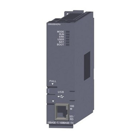
Page 149: Part Names
CHAPTER 5 PREPARATION AND SETUP Part Names This section describes each part and name of the CC-Link IE Controller Network module. QJ71GP21-SX QJ71GP21S-SX Name Description Indicates the operating status of the CC-Link IE Controller Network module. ( Page 148, Indicator LED Section 5.3 (1)) Used to connect an optical fiber cable to the CC-Link IE Controller Network module. - Page 150 (1) Indicator LEDs QJ71GP21-SX QJ71GP21S-SX Q J 7 1 G P 2 1 - S X Q J 7 1 G P 2 1 S - S X MODE D LINK MODE D LINK EXT.PW ERR. ERR. Name Description LED status ON, green Operating normally Hardware fault or watchdog timer error...
- Page 151 CHAPTER 5 PREPARATION AND SETUP (2) Station No. setting Station No. of the CC-Link IE Controller Network module is indicated. When indicating station No.15 X100 = 15 (3) IN and OUT connectors IN Forward loop, receiving Reverse loop, sending OUT Reverse loop, receiving OUT Forward loop, sending...
-
Page 152: Testing The Cc-Link Ie Controller Network Module
Testing the CC-Link IE Controller Network Module This section describes the tests of the CC-Link IE Controller Network module. Before starting up the system, the test is to be performed to check the CC-Link IE Controller Network module and cables. Perform each test according to the following. - Page 153 CHAPTER 5 PREPARATION AND SETUP Before power-on Set the RUN/STOP switch of the CPU module to STOP. Check the voltage supplied to the power supply module is within the specified range. Power-on Turn On the external power supply. Check the power supply module's POWER LED and the CC-Link IE Controller Network module's RUN LED are ON.
-
Page 154: Hardware Test
5.4.1 Hardware test Hardware test checks the hardware inside the CC-Link IE Controller Network module. (1) System configuration and parameter setting for other than redundant systems (a) System configuration Connect the CPU module to a programming tool. Do not connect optical fiber cables to the CC-Link IE Controller Network module. Normal station (No.4) Programming tool... - Page 155 CHAPTER 5 PREPARATION AND SETUP (2) System configuration and parameter setting for a redundant system The following is an example of when a hardware test is executed on the CC-Link IE Controller Network module on the system B in the system shown in (a) below. Set the operation mode of the redundant system to separate mode for the hardware test.
- Page 156 (c) Setting network parameters in the programming tool Set the mode of the system A to the online mode. Set the network parameters in the programming tool as shown below. Set the mode of the system B to the hardware test mode. Select "H/W Test"...
- Page 157 CHAPTER 5 PREPARATION AND SETUP (3) Executing the hardware test Start Powering OFF and ON or resetting the CPU module starts the test. During test execution The MODE LED flashes, and each of the LEDs turns ON and OFF in order (1 MODE D LINK ERR.
- Page 158 When the redundant system is in separate mode, power OFF and ON only system B or reset the CPU module of system When the redundant system is in separate mode, 1) Set online mode for the system B and write data to the system B CPU module. 2) Power OFF and ON only system B or reset the CPU module of system B.
-
Page 159: Self-Loopback Test
CHAPTER 5 PREPARATION AND SETUP 5.4.2 Self-loopback test Self-loopback test checks the hardware of the communication circuit of the CC-Link IE Controller Network module. Use a normal optical fiber cable when conducting the self-loopback test. (1) System configuration and parameter setting for other than redundant systems (a) System configuration Connect the programming tool to the CPU module. - Page 160 (2) System configuration and parameter setting for a redundant system The following is an example of when a self-loopback test is executed on the CC-Link IE Controller Network module on the system B in the system shown in (a) below. (a) System configuration Connect the programming tool to the control system CPU module.
- Page 161 CHAPTER 5 PREPARATION AND SETUP (c) Setting network parameters in the programming tool Set the mode of the system A to the online mode. Set the network parameters in the programming tool as shown below. Set the mode of the system B to the self-loopback test. Select "Self-Loopback Test"...
- Page 162 (3) Executing the self-loopback test Start Powering OFF and ON or resetting the CPU module starts the test. During test execution The MODE LED flashes, and each of the 10 LEDs turns ON and OFF in order (1 Note that, upon detection of an error, the test is immediately terminated (error completion).
- Page 163 CHAPTER 5 PREPARATION AND SETUP When the redundant system is in separate mode, power OFF and ON only system B or reset the CPU module of system When the redundant system is in separate mode, 1) Set the mode of system B to online mode, and write the data to the system B CPU module. 2) Power OFF and ON only system B or reset the CPU module of system B.
-
Page 164: Wiring
Wiring This section describes optical fiber cable connection and wiring precautions. (1) Wiring precautions (a) Use the optical fiber cable described in the following section. Page 38, Section 2.2.1 (b) There are restrictions on the bending radius of the optical fiber cable. For details, check the specifications of the cable to be used. - Page 165 CHAPTER 5 PREPARATION AND SETUP (2) Cable connection (a) Connection method Connect an optical fiber cable between OUT and IN as shown below. Note that there is no need to connect the cables in the order of station numbers. CC-Link IE Controller Network module Control station Normal station Normal station...
-
Page 166: Tests For Cc-Link Ie Controller Network Startup
Tests for CC-Link IE Controller Network Startup This section describes the tests to be executed at startup of the CC-Link IE Controller Network. The tests check whether the network operates properly or not at system startup. Perform each test according to the following. Start Configuring network system Connect CC-Link IE Controller Network modules... -
Page 167: Circuit Test
CHAPTER 5 PREPARATION AND SETUP 5.6.1 Circuit test Circuit test checks the network cable connection status, line status, and each station's parameter setting status from the control station. The following lists the test items that are checked in the circuit test. Item Description Detection of duplicated control... - Page 168 (b) Setting network parameters in the programming tool Set the control station to the circuit test mode. After setting the following network parameters in the programming tool, write them to the programmable controller. When a network contains a redundant system, pairing settings are required for network parameters of the control station. Select "Pairing"...
- Page 169 CHAPTER 5 PREPARATION AND SETUP (2) Executing the circuit test Control station Normal station Powering OFF and ON or resetting the CPU module Powering OFF and ON or resetting the CPU module activates the online mode. starts the test. During circuit test execution, data link stops on all stations.
- Page 170 ● When executing the circuit test, connect each cable properly between OUT and IN. Also, do not insert or remove a cable during test execution. (Doing so will result in error completion.) ● The circuit test result can be confirmed with the link special relay (SB0094, SB0095). ( Page 568, Appendix 1) ●...
-
Page 171: Station-To-Station Test
CHAPTER 5 PREPARATION AND SETUP 5.6.2 Station-to-station test Station-to-station test checks the condition of the cable connected between two stations (from OUT of the executing station to IN of the other station.) (1) System configuration and parameter setting for other than redundant systems (a) System configuration Connect the programming tool to the CPU module. - Page 172 (2) System configuration and parameter setting for a redundant system The following is an example of setting the CC-Link IE Controller Network module on the system B as an executing station in the system shown in (a) below. Set the operation mode of the redundant system to separate mode for the station-to-station test. (a) System configuration Connect the programming tool to the control system CPU module.
- Page 173 CHAPTER 5 PREPARATION AND SETUP (c) Setting network parameters in the programming tool Set the mode of the system A to the online mode. Set the network parameters in the programming tool as shown below. Set the mode of the system B (executing station) to the station-to-station test mode. In the "Redundant Setting"...
- Page 174 (3) Executing the station-to-station test Executing station Target station Powering OFF and ON or resetting the CPU module activates the online mode. Powering OFF and ON or resetting the CPU module During station-to-station test execution, data link starts the test. stops on the executing and target stations.
- Page 175 CHAPTER 5 PREPARATION AND SETUP ● When executing the station-to-station test, connect the cable properly between OUT and IN. Also, do not insert or remove a cable during test execution. (Doing so will result in error completion.) ● The station-to-station test result can be checked with the link special relay (SB0097). ( Page 568, Appendix 1)
-
Page 176: Test Before Cc-Link Ie Controller Network Operation
Test Before CC-Link IE Controller Network Operation This section describes the test performed before operation of the CC-Link IE Controller Network. The test checks, before system operation, whether transient transmission can be correctly routed in the network or not. 5.7.1 Communication test Communication test checks if transient transmission data can be properly routed from the own station to the communication target. - Page 177 CHAPTER 5 PREPARATION AND SETUP (d) Routing parameters of the relay station 1 (e) Routing parameters of the relay station 2 (3) Executing the communication test Open the "Communication Test" window in the programming tool. [Diagnostics] [CC IE Control Diagnostics] button Configure settings with reference to the description below.
- Page 178 (4) Checking the communication test result Upon completion of the communication test, the test result is displayed. If an error occurs, take corrective actions according to the error message.
-
Page 179: Chapter 6 Parameter Setting
CHAPTER 6 PARAMETER SETTING CHAPTER 6 PARAMETER SETTING This chapter describes the parameters of the CC-Link IE Controller Network module. Parameter List This list shows the CC-Link IE Controller Network module parameters. (1) Parameter list for the control station 1) Safety CPU 4) Process CPU 2) Basic model QCPU 5) Redundant CPU... - Page 180 CPU module Reference Item Description section 1) 2) 3) 4) 5) 6) Page 199, If the network contains a redundant system, set a Pairing Section 6.3.4 combination of stations of system A and system B. Network Page 200, Specify Reserved Set reserved station(s).
- Page 181 CHAPTER 6 PARAMETER SETTING (2) Parameter list for normal stations 1) Safety CPU 4) Process CPU 2) Basic model QCPU 5) Redundant CPU 3) High Performance model QCPU 6) Universal model QCPU CPU module Reference Item Description section Select the station type of the CC-Link IE Controller Network Type Network module.
-
Page 182: Network Settings
Network Settings Make settings for configuring the network. Open the "MELSECNET/CC IE/Ethernet Module Configuration" window in the programming tool. Project window [Parameter] [Network Parameter] [Ethernet/CC IE/MELSECNET] Configure settings with reference to the description below. Click the button. Item Description Network Type Select the station type of the CC-Link IE Controller Network module. - Page 183 CHAPTER 6 PARAMETER SETTING (1) Network Type Select the station type of the CC-Link IE Controller Network module. When the extended mode is selected using GX Works2, send points can be extended. For a Basic model QCPU or safety CPU, it is fixed to "CC IE Control (Normal Station)". Item Description Set this for the CC-Link IE Controller Network control station.
- Page 184 (6) Station No. When "Specify Station No. by Parameter" has been selected for the station No. setting method, set a station No. of the CC-Link IE Controller Network module. (Setting range for Universal model QCPU: 1 to 120, Default: None) (Setting range for other than Universal model QCPU: 1 to 64, Default: None) ●...
-
Page 185: Network Range Assignment
CHAPTER 6 PARAMETER SETTING Network Range Assignment To the control station, assign each station's send range required for cyclic transmission and configure supplementary settings for data communication. Network range assignments are set to the control station only. Normal stations perform cyclic transmission according to the range assigned at the control station. Configure the network setting. - Page 186 Item Description LX/LY Setting(1) For each block, set an I/O master station and I/O ranges used in communication using LX/LY between the I/O master and relevant stations. LX/LY Setting(2) Page 192, Section 6.3.2) Specify I/O Master Station For a Universal model QCPU, set stations that will share their cyclic data to the same shared Shared Group Setting group No.
-
Page 187: Lb/Lw Settings
CHAPTER 6 PARAMETER SETTING 6.3.1 LB/LW settings Set each station's send range in LB/LW to use it for communication using LB/LW. ( Page 61, Section 4.1.1) LB/LW settings can be divided into "LB/LW Setting(1)" and "LB/LW Setting(2)". Normally, setting only "LB/LW Setting(1)" is enough for communication using LB/LW. Set "LB/LW Setting(2)"... - Page 188 (1) Assuring 32-bit data integrity When settings are configured with the following four conditions met, 32-bit data integrity is automatically assured. Page 76, Section 4.1.5) • The start device No. of LB is a multiple of 20 • The points assigned per station in LB is a multiple of 20 •...
- Page 189 CHAPTER 6 PARAMETER SETTING Equal assignment is done in "LB/LW Setting(1)" of "Network Range Assignment". (3) Using identical point assignment The same points can be assigned to each station's send range in LB/LW. Specify the number of assignment points and click the button in the "Assignment the CC IE Control Network Range"...
- Page 190 (4) LB/LW setting examples (a) When assigning 512 points to each station's send range in LB/LW ("LB/LW Setting(1)") Control station Normal station Normal station Normal station No.1 No.2 No.3 No.4 Network range assignment LB/LW setting Link relay (LB) LB0 to LB1FF Station No.1 No.1 send range Station No.1...
- Page 191 CHAPTER 6 PARAMETER SETTING (b) When extending the send range of station No.1 to 1024 points without changing the assignment shown in (a) ("LB/LW Setting(2)") Control station Normal station Normal station Normal station No.1 No.2 No.3 No.4 Network range assignment LB/LW setting Link relay (LB) LB0 to LB1FF...
- Page 192 (c) When the network contains a station of a Basic model QCPU or safety CPU It is recommended to use "LB/LW Setting(2)" when a station on the network has a Basic model CPU or safety CPU. A setting example for "LB/LW Setting(1)" and "LB/LW Setting(2)" is shown below. Target range Item Description...
- Page 193 CHAPTER 6 PARAMETER SETTING • LB/LW Setting(1) • LB/LW Setting(2)
-
Page 194: Lx/Ly Settings
6.3.2 LX/LY settings For each block, set an I/O master station and I/O ranges used in communication using LX/LY between the I/O master and relevant stations. ( Page 66, Section 4.1.2) Set "LX/LY Setting(1)" for block 1, and "LX/LY Setting(2)" for block 2. Item Description Select an LX/LY assignment method. - Page 195 CHAPTER 6 PARAMETER SETTING (1) Specify I/O master station Set an I/O master station for each block to perform communication using LX/LY. Select a desired block in [Switch screens] to specify an I/O master station. Selecting a station No. and clicking the button will set the station as I/O master station.
- Page 196 (2) Using equal assignment The link device I/O range can be equally assigned between the I/O master and other stations. (LX/LY Setting(1) only) Open the "Assignment the CC IE Control Network Range" window in the programming tool. Page 183, Section 6.3) Click the button.
- Page 197 CHAPTER 6 PARAMETER SETTING (3) Example of "LX/LY Setting(1)" When specifying station No.1 as I/O master station and assigning 512 points to each I/O range for station No.2 to No.4 Control station Normal station Normal station Normal station No.1 No.2 No.3 No.4 1000...
-
Page 198: Shared Group
6.3.3 Shared group For a Universal model QCPU, set the stations that share their cyclic data to the same shared group No. (Setting range: None or 1 to 120, Default: None) This setting is common to "LB/LW Setting(1)", "LB/LW Setting(2)" and "LX/LY Setting(1)", and "LX/LY Setting(2)". Page 83, Section 4.1.8) (1) Directly entering a shared group No. - Page 199 CHAPTER 6 PARAMETER SETTING (3) Shared group setting example When setting stations No.2 and No.3 and stations No.4 and No.5 as two different shared groups: Shared group No.1 Shared group No.2 Control station Normal station Normal station Normal station Normal station No.1 No.2 No.3...
- Page 200 (4) Precautions (a) Do not perform the shared group setting for any station of a Universal model QCPU that does not support the group cyclic transmission function and stations other than Universal model QCPUs. If it is set by mistake, cyclic data of the stations in different shared groups will not refreshed to the devices of the CPU module.
-
Page 201: Pairing
CHAPTER 6 PARAMETER SETTING 6.3.4 Pairing When the network contains a redundant system, set a combination of stations of system A and system B. ( Page 138, Section 4.7) (1) Pairing setting example When setting station No.1 and No.2 as a pair: Redundant system System A (control System B (standby... -
Page 202: Reserved Station Specification
6.3.5 Reserved station specification Set reserved station(s). ( Page 88, Section 4.1.10) (1) Setting a reserved station Selecting a station No. and clicking the button will set it as a reserved station. The following window shows an example of when a station number 4 is reserved. -
Page 203: Supplementary Settings
CHAPTER 6 PARAMETER SETTING 6.3.6 Supplementary settings Set the constant link scan time, block data assurance per station, punctuality assurance, and the maximum number of transient transmissions for one station. Open the "Assignment the CC IE Control Network Range" window in the programming tool. Page 183, Section 6.3) Click the button. - Page 204 (3) Punctuality is guaranteed Set whether or not to assure the punctuality. (Default: Punctuality is guaranteed) If the "Punctuality is guaranteed" checkbox is checked, each station performs transient transmissions for the number of times specified in "Maximum No. of Transients in One Station", which keeps the link scan time constant.
-
Page 205: Network Operation Settings
CHAPTER 6 PARAMETER SETTING Network Operation Settings The IP address of the CC-Link IE Controller Network module is set to communicate data with Ethernet devices over CC-Link IE Controller Network. GX Works2 is required for the network operation settings. GX Developer cannot be used for setting. Set network setting parameters. -
Page 206: Refresh Parameters
Refresh Parameters 6.5.1 Refresh parameter setting Set the range of the transfer between the link devices of the CC-Link IE Controller Network module and CPU module devices. ● The number of refresh parameter settings per module is shown below. Number of settings High Performance model QCPU, Universal model QCPU Process CPU, Redundant CPU,... - Page 207 CHAPTER 6 PARAMETER SETTING Item Description Select a link device assignment method. Assignment Method • Points/Start: Enter link device points and start I/O numbers. • Start/End: Enter the start and end numbers of the link devices. Dev. Name Fixed to SB/SW Link Side Set the SB/SW transfer range.
- Page 208 (1) Refresh parameter setting example (a) When 512 points are assigned to each station's send range in LB/LW Control station Normal station Normal station Normal station No.1 No.2 No.3 No.4 CC-Link IE Controller Network module CPU module Station No.1 Station No.1 Station No.1 Station No.1 Station No.1...
- Page 209 CHAPTER 6 PARAMETER SETTING (b) When station No.1 is set as I/O master station of block 1 and 512 points are assigned to each I/O range for station No.2 to No.4 Control station Normal station Normal station Normal station No.1 No.2 No.3 No.4...
- Page 210 (c) Application example (when two CC-Link IE Controller Network modules are mounted for one programmable controller) CC-Link IE Controller CC-Link IE Controller Network module (1M Network module (2N CPU module 0 to 1FF 0 to 1FF Several link refresh ranges 300 to 4FF 300 to 4FF can be set separately.
- Page 211 CHAPTER 6 PARAMETER SETTING • Refresh parameters of CC-Link IE Controller Network module (1M • Refresh parameters of CC-Link IE Controller Network module (2N...
- Page 212 (d) Refresh parameters of a Basic model QCPU or safety CPU station Refresh only the LB/LW used for the CPU module because the B/W capacity of the CPU module (2K points) is too small. When data refresh is performed with station No.1 only, and not with station No.2 and No.3 Control station Normal station Normal station...
- Page 213 CHAPTER 6 PARAMETER SETTING (2) Checking the refresh parameters assignment image The refresh parameters assignment image for the network modules can be viewed in the network parameters of the programming tool. Open the "Setting the number of MELSECNET/CC IE/Ethernet Module Configuration" window in the programming tool.
-
Page 214: Change Of Transfer Target Cpu-Side Device
6.5.2 Change of transfer target CPU-side device When LB/LW transfer data exceeds the B/W capacity (8K points) of the CPU module, changing the B/W capacity or changing the transfer target CPU-side device to any other than B/W is needed. The following is an example of CPU-side device setting for 32K-point LB and 128K-point LW data transfer. For the Basic model QCPU or a safety CPU, refresh only the LB/LW that is used for the CPU module because the B/W capacity of the CPU module (2K points) is too small. - Page 215 CHAPTER 6 PARAMETER SETTING (a) PLC File Open the "PLC File" tab in the programming tool. Project window [Parameter] [PLC Parameter] Select the "Use the following file" radio button in "File register". Item Set value Corresponding Memory Standard RAM File Register Use the following file File Name CCIE_LW (Arbitrary)
- Page 216 (b) Device Open the "Device" tab in the programming tool. Project window [Parameter] [PLC Parameter] Change the device points as listed below. Device Points Item Device Before change After change Latch Relay (L) Device Link Relay (B) Link Register (W) File Register (ZR (R)) 128K File Register Extended Setting...
- Page 217 CHAPTER 6 PARAMETER SETTING (c) Refresh parameters Specify B as a target CPU-side device of transfer from LB. Specify W as a target CPU-side device of transfer from LW. (d) Program example In this program example, the following processing is performed when the send request turns ON. Stores D0 data in the extended link register, and transfers them to LW0 of the CC-Link IE Controller Network module through link refresh.
- Page 218 (2) When using a file register as an LW transfer destination (Except for Q00JCPU and QS001CPU) Link-side device CPU-side device CPU-side device setting method Register a 128K-point file register to the standard RAM or a memory LW0 to 1FFFF ZR0 to 131071 *1*2*3 card (RAM).
- Page 219 CHAPTER 6 PARAMETER SETTING (a) PLC File Open the "PLC File" tab in the programming tool. Project window [Parameter] [PLC Parameter] Select the "Use the following file" radio button in "File register". Item Set value Corresponding Memory Standard RAM File Register Use the following file File Name CCIE_LW (Arbitrary)
- Page 220 (b) Device Open the "Device" tab in the programming tool. Project window [Parameter] [PLC Parameter] Change the device points as listed below. Device Points Device Before change After change Latch Relay (L) Link Relay (B) Link Register (W) (c) Refresh parameters Specify B as a target CPU-side device of transfer from LB.
- Page 221 CHAPTER 6 PARAMETER SETTING (d) Program example In this program example, the following processing is performed when the send request turns ON. Stores D0 data in the file register, and transfers them to LW0 of the CC-Link IE Controller Network module through link refresh.
- Page 222 • Program example of when specifying an R in an access instruction to the file register • Switch the block No. by specifying it in the RSET instruction. Send CC-Link IE Controller request CPU module Network module RSET Block 0 R32767 RSET Block 1...
-
Page 223: Default Settings
CHAPTER 6 PARAMETER SETTING 6.5.3 Default settings Refresh parameters can be set properly according to the number of modules and the mounted positions given in Page 222, Section 6.5.3 (2). (1) Setting method By clicking the button on the refresh parameters window for each module, refresh parameters are set based on the number of modules and the position of the module. - Page 224 (2) Setting details Refresh parameters are set in the following manner depending on the number of modules and the mounted position. (a) For High Performance model QCPU, Process CPU, Redundant CPU, or Universal model QCPU • Transfer range of LB/LW Module mounting position No.
- Page 225 CHAPTER 6 PARAMETER SETTING • Transfer range of SB/SW Module mounting position No. of modules Module 1 Module 2 Module 3 Module 4 SB/SW SB/SW points SB/SW SB/SW SB/SW points points SB/SW SB/SW SB/SW SB/SW points points points SB/SW SB/SW SB/SW SB/SW SB/SW...
- Page 226 (b) For Basic model QCPU or safety CPU • Transfer range of LB/LW Module mounting position No. of modules Module 1 LB/LW 2048 points • Transfer range of SB/SW Module mounting position No. of modules Module 1 SB/SW SB/SW points...
-
Page 227: Interrupt Settings
CHAPTER 6 PARAMETER SETTING Interrupt Settings Set the conditions for sending an interrupt request to the CPU module. ( Page 135, Section 4.5) Up to 16 interrupt conditions can be set. Configure the network setting. ( Page 180, Section 6.2) Open the setting window in the programming tool. - Page 228 Item Description Setting range Input Format Select a format of the "Word Device Setting Value" column. DEC., HEX. (default: DEC.) Device Code Select an interrupt condition device. Device No. Detection Method Select detection timing of an interrupt for the device set in "Device Code" and "Device No."...
- Page 229 CHAPTER 6 PARAMETER SETTING (1) Intelligent function module interrupt pointer setting Interrupt (SI) Nos. of the CC-Link IE Controller Network module set in "Interrupt Settings" are linked to interrupt pointers of the CPU module. Open the "Intelligent Function Module Interrupt Pointer Setting" window of the programming tool. Project window [PLC Parameter] [PLC System]...
- Page 230 (2) Setting example (a) Starting the interrupt program of station No.15 when LB100 turns ON CC-Link IE Controller CC-Link IE Controller Network module Network module CPU module Station No.3 Station No.15 CPU module Interrupt program execution SM400 J7\B100 Receive processing LB100 IRET LB100...
- Page 231 CHAPTER 6 PARAMETER SETTING (b) Starting the interrupt program of station No.15 when Data link status of own station (SB0049) turns ON (data link error occurrence) CC-Link IE Controller CC-Link IE Controller Network module Network module CPU module Station No.3 Station No.15 CPU module Interrupt program...
- Page 232 (c) Starting the interrupt program of station No.15 when data sent from station No.3 with the SEND instruction are received in the channel specified in the RECVS instruction (channel 5) CC-Link IE Controller CC-Link IE Controller Network module Network module CPU module Station No.3 Station No.15...
-
Page 233: Redundant Settings
CHAPTER 6 PARAMETER SETTING Redundant Settings For Redundant CPUs, set the operation mode of the CC-Link IE Controller Network module on system B. ( Page 138, Section 4.7) Configure the network setting. ( Page 180, Section 6.2) Open the "Redundant settings" window in the programming tool. Project window [Parameter] [Network Parameter]... -
Page 234: Interlink Transmission Parameters
Interlink Transmission Parameters Set the link device transfer range between network modules. ( Page 89, Section 4.1.11) ● Up to 64 link device transfer range settings are available for each link of network modules. ● When setting of 65 or more link device transfer ranges is required, use link direct devices in the sequence program to perform the link transfer. - Page 235 CHAPTER 6 PARAMETER SETTING Item Description Select a link device assignment method. Assignment Method • Points/Start: Enter link device points and start I/O numbers. • Start/End: Enter the start and end numbers of the link devices. Displays the module numbers and network types of the transfer source and Transfer from/Transfer to transfer target.
- Page 236 (1) Precautions (a) Set the transfer target link device within the own station's send range of the transfer target network module. (If it is set to an area outside the own station's send range of the transfer target network module, the area is overwritten at the time of link scan.) Network module 1 Network module 2...
- Page 237 CHAPTER 6 PARAMETER SETTING (c) Interlink transmission is performed between the control station and normal station. (The MELSECNET/H standby station cannot be the target of the interlink transmission.) (d) The transfer source link device data can be transferred to multiple network modules. (An identical transfer source link device can be specified.) (2) Interlink transmission parameter setting example The interlink transmission parameters for the following assignment are shown in this section.
- Page 238 • Interlink transmission parameter setting for Module 2 Module 1 (3) Checking the interlink transmission parameters assignment image The interlink transmission parameters assignment image of the network modules can be viewed in the network parameters of the programming tool. Open the "MELSECNET/CC IE/Ethernet Module Configuration"...
- Page 239 CHAPTER 6 PARAMETER SETTING If any transfer target device is overlapped with the link refresh range (red), check the interlink transmission parameters or refresh parameters. ( Page 204, Section 6.5)
-
Page 240: Routing Parameters
Routing Parameters Set a relay station in the own network to transmit data to another network. Set the routing parameters under one of the following conditions. • When using the dedicated instruction to perform transient transmission to a different network ( Page 324, CHAPTER 9) •... - Page 241 CHAPTER 6 PARAMETER SETTING (1) Concept of routing parameters To each station on the network, set a relay station in the own network to transmit data to another network. Routing parameters set to each station on Network No. Network No. (Relay station) Network No.
- Page 242 (2) Precautions (a) Transient transmission range Communication can be made with a station on the eighth farthest network system. (No. of relay stations: 7) (b) Access conditions when the station No. of the request source, request target or CC- Link IE Controller Network relay station is 65 or more. When the station number of the request source or request destination is 65 or more, access can be made under the following conditions.
- Page 243 CHAPTER 6 PARAMETER SETTING (c) When networks are connected in a loop configuration Be sure to configure the settings correctly so that requests and responses will take the same route. A response from the request target is passed back to the station that relayed the request. Therefore, if a different route is set, data cannot be transferred and an error will occur.
- Page 244 (e) When a transmission passes through a redundant system Changed by RTWRITE instruction. Routing parameter Routing parameter Station No.3 Station No.3 Relay Relay Target Relay Relay Target Network No. Station No. Network No. Network No. Network No. Station No. Network No.2 Network No.2 Station No.1 Station...
- Page 245 CHAPTER 6 PARAMETER SETTING (3) Routing parameter setting example The routing parameters for each station in the following system configuration are shown in this section. Any station can transmit transient data to any other station. Network No.1 Network No.3 (Relay station 1) (Relay station 2) Network No.2 (a) Routing parameters for each station of the network No.1...
-
Page 246: Chapter 7 Processing Time
CHAPTER 7 PROCESSING TIME This chapter explains the processing time of the CC-Link IE Controller Network. Link Scan Time The link scan time (LS) of the CC-Link IE Controller Network is obtained from the following calculation formulas. (1) For other than the Extended Mode (a) When assigned in LB/LW settings (1) and LX/LY settings (1) LS = [KB + (n ×... -
Page 247: Link Refresh Time
CHAPTER 7 PROCESSING TIME Link Refresh Time The following are calculation formulas for the link refresh time (increase in END processing time of the CPU module). (1) For Basic model QCPUs, High Performance model QCPUs, Process CPUs, Redundant CPUs, and Universal model QCPUs) LB LX LY SB KM1 KM2 LW SW... - Page 248 KM2(×10 KM3(×10 CPU type KM1(×10 Extension Extension Main base Main base base base Q00JCPU 1300 0.67 1.50 Basic model Q00CPU 1100 0.66 1.44 — — QCPU Q01CPU 0.61 1.42 High Q02CPU 0.48 1.20 0.60 1.32 Performance model Q02H/Q06H/Q12H/Q25HCPU 0.41 0.97 0.53 1.09 QCPU...
-
Page 249: Interlink Transmission Time
CHAPTER 7 PROCESSING TIME 7.2.1 Interlink transmission time The following are the calculation formulas for the interlink transmission time. (1) For High Performance model QCPUs, Process CPUs, and Redundant CPUs α =KM4+KM5× [ms] L: Interlink transmission time Total number of actual link refresh points in LB LW: Total number of actual link refresh points in LW KM4 and KM5: Constant... - Page 250 (2) For Universal model QCPUs Universal model QCPUs transfer interlink data in several batches. (a) Interlink transmission time taken in one END processing (KM5 n1) KM6 [ms] L: Interlink transmission time taken in one END processing Number of lines where interlink transmission parameters are set LBr: Total number of LB points, which are set with interlink transmission parameters LWr: Total number of LW points, which are set with interlink transmission parameters KM4, KM5, and KM6:...
- Page 251 CHAPTER 7 PROCESSING TIME (b) Interlink transmission time required for transferring data of all the set points [ms] aL1: Interlink transmission time required for transferring data of all the set points LBr: Total number of LB points, which are set with interlink transmission parameters LWr: Total number of LW points, which are set with interlink transmission parameters KM7: Constants KM7 (×...
-
Page 252: Cyclic Transmission Delay Time
Cyclic Transmission Delay Time 7.3.1 Cyclic transmission delay time The following shows calculation formulas for cyclic transmission delay time (the time until completion of data transmission). (1) In the case of a single network system (a) When a non-Redundant CPU receives transmission data Transmission delay time [ms] for ST >... - Page 253 CHAPTER 7 PROCESSING TIME (2) In the case of a multi-network system The following shows the cyclic transmission delay time for the case where link device data are transferred to another network with the interlink transmission function. Transmission delay time (For other than Universal model QCPUs) = (ST + T) + (LS ) + MR + KM + MT + (LS ) + R [ms]...
-
Page 254: Transmission Delay Time Calculation Example
7.3.2 Transmission delay time calculation example This section provides a calculation example of the cyclic transmission delay. (1) Transmission delay time in a single network system (a) System configuration and conditions Item Description CPU module Q06HCPU Total number of stations per network 8 stations LB/LW 1024 points for each... - Page 255 CHAPTER 7 PROCESSING TIME (d) Cyclic transmission delay time ( Page 250, Section 7.3.1) Transmission delay time for ST < LS [ms] Calculated value Station-based block data assured (ST + T) + LS × 1 + (SR + R) × 1.5 Normal value (1 + 0.80) + 1.58 ×...
- Page 256 (a) System configuration and conditions Item Description CPU module Q06UDHCPU Total number of stations per network 3 stations LB/LW 1024 points for each Total link device points LX/LY 0 point SB/SW 512 points for each Sequence scan time File register None 3 ...
- Page 257 CHAPTER 7 PROCESSING TIME (c) Link refresh time ( Page 245, Section 7.2) [Interlink transmission time for the Universal model QCPU] (KM5 KM6 [ms] (1) Sending-side link refresh time, receiving-side link refresh time T, R = 90 × 10 + 0.41 × 10 ×...
-
Page 258: Dedicated Instruction Transmission Delay Time
Dedicated Instruction Transmission Delay Time 7.4.1 Link dedicated instruction transmission delay time The following shows the calculation formulas for the link dedicated instruction transmission delay time (the time taken from issuing an instruction until receiving a response). (1) For a single network system (a) Transmission delay time for the SEND/RECV/RECVS/ZNRD/ANWR instruction Sending station Transmission delay time of when the receiving station is a non-redundant system [ms]... - Page 259 CHAPTER 7 PROCESSING TIME (b) Transmission delay time for the READ/WRITE instruction Sending station Transmission delay time of when the receiving station is a non-redundant system [ms] TD1 = {(ST + T) × 2 + LS × 11 + (SR + R)} × m Non-redundant system Redundant system TD1 + TsT ×...
- Page 260 (c) Transmission delay time for the SREAD/SWRITE instruction Sending station Transmission delay time of when the receiving station is a non-redundant system [ms] TD1 = {(ST + T) × 2 + LS × 11 + (SR + R)} × (m + 1) Non-redundant system Redundant system TD1 + TsT ×...
- Page 261 CHAPTER 7 PROCESSING TIME (d) Transmission delay time for the REQ/RRUN/RSTOP/RTMRD/RTMWR instruction Sending station Transmission delay time of when the receiving station is a non-redundant system [ms] TD1 = (ST + T) × 2 + LS × 11 + (SR + R) Non-redundant system Redundant system TD1 + TsT ×...
- Page 262 (2) For a multi-network system The following shows the calculation formula for the link dedicated instruction transmission delay time that is required to access a station on another network. Each processing time is calculated from the formulas in Page 256, Section 7.4.1 (1). When routing through three or more networks, the processing time between the relay stations are added.
-
Page 263: Cc-Link Dedicated Instruction Transmission Delay Time
CHAPTER 7 PROCESSING TIME 7.4.2 CC-Link dedicated instruction transmission delay time The following shows the calculation formulas for the CC-link dedicated instruction transmission delay time (the time taken from issuing an instruction until receiving a response). (1) Transmission delay time for the RIRD/RIWT instruction Sending station Transmission delay time of when the receiving station is a non-redundant system [ms] TD1 = (ST + T) ×... -
Page 264: Cyclic Data Retention Time For System Switching In A Redundant System
Cyclic Data Retention Time for System Switching in a Redundant System This section gives calculation formulas for cyclic data retention time that is taken when a system switching occurs in a redundant system. (1) When the control system power supply module is faulty or powered off or when the control system CPU is faulty or reset (a) When a redundant system is the control station and "System switching time of Redundant CPU (Tsw) <... - Page 265 CHAPTER 7 PROCESSING TIME (b) When a redundant system is the control station and "System switching time of Redundant CPU (Tsw) > Control station switching time (Csw)" is met Th = Tsw + SS × 2 [ms] Th: Cyclic data retention time Tsw: System switching time of Redundant CPU Csw: Control station switching time = 20 + Constant link scan set value ( Page 201, Section 6.3.6 (1))
- Page 266 (c) When the redundant system is a normal station Th = Tsw + SS × 2 [ms] Cyclic data retention time Tsw: System switching time of Redundant CPU Sequence scan time of Redundant CPU For details, refer to the following. QnPRHCPU User's Manual (Redundant System) Normal station Communication error station...
- Page 267 CHAPTER 7 PROCESSING TIME (2) When a stop error occurs in the control system CPU, System switching instruction is executed, system switching is executed from the programming tool, or system switching is requested from another network module Th = Tsw + SS [ms] Cyclic data retention time Tsw: System switching time of Redundant CPU Sequence scan time of Redundant CPU...
- Page 268 (3) When system switching is requested from the CC-Link IE Controller Network module (own station) Th = 150 + Td + Tc + Tsw + (SS × 2) [ms] Cyclic data retention time Data link monitoring time System switching monitoring time Tsw: System switching time of Redundant CPU Sequence scan time of Redundant CPU Set it by "Network Range Assignment"...
-
Page 269: Chapter 8 Programming
CHAPTER 8 PROGRAMMING CHAPTER 8 PROGRAMMING This chapter describes the programming of the CC-Link IE Controller Network module. Program Example of a Single Network System The programming procedure of when communications are performed in a single network system is described in Page 267, Section 8.1.1 to Page 285, Section 8.1.6. -
Page 270: Setting And Communication Contents
8.1.2 Setting and communication contents Consider each station send range of LB/LW and set the parameters. Using a parameter sheet is helpful to determine each station's send range of LB/LW and parameters. ( Page 645, Appendix 5) Before considering parameters of each station, consider each station send range of LB/LW with the link device assignment sheet. - Page 271 CHAPTER 8 PROGRAMMING (1) Setting of control station (No. 1) (a) Quantity setting Fill in the quantity setting parameter sheet. ( Page 651, Appendix 5.2) Control station (No. 1) CC-Link IE Controller Network module Item CC IE Control (Control Station) CC IE Control (Control Station) CC IE Control (Normal Station) CC IE Control (Normal Station)
- Page 272 (b) Network range assignment In the program example in this section, each station send range of LB/LW is assigned 512 points. Use the default setting for the supplementary setting. Control station Normal station Normal station Normal station No.1 No.2 No.3 No.4 No.1 send range No.1...
- Page 273 CHAPTER 8 PROGRAMMING Item Setting contents Constant Link Scan ms (Range: 1 to 500) Checked Block Data Assurance per Block data assurance per station is Station available Not checked Checked Punctuality is guaranteed Transient Setting Not checked Maximum No. of Transients in One times (Range: 1 to 10) Station Complete settings in the programming tool based on the contents filled in the parameter sheet.
- Page 274 (c) Refresh parameters In the program example in this section, the following refresh parameters are assigned (control station (station No. 1) for CC-Link IE Controller Network modules on station numbers 1 to 4. CC-Link IE Controller CPU module Network module 0 to 1FF Station No.1 Station No.1...
- Page 275 CHAPTER 8 PROGRAMMING (2) Setting of normal station (No. 2 to 4) (a) Quantity setting Fill in the quantity setting parameter sheet. ( Page 651, Appendix 5.2) Normal station (No. 2) CC-Link IE Controller Network module Item CC IE Control (Control Station) CC IE Control (Control Station) CC IE Control (Normal Station) CC IE Control (Normal Station)
- Page 276 Complete settings in the programming tool based on the contents filled in the parameter sheet. Set the same setting for the normal stations (No. 2 to 4). Set a station No. within the range of 2 to 4. (b) Refresh parameters Set the refresh parameters.
-
Page 277: Program Example Of Cyclic Transmission
CHAPTER 8 PROGRAMMING 8.1.3 Program example of cyclic transmission The following shows a program example of cyclic transmission. (1) Overview of the program example D0 of the control station (No. 1) is sent to Y50 to Y5F of the normal station (No. 2) through cyclic transmission. In the program example in this section, an interlock is established with link relay (LB) and cyclic data is sent. - Page 278 (2) Devices used in the program example (a) Devices used by control station (No. 1) • Link special relay (SB) and link special register (SW) Device Description Device Description SB0049 Data link status of own station SW00B0.1 Cyclic transmission status of station No. 2 •...
- Page 279 CHAPTER 8 PROGRAMMING (3) Program example The following shows a program example. (a) Program example of control station (No. 1) When creating a cyclic communication program, establish an interlock using Data link status of own station (SB0049) and Cyclic transmission status (SW00B0). Communication with normal station (No.2)
-
Page 280: Program Example Of Transient Transmission
8.1.4 Program example of transient transmission The following shows a program example of transient transmission. (1) Overview of the program example In the program example in this section, the following transient transmission is performed using the READ and WRITE instructions. Control station Normal station No.1... - Page 281 CHAPTER 8 PROGRAMMING (2) Devices used in the program example (a) Special relay (SM), link special relay (SB), and link special register (SW) Device Description Device Description SM402 Turned ON for only one scan after RUN SW00A0.1 Baton pass status of station No.2 SB0047 Baton pass status of own station —...
- Page 282 (b) WRITE instruction Device Item Setting value 0001 (With arrival confirmation, clock data at the time of error (S1)+0 D1020 Execution/Error completion type completion is not set) (S1)+1 D1021 Completion status — (Set by system, no setting required) (S1)+2 D1022 Channel used by own station 0000 (Control CPU)
- Page 283 CHAPTER 8 PROGRAMMING (4) Program example The following shows a program example of transient transmission. The following sequence program is written to the CPU module of control station (No. 1). Control data setting of READ instruction Control data setting of WRITE instruction (To the next page)
- Page 284 Execution of READ instruction Processing program for read completion Processing program for normal completion Processing program for error completion Error code reading, etc. Execution of WRITE instruction Processing program for write completion Processing program for normal completion Processing program for error completion Error code reading, etc.
-
Page 285: Program Example Of An Interrupt Request
CHAPTER 8 PROGRAMMING 8.1.5 Program example of an interrupt request The following shows a program example of an interrupt request. (1) Overview of the program example In the program example in this section, the interrupt program of station No. 2 is activated when the Data link status of own station (SB0049) is ON (data link error occurrence). - Page 286 (3) Devices used in the program example (a) Special relay (SM) Device Description Device Description SM400 Always ON — (b) Devices used by the user Device Description Device Description Interrupt pointer when Data link status of own — station (SB0049) is ON. (4) Program example The following shows a program example of interrupt request.
-
Page 287: Program Example Of Error Detection In Other Stations
CHAPTER 8 PROGRAMMING 8.1.6 Program example of error detection in other stations The following shows a program example of error detection in other stations. (1) Overview of the program example In the program example in this section, the baton pass status and the cyclic transmission status of each station is monitored and some network errors in other stations are detected in a system configured with three stations. - Page 288 (3) Program example The following shows a program example of error detection in other stations. The setting value of error monitoring timer is 200ms. Processing program for error completion...
-
Page 289: Program Example Of A Multi-Network System
CHAPTER 8 PROGRAMMING Program Example of a Multi-network System The programming procedure of when communications are performed in a multi-network system is described in Page 287, Section 8.2.1 to Page 303, Section 8.2.4. 8.2.1 System configuration Configure the system using the procedures described in this section. (1) System configuration example Configure the system shown below. -
Page 290: Setting And Communication Contents
8.2.2 Setting and communication contents Consider each station send range of LB/LW and set the parameters. Using the parameter sheet is helpful for considering each station send range of LB/LW and parameters. ( Page 645, Appendix 5) Before considering parameters of each station, consider each station send range of LB/LW with the link device assignment sheet. - Page 291 CHAPTER 8 PROGRAMMING (1) Setting of control station (1M (a) Quantity setting Page 651, Consider the quantity setting with the quantity setting parameter sheet. ( Appendix 5.2 Control station (1M CC-Link IE Controller Network module Item CC IE Control (Control Station) CC IE Control (Control Station) CC IE Control (Normal Station) CC IE Control (Normal Station)
- Page 292 (b) Network range assignment In the program example in this section, each station send range of LB/LW is assigned 512 points. Use the default setting for the supplementary setting. CC-Link IE Controller Network module Control Normal Control Normal station station station station Network No.1...
- Page 293 CHAPTER 8 PROGRAMMING Item Setting contents Constant Link Scan ms (Range: 1 to 500) Checked Block Data Assurance per Block data assurance per station is Station available Not checked Checked Punctuality is guaranteed Transient Setting Not checked Maximum No. of Transients in One times (Range: 1 to 10) Station Complete settings in the programming tool based on the contents filled in the parameter sheet.
- Page 294 (c) Refresh parameters Set the following refresh parameters for the control station (1M CC-Link IE Controller CPU module Network module 0 to 1FF 0 to 1FF 200 to 3FF 200 to 3FF 0 to 1FF 0 to 1FF 200 to 3FF 200 to 3FF : Link refresh range Fill in the refresh parameter sheet.
- Page 295 CHAPTER 8 PROGRAMMING (d) Routing parameters Set routing parameters for the control station (1M 1) with the following system configuration. CC-Link IE Controller Network module Control Normal Control Normal station station station station Network No.1 Network No.2 Fill in the routing parameter sheet. ( Page 662, Appendix 5.7) Control station (1M "To go to network No.2, data passes through station No.2 of its own network No.1."...
- Page 296 (2) Setting of normal station (1N 2) and control station (2M (a) Quantity setting Fill in the quantity setting parameter sheet. ( Page 651, Appendix 5.2) Normal station (1N 2), control station(2M CC-Link IE Controller Network module Item CC IE Control (Control Station) CC IE Control (Control Station) CC IE Control (Normal Station) CC IE Control (Normal Station)
- Page 297 CHAPTER 8 PROGRAMMING (b) Network range assignment (set in control station (2M Determine network range assignment. The network range assignment and supplementary setting of the control station (2M 1) are the same as those of the control station (1M 1). ( Page 289, Section 8.2.2 (1)) Complete settings in the programming tool based on the contents filled in the parameter sheet.
- Page 298 (c) Refresh parameters Set the following refresh parameters to the normal station (1N 2) and the control station (2M CC-Link IE Controller CC-Link IE Controller CPU module Network module Network module Normal station (1N Control station (2M 0 to FF 0 to 1FF 0 to 1FF 200 to 2FF...
- Page 299 CHAPTER 8 PROGRAMMING Complete settings in the programming tool based on the contents filled in the parameter sheet. • Refresh parameter setting (Normal station (1N • Refresh parameter setting (Control station (2M...
- Page 300 (d) Interlink transmission parameters In the program example in this section, the following interlink transmission parameters are set. CC-Link IE Controller CC-Link IE Controller Network module Network module CPU module Normal station (1N Control station (2M 0 to FF 0 to 1FF 100 to 1FF 200 to 2FF 200 to 2FF...
- Page 301 CHAPTER 8 PROGRAMMING Complete settings in the programming tool based on the contents filled in the parameter sheet. • Setting of interlink transmission parameters (Normal station (1N • Setting of interlink transmission parameters (Control station (2M...
- Page 302 (3) Setting of normal station (2 (a) Quantity setting Page 651, Appendix 5.2) Fill in the quantity setting parameter sheet. Normal station (2N CC-Link IE Controller Network module Item CC IE Control (Control Station) CC IE Control (Control Station) CC IE Control (Normal Station) CC IE Control (Normal Station) Network Type CC IE Control Extended Mode (Control Station)
- Page 303 CHAPTER 8 PROGRAMMING Complete settings in the programming tool based on the contents filled in the parameter sheet. (b) Refresh parameters For the normal station (2N 2), set refresh parameters same as those of the control station (1M 1). ( Page 289, Section 8.2.2 (1))
- Page 304 (c) Routing parameters For the normal station (2N 2), set routing parameters in the following system configuration. CC-Link IE Controller Network module Control Normal Control Normal station station station station Network No.1 Network No.2 Fill in the routing parameter sheet. ( Page 662, Appendix 5.7) Normal station (2N "To go to network No.1, data passes through station No.1 of its own network No.2."...
-
Page 305: Program Example Of Cyclic Transmission
CHAPTER 8 PROGRAMMING 8.2.3 Program example of cyclic transmission The program example of cyclic transmission of multi-network system is the same as the program example of single network system. ( Page 275, Section 8.1.3) 8.2.4 Program example of transient transmission The program example of transient transmission of multi-network system is the same as the program example of single network system. - Page 306 (4) Program example The following shows the differences between a program example ( Page 281, Section 8.1.4 (4)) of performing transient transmission in a single network system and a program example of performing transient transmission to another network. The devices used in the program example are the same as those of the program example of the single network system.
- Page 307 CHAPTER 8 PROGRAMMING Establish an interlock using Baton pass status of relay station (SW00A0.1) in the same network. Processing program for read completion Processing program for normal completion Processing program for error completion Processing program for write completion Processing program for normal completion Processing program for error completion...
-
Page 308: Using Link Special Relay (Sb) And Link Special Register (Sw)
Using Link Special Relay (SB) and Link Special Register (SW) This section explains how to use link special relay (SB) and link special register (SW). Remark • Details on link special relay (SB): Page 568, Appendix 1 • Details on link special register (SW): Page 584, Appendix 2 (1) Cyclic transmission stop/restart Cyclic transmission stop/restart is executed through the CC IE Control diagnostics, but it also can be executed... - Page 309 CHAPTER 8 PROGRAMMING (b) Cyclic transmission restart of another station In the following link special register (SW), specify a station for restarting cyclic transmission. • Specification of target station Link stop/startup direction (SW0000) • Specification of station No. Link stop/startup direction (SW0001 to SW0008) •...
- Page 310 (d) Cyclic transmission restart of own station Turn Link startup (own station) (SB0000) ON. When the CC-Link IE Controller Network module accepts the request, Cyclic transmission start accept status (own station) (SB004C) is turned ON. When the cyclic transmission restart is completed, Cyclic transmission start completion status (own station) (SB004D) is turned ON.
- Page 311 CHAPTER 8 PROGRAMMING (2) Checking data link The data link status is checked through the CC IE Control diagnostics, but it also can be checked with link special relay (SB) and link special register (SW). ( Page 526, Section 10.3) (a) Check the data link status of other stations Link scan time etc., can be checked in SW005A to SW005B and SW0060 to SW0062.
- Page 312 (3) Checking transient transmission errors Transient transmission errors are checked through the CC IE Control diagnostics, but they also can be checked with link special relay (SB) and link special register (SW). ( Page 526, Section 10.3) (a) Checking stations where transient transmission errors have occurred When a transient transmission error occurs, Transient error of each station (SB0170) is turned ON.
- Page 313 CHAPTER 8 PROGRAMMING (4) Cable fault detection Cable fault is checked through the CC IE Control diagnostics, but it also can be checked with link special relay (SB) and link special register (SW). ( Page 526, Section 10.3) (a) Checking for cable faults of other stations If another station receives an error frame through a cable fault, either of the following link special relay (SB) is turned ON.
- Page 314 (b) Checking for cable faults of own station When an own station cable has fault, any of SB0066 to SB0069 and SB006C to SB006F is turned The rate of line error occurrence can be checked in SW0068 to SW0069 and SW006A to SW006B. When Clear IN-side transmission error counter (SB0007) is turned ON, SB006E and SW0068 to SW0069 can be cleared.
- Page 315 CHAPTER 8 PROGRAMMING (5) Detection of cable disconnection and cable insertion errors Cable disconnections and cable insertion errors are checked through the CC IE Control diagnostics, but they also can be checked with link special relay (SB) and link special register (SW). ( Page 526, Section 10.3) (a) Checking for cable disconnection and cable insertion errors When there is a cable disconnection or cable insertion error, loopback occurs.
- Page 316 • When station No. 1, 2, and 4 are monitored The IN-side cable insertion error status of station No. 3 is stored into the link special register (SW) in values as shown below. Description Value to be stored SW0080 OUT-side loopback station No. SW0081 OUT-side loopback factor SW0082...
- Page 317 CHAPTER 8 PROGRAMMING (6) Detection of duplicated control station or station No. The control station duplication and station No. duplication are checked through the CC IE Control diagnostics, but they also can be checked with link special relay (SB) and link special register (SW). ( Page 526, Section 10.3) Check the station No.
- Page 318 (8) Checking test results for CC-Link IE Controller Network startup The test result is checked through the CC IE Control diagnostics, but it also can be checked with link special relay (SB) and link special register (SW). ( Page 164, Section 5.6) (a) Checking circuit test results When the normal station accepts a circuit test request from the control station, Circuit test request from other station (SB0098) of the normal station is turned ON.
- Page 319 CHAPTER 8 PROGRAMMING (b) Checking parameter status of own station When receiving parameters is completed, Parameter receive status (SB0054) is turned OFF. When parameters have an error, Received parameter error (SB0055) is turned ON and an error code is stored in Parameter setting status (SW0055). The presence or absence of parameters can be checked with Parameter information (SW0054).
- Page 320 (10)Checking CPU module status The CPU module status is checked through the CC IE Control diagnostics, but it also can be checked with link special relay (SB) and link special register (SW). ( Page 526, Section 10.3) (a) Checking the CPU module status of other stations Whether the CPU module is in RUN status or STOP status can be checked with the following link special relay (SB) and link special register (SW).
- Page 321 CHAPTER 8 PROGRAMMING (11)Checking the status of communications between a CC-Link IE Controller Network module and a CPU module The status of communications between a CC-Link IE Controller Network module and a CPU module can be checked with link special relay (SB) and link special register (SW). ( Page 526, Section 10.3) If an error occurs in communications between a CC-Link IE Controller Network module and a CPU module, Module status (SB0020) is turned ON.
- Page 322 (13)Checking normal (own) station No. setting status The normal (own) station No. setting status can be checked not only by CC IE Control diagnostics but also with the link special relay (SB) and link special register (SW). ( Page 526, Section 10.3) (a) When station No.
- Page 323 CHAPTER 8 PROGRAMMING (b) RECV instruction When data are stored in the own station channel area, the corresponding RECV execution request flag (SB0030 to SB0037) turns ON. Use a RECV execution request flag as a start contact to execute the RECV instruction. Upon completion of the RECV instruction, the RECV execution request flag turns OFF.
- Page 324 (d) RRUN/RSTOP/RTMRD/RTMWR instruction Create an interlock with the following link special relay (SB) and link special register (SW) before executing an instruction. • Baton pass status (own station) (SB0047) • Baton pass status of each station (SB00A0) (When all stations are specified) •...
- Page 325 CHAPTER 8 PROGRAMMING (15)Checking the redundant system status The redundant system status can be checked not only from CC IE Control diagnostics but also by link special relay (SB) and link special register (SW). ( Page 526, Section 10.3) (a) Disabling system switching due to a data link error Page 141, Section 4.7.2) Set Data-link-error-induced system switching disable flags (SB0017) of both systems to ON.
-
Page 326: Chapter 9 Dedicated Instructions
CHAPTER 9 DEDICATED INSTRUCTIONS A "dedicated instruction" is defined as an instruction designed to make programming easy for use of the intelligent function module. This chapter describes the dedicated functions available for the CC-Link IE Controller Network module. List of Dedicated Instructions and Available Devices (1) Dedicated instructions Dedicated instructions can be used for transient transmission with a programmable controller on another station. - Page 327 CHAPTER 9 DEDICATED INSTRUCTIONS Dedicated Reference Application Description instruction section Page 443, RRUN Instructs a programmable controller on another station to perform remote RUN. Section 9.14 Remote RUN/STOP (for Q series) Instructs a programmable controller on another station to perform remote Page 451, RSTOP Section 9.15...
-
Page 328: Precautions For Dedicated Instructions
Precautions for Dedicated Instructions 9.2.1 Precautions for dedicated instructions (common) The following explains precautions for using dedicated instructions. (1) Change of the data specified with dedicated instructions Do not change any data (control data, etc.) until execution of the dedicated instruction is completed. (2) When a dedicated instruction has not been completed Dedicated instructions must be executed in online. - Page 329 CHAPTER 9 DEDICATED INSTRUCTIONS (c) Using the service processing setting (For Universal model QCPUs) In the service processing setting of the PLC parameter (PLC system) in the programming tool, secure time of 2ms to 3ms for service processing. Remark For details on the COM instruction, refer to the following. Programming Manual (Common Instructions) for the CPU module used (4) Executing a dedicated instruction from a redundant system If a system switching occurs during instruction execution, execution of the instruction is stopped and its...
-
Page 330: Precautions For Link Dedicated Instructions
9.2.2 Precautions for link dedicated instructions The following explains precautions for using link dedicated instructions. (1) When executing multiple link dedicated instructions at the same time When executing multiple link dedicated instructions at the same time, make sure that the channels for them are not duplicated. - Page 331 CHAPTER 9 DEDICATED INSTRUCTIONS Remark The following table lists operations when link dedicated instructions are executed at the same time. Instruction to be executed concurrently Link dedicated instruction READ/SREAD/WRITE/SWRITE/REQ/SEND/RECV/ ZNRD ZNWR RECVS/RRUN/RSTOP/RTMRD/RTMWR READ/SREAD/WRITE/SWRITE/REQ/SEND/RECV/ RECVS/RRUN/RSTOP/RTMRD/RTMWR ZNRD × ZNWR × : Executable, : Executable if not using the same channel, ×: Not executable (The latter one is not executed.) When the same channel is used, the latter instruction is not executed.
- Page 332 (b) When CPU No. is specified for Target station's CPU type of the instruction The instruction is not executed on a station where the CPU No. of the control CPU is different from the one specified for Target station's CPU type. (Note that no error will be detected on the request source.) When executing WRITE instruction under the following conditions: Target station's CPU type...
-
Page 333: Precautions For Cc-Link Dedicated Instructions
CHAPTER 9 DEDICATED INSTRUCTIONS 9.2.3 Precautions for CC-Link dedicated instructions The following explains precautions for using CC-link dedicated instructions. (1) Concurrent execution of multiple CC-Link dedicated instructions Concurrent execution of multiple CC-Link dedicated instructions is not allowed. Complete one CC-Link dedicated instruction execution, and then execute the next. The completion status of the CC-Link dedicated instructions can be confirmed with the completion device. -
Page 334: Jp/Gp. Read (Data Read From Programmable Controllers On Other Stations)
JP/GP. READ (Data Read from Programmable Controllers on Other Stations) This instruction is used to read data from devices of a programmable controller on another station. (In units of words) Available devices Link direct Intelligent Setting Internal device File device Constant function Index... - Page 335 CHAPTER 9 DEDICATED INSTRUCTIONS Description Data type Setting data* The own station's device that is turned on for one scan upon completion of the (D2) instruction. (D2) + 1 also turns on if the instruction execution has failed. Local devices and file registers for each program cannot be used as devices used in setting data.
- Page 336 ● Specify devices of the target station's CPU within the range allowed for the own station CPU when reading data from the devices with the READ instruction. (Target station's start device (S2) where data to be read are stored) + (Read points - 1) (End device No. of own station's End device No.
- Page 337 CHAPTER 9 DEDICATED INSTRUCTIONS (2) Control data Setting Device Item Setting data Setting range side Error completion type (bit 7) 0001 Error completion Specify the clock data setup status for error completion. (S1)+0 User type 0081 0: Clock data at the time of error completion is not set in the area starting from (S1)+11.
- Page 338 Setting Device Item Setting data Setting range side For instruction execution Specify the number of times the instruction is to be resent when 0 to 15 User it is not completed within the monitoring time specified in Number of (S1)+7 (S1)+8.
- Page 339 CHAPTER 9 DEDICATED INSTRUCTIONS The number of resends ((S1)+7) must be set every time an instruction is executed. Remark When the READ instruction is executed with specification of 961 words or more, data are fragmented in units of 961 words, and are read from the target station.
- Page 340 (c) Checking the execution status of the READ instruction The execution status of the READ instruction (Normal completion, Error completion) can be checked with the following devices specified in the setting data. • Completion device (D2) Turns ON in the END processing for the scan after completion of the READ instruction, and turns OFF in the next END processing.
- Page 341 CHAPTER 9 DEDICATED INSTRUCTIONS (e) READ instruction execution timing • When completed normally READ Sequence scan Start contact Completion device Own station CPU (Device specified in (D2)) 1 scan Completion status indication device (Device of (D2)+1) Read data storage device (Device specified in (D1)) CC-Link IE Controller Channel 1...
- Page 342 • When failed READ Sequence scan Start contact Completion device Own station CPU (Device specified in (D2)) Completion status indication device (Device of (D2)+1) 1 scan Completion status Error code (Device of (S1)+1) CC-Link IE Controller Channel 1 Network module Target station error (4) Error When a link dedicated instruction failed, the error details can be confirmed by either of the following methods.
- Page 343 CHAPTER 9 DEDICATED INSTRUCTIONS (5) Program example In this program example, when M101 turns ON, data in D250 to D254 of station No.4 (target station) are read out to D700 to D704 of station No.1 (own station). (a) System configuration example Station No.1 Station No.2 CC-Link IE...
- Page 344 (c) READ instruction settings Control data settings for the READ instruction are shown below. Device Item Set value 0081 (Clock data at the time of error completion is set.) (S1)+0 D200 Error completion type — (S1)+1 D201 Completion status (Set by the system, no setting required) (S1)+2 D202 Channel used by own station...
- Page 345 CHAPTER 9 DEDICATED INSTRUCTIONS (d) Program example The following example program is written to the CPU module of station No.1. Control data setting for READ instruction Execution of READ instruction Processing program for read completion Processing program for normal completion Processing program for error completion Error code reading, etc.
-
Page 346: Jp/Gp.sread (Data Read From Programmable Controllers On Other Stations)
JP/GP.SREAD (Data Read from Programmable Controllers on Other Stations) The SREAD instruction reads data from devices of a programmable controller on another station. (In units of words) With the SREAD instruction, a device on another station turns ON when data reading is completed. (The other station can recognize that data have been read out with the SREAD instruction.) Available devices Internal device... - Page 347 CHAPTER 9 DEDICATED INSTRUCTIONS (1) Setting data Description Data type Setting data Network No. of the own station (1 to 239, 254) 254: The network specified in Valid module during other station access Binary 16 bits Start I/O number of the own station's CC-Link IE Controller Network module (00 to FE : The higher two digits of the 3-digit I/O number) Start device of the own station that stores control data...
- Page 348 ● Use the file register (ZR) when specifying the extended data register (D) or extended link register (W) that is outside the area of the own station CPU's data register (D) or link register (W). (Except for the Universal model QCPU) For the calculation of the file register (ZR), refer to the following.
- Page 349 CHAPTER 9 DEDICATED INSTRUCTIONS (b) Target stations available for specification • Target network • In addition to CC-Link IE Controller Network, stations in the following networks can be also specified. • CC-Link IE Field Network • MELSECNET/H • MELSECNET/10 • Ethernet •...
- Page 350 (e) SREAD instruction execution timing • When completed normally SREAD Sequence scan Start contact Completion device Own station CPU (Device specified in (D2)) 1 scan Completion status indication device (Device of (D2)+1) Read data storage device (Device specified in (D1)) CC-Link IE Controller Channel 1 Network module...
- Page 351 CHAPTER 9 DEDICATED INSTRUCTIONS • When failed SREAD Sequence scan Start contact Completion device Own station CPU (Device specified in (D2)) Completion status indication device (Device of (D2)+1) 1 scan Completion status Error code (Device of (S1)+1) CC-Link IE Controller Channel 1 Network module Target station error...
- Page 352 (a) System configuration example Same as in the program example of the READ instruction. (b) Devices used in the program example • Link special relay (SB) and link special register (SW) Same as in the program example of the READ instruction. •...
-
Page 353: Jp/Gp.write (Data Write To Programmable Controllers On Other Stations)
CHAPTER 9 DEDICATED INSTRUCTIONS JP/GP.WRITE (Data Write to Programmable Controllers on Other Stations) The WRITE instruction writes data to devices of a programmable controller on another station. (In units of words) Available devices Internal device Link direct device Intelligent Setting File Constant (System, User) - Page 354 Description Data type Setting data The own station's device that is turned on for one scan upon completion of the instruction (D2) (D2)+1 also turns ON if the instruction execution has failed. Local devices and file registers for each program cannot be used as devices in setting data.
- Page 355 CHAPTER 9 DEDICATED INSTRUCTIONS ● Specify devices of the target station's CPU within the range allowed for the own station CPU when writing data to the devices with the WRITE instruction. (Target station's start device (D1) to which data are written) + (Write points - 1) (End device No. of own station's CPU End device No.
- Page 356 (2) Control data Setting Device Item Setting data Setting range side 1) Execution type (bit 0) 0: No arrival confirmation • When the target station is on the same network Completed when data are sent from the own station. Request Target source station...
- Page 357 CHAPTER 9 DEDICATED INSTRUCTIONS Setting Device Item Setting data Setting range side The instruction completion status is stored. 0: Normal (S1)+1 Completion status — System Other than 0: Error ( Page 511, Section 10.2) 1 to 10 Channel used by (1 to 8 when the Specify the channel used by the own station.
- Page 358 Setting Device Item Setting data Setting range side Specify the station No. of the target station. Station No. specification When own station is Universal model QCPU: 1 to 120 When own station is other than Universal model QCPUs: 1 to To increase the reliability of data, it is recommended to execute the instruction with the Execution/Error completion type ((S1)+0) set to "1: With arrival confirmation".
- Page 359 CHAPTER 9 DEDICATED INSTRUCTIONS Setting Device Item Setting data Setting range side The valid or invalid status of the data in the area starting from (S1)+12 is stored. Data is stored only when 1 is set in the bit 7 of Execution/Error completion type ((S1)+0).
- Page 360 (3) Function (a) WRITE instruction overview The WRITE instruction writes word device data (in and after (S2)) of the own station to word devices of the target station (in and after (D1)). The target station is specified in Target station network No. ((S1)+4) and Target station No. ((S1)+5) of control data.
- Page 361 CHAPTER 9 DEDICATED INSTRUCTIONS (d) Operation in WRITE instruction execution • Operation of the own station END processing END processing END processing END processing Program of own station WRITE instruction execution Writing to the device specified by WRITE completed WRITE instruction Start contact Completion device of own station (D2)
- Page 362 • When failed WRITE Sequence scan Start contact Completion device Own station CPU (Device specified in (D2)) Completion status indication device (Device of (D2)+1) 1 scan Write data storage device 3000 (Device specified in (S2)) Completion status Error code (Device of (S1)+1) CC-Link IE Controller Channel 1 Network module...
- Page 363 CHAPTER 9 DEDICATED INSTRUCTIONS (5) Program example In this program example, when M112 turns ON, data in D750 to D753 of station No.2 (own station) are written to D300 to D303 of station No.3 (target station). If the own station is on a redundant system, the station numbers used for the redundant system in this case are assumed to be No.1 and No.2.
- Page 364 (b) Devices used in the program example • Special relay (SM), Link special relay (SB), and link special register (SW) Device Description Device Description SM1518 SW00A0.2 Baton pass status of station No.3 One scan ON after system switching SB0047 Baton pass status (own station) —...
- Page 365 CHAPTER 9 DEDICATED INSTRUCTIONS (d) Program example The following example program is written to the CPU module of station No.2. • When the own station is not on a redundant system Control data setting for WRITE instruction Stores write data in D750 to D753.
- Page 366 • When the own station is on a redundant system If a system switching occurs during instruction execution, execution of the instruction is stopped and its processing is not completed. To re-execute such an uncompleted instruction in the new control system after system switching, provide an interlock using One scan ON after system switching (SM1518) and Completion device.
-
Page 367: Jp/Gp.swrite (Data Write To Programmable Controllers On Other Stations)
CHAPTER 9 DEDICATED INSTRUCTIONS JP/GP.SWRITE (Data Write to Programmable Controllers on Other Stations) The SWRITE instruction writes data to devices of a programmable controller on another station. (In units of words) With the SWRITE instruction, a device on another station turns ON when data writing is completed. (The other station can recognize that data have been written with the SWRITE instruction.) Available devices Internal device... - Page 368 (1) Setting data Description Data type Setting data Network No. of the own station (1 to 239, 254) 254: The network specified in Valid module during other station access Binary 16 bits Start I/O number of the own station's CC-Link IE Controller Network module (00 to FE : The higher two digits of the 3-digit I/O number) Start device of the own station that stores control data...
- Page 369 CHAPTER 9 DEDICATED INSTRUCTIONS ● Specify devices of the target station's CPU within the range allowed for the own station CPU when writing data to the devices with the SWRITE instruction. (Target station's start device (D1) to which data are written) + (Write points - 1) (End device No. of own station's CPU End device No.
- Page 370 (2) Control data Control data of the SWRITE instruction are the same as those of the WRITE instruction. ( Page 354, Section 9.5 (2)) (3) Function (a) SWRITE instruction overview The SWRITE instruction writes word device data (in and after (S2)) of the own station to word devices of the target station (in and after (D1)).
- Page 371 CHAPTER 9 DEDICATED INSTRUCTIONS (d) Operation in SWRITE instruction execution • Operation of the own station END processing END processing END processing END processing Program of own station SWRITE instruction execution Writing to the device specified by SWRITE completed SWRITE instruction Start contact Completion device of own station (D2)
- Page 372 (e) SWRITE instruction execution timing • When completed normally SWRITE Sequence scan Start contact Completion device Own station CPU (Device specified in (D2)) 1 scan Completion status indication device (Device of (D2)+1) Write data storage device 3000 (Device specified in (S2)) CC-Link IE Controller Channel 1 Network module...
- Page 373 CHAPTER 9 DEDICATED INSTRUCTIONS • When failed SWRITE Sequence scan Start contact Completion device Own station CPU (Device specified in (D2)) Completion status indication device (Device of (D2)+1) 1 scan Write data storage device 3000 (Device specified in (S2)) Completion status Error code (Device of (S1)+1) CC-Link IE Controller...
- Page 374 (a) System configuration example Same as in the program example of the WRITE instruction. (b) Devices used in the program example • Link special relay (SB) and link special register (SW) Same as in the program example of the WRITE instruction. •...
- Page 375 CHAPTER 9 DEDICATED INSTRUCTIONS (d) Program example • Program example for the SWRITE request source (station No.2) Control data setting for SWRITE instruction Stores write data in D750 to D753. Execution of SWRITE instruction Processing program for write completion Processing program for normal completion Processing program for error completion Error code reading, etc.
-
Page 376: J(P)/G(P).Req (Remote Run/Stop)
J(P)/G(P).REQ (Remote RUN/STOP) This instruction is used to remotely run or stop a programmable controller on another station. Available devices Internal device Link direct device Intelligent Setting File Constant (System, User) J\ function Index data register Others module device register Zn R, ZR Word Word... - Page 377 CHAPTER 9 DEDICATED INSTRUCTIONS (2) Control data, request data, and response data (a) Control data Setting Device Item Setting data Setting range side 1) Error completion type (bit 7) 0011 Error completion (S1)+0 Specify the clock data setup status for error completion. User type 0091...
- Page 378 Setting Device Item Setting data Setting range side Specify the station No. of the target station. Station No. specification When own station is Universal model QCPU: 1 to 120 When own station is other than Universal model QCPUs: 1 to Group to A0 : All stations in group No.1 to 32...
- Page 379 CHAPTER 9 DEDICATED INSTRUCTIONS Setting Device Item Setting data Setting range side Clock data on error completion are stored in BCD format. Data is stored only when 1 is set in the bit 7 of Error completion type ((S1)+0). Note that the stored value will not be cleared even after the dedicated instruction is completed.
- Page 380 Remote Remote Device Item Setting data STOP Specify the CPU module device status for the case of remote RUN. 0000 : Do not clear (Note that the local devices are cleared.) 0001 : Clear (excluding the latch range) 0002 : Clear (including the latch range) (S2)+3 Clear mode —...
- Page 381 CHAPTER 9 DEDICATED INSTRUCTIONS (3) Function (a) REQ instruction overview The REQ instruction sends request data (S2) to the target station to request for service. The target station is specified in Target station network No. ((S1+4) and Target station No. ((S1+5) of control data.
- Page 382 (d) Operation in REQ instruction execution • Operation of the own station END processing END processing END processing END processing Program of own station REQ instruction execution REQ instruction execution completed REQ instruction Start contact Completion device of own station (D2) When failed Completion status indication device ((D2)+1)
- Page 383 CHAPTER 9 DEDICATED INSTRUCTIONS • When failed Sequence scan Start contact Completion device Own station CPU (Device specified in (D2)) Completion status indication device (Device of (D2)+1) 1 scan Completion status Error code (Device of (S1)+1) CC-Link IE Controller Channel 1 Network module Target station error (4) Error...
- Page 384 (5) Program example The following shows a program in which a remote STOP request is sent to the QCPU of station No.2 (target station) when M121 turns ON. (a) System configuration example Station No.1 Station No.2 CPU module CC-Link IE CPU module CC-Link IE REQ instruction...
- Page 385 CHAPTER 9 DEDICATED INSTRUCTIONS • Devices used by the user Device Description Device Description D240 to M120 Control and request data setting command Control data D257 D260 to M121 Start contact Request data D263 D265 to M125 Completion device Response data D266 M126 Completion status indication device...
- Page 386 (d) Program example The following example program is written to the CPU module of station No.1. Control data setting for REQ instruction Request data setting for REQ instruction Execution of REQ instruction Processing program for STOP completion Processing program for normal completion Processing program for error completion Error code reading, etc.
-
Page 387: J(P)/G(P).Req (Reading/Writing Clock Data)
CHAPTER 9 DEDICATED INSTRUCTIONS J(P)/G(P).REQ (Reading/Writing Clock Data) With the REQ instruction, clock data are read from or written to a programmable controller on another station. Available devices Internal device Link direct device Intelligent Setting File Constant (System, User) J\ function Index data... - Page 388 (2) Control data, request data, and response data (a) Control data Setting Device Item Setting data Setting range side Error completion type (bit 7) 0011 Error completion (S1)+0 Specify the clock data setup status for error completion. User type 0091 0: Clock data at the time of error completion is not set in the area starting from (S1)+11.
- Page 389 CHAPTER 9 DEDICATED INSTRUCTIONS Setting Device Item Setting data Setting range side Specify the station No. of the target station. Station No. specification When own station is Universal model QCPU: 1 to 120 When own station is other than Universal model QCPUs: 1 to Group to A0 : All stations in group No.1 to 32...
- Page 390 Setting Device Item Setting data Setting range side Clock data on error completion are stored in BCD format. Data is stored only when 1 is set in the bit 7 of Error completion type ((S1)+0). Note that the stored value will not be cleared even after the dedicated instruction is completed.
- Page 391 CHAPTER 9 DEDICATED INSTRUCTIONS (b) Request data (All set by the user) Clock data Clock data Device Item Setting data read write 0001 : Clock data read 0011 : Clock data write (when station No. is specified in (S1)+5) (S2)+0 Request type 0031 : Clock data write (when all stations or a group is specified in (S1)+5)
- Page 392 (c) Response data (All set by the user) When "all stations or a group (FF or 81 to A0 )" is specified in Target station No. ((S1)+5), no response data will be stored. Clock data Clock data Device Item Setting data read write 0081...
- Page 393 CHAPTER 9 DEDICATED INSTRUCTIONS (3) Function (a) REQ instruction overview The REQ instruction sends request data (S2) to the target station to request for service. The target station is specified in Target station network No. ((S1)+4) and Target station No. ((S1)+5) of control data.
- Page 394 (d) Operation in REQ instruction execution • Operation of the own station END processing END processing END processing END processing Program of own station REQ instruction execution REQ instruction execution completed REQ instruction Start contact Completion device of own station (D2) When failed Completion status indication device ((D2)+1)
- Page 395 CHAPTER 9 DEDICATED INSTRUCTIONS • When failed Sequence scan Start contact Completion device Own station CPU (Device specified in (D2)) Completion status indication device (Device of (D2)+1) 1 scan Completion status Error code (Device of (S1)+1) CC-Link IE Controller Channel 1 Network module Target station error (4) Error...
- Page 396 (5) Program example 1 (Reading clock data) In the following program example, when M131 turns ON, clock data in QCPU of station No.2 (target station) are read out to station No.1 (own station). (a) System configuration example Station No.1 Station No.2 CPU module CC-Link IE CPU module...
- Page 397 CHAPTER 9 DEDICATED INSTRUCTIONS • Devices used by the user Device Description Device Description D270 to M130 Control and request data setting command Control data D287 D290 to M131 Start contact Request data D291 D300 to M135 Completion device Response data D305 M136 Completion status indication device...
- Page 398 (d) Program example The following example program is written to the CPU module of station No.1. Control data setting for REQ instruction Request data setting for REQ instruction Execution of REQ instruction Processing program for read completion Processing program for normal completion Processing program for error completion Error code reading, etc.
- Page 399 CHAPTER 9 DEDICATED INSTRUCTIONS (6) Program example 2 (Writing clock data) In the following example program, when M141 turns ON, clock data (8:30:00) is written to all stations of network No.1. (a) System configuration example Station No.1 Station No.2 CPU module CC-Link IE CPU module CC-Link IE...
- Page 400 • Devices used by the user Device Description Device Description D310 to M140 Control and request data setting command Control data D327 D330 to M141 Start contact Request data D335 D340 to M145 Completion device Response data D341 M146 Completion status indication device D608 Error code storage device (c) REQ instruction settings...
- Page 401 CHAPTER 9 DEDICATED INSTRUCTIONS (d) Program example The following example program is written to the CPU module of station No.1. Control data setting for REQ instruction Request data setting for REQ instruction Execution of REQ instruction Processing program for write completion Processing program for normal completion Processing program for error completion Error code reading,...
-
Page 402: Jp/Gp.send (Data Transmission To Programmable Controllers On Other Stations)
JP/GP.SEND (Data Transmission to Programmable Controllers on Other Stations) This instruction sends data to a programmable controller on another station. Available devices Internal device Link direct Intelligent Setting File Constant (System, User) device J\ function Index data register Others module device register Zn R, ZR Word... - Page 403 CHAPTER 9 DEDICATED INSTRUCTIONS (2) Control data Setting Device Item Setting data Setting range side 1) Execution type (bit 0) 0: No arrival confirmation • When the target station is on the same network Completed when data are sent from the own station. Request Target source...
- Page 404 Setting Device Item Setting data Setting range side The instruction completion status is stored. 0: Normal (S1)+1 Completion status — System Other than 0: Error ( Page 511, Section 10.2) Channel used by Specify the channel used by the own station. ( Page 329, (S1)+2 1 to 8...
- Page 405 CHAPTER 9 DEDICATED INSTRUCTIONS Setting Device Item Setting data Setting range side Specify the send data size of (S2) to (S2)+n. When the target station is QCPU/RCPU/LCPU: 1 to 960 words When the target station is QnACPU: 1 to 480 words When the target station has a QCPU, check the version of the (S1)+9 Send data length...
- Page 406 ● When executing SEND instructions to the same channel of the target station Execute the SEND instruction after the target station has read out the specified channel data. A SEND instruction execution to the same channel on the target station before that will cause an error. Own station Target station CC-Link IE Controller...
- Page 407 CHAPTER 9 DEDICATED INSTRUCTIONS (3) Function (a) SEND instruction overview The SEND instruction sends word device data (in and after (S2)) of the own station to the specified channel area of the target station. The target station is specified in Target station network No. ((S1+4) and Target station No. ((S1+5) of control data.
- Page 408 (d) Operation in SEND instruction execution • Operation of the own station processing processing processing processing Program of own station SEND instruction execution SEND to specified channel completed SEND instruction Start contact Completion device of own station (D1) When failed Completion status indication device ((D1)+1) Normal completion...
- Page 409 CHAPTER 9 DEDICATED INSTRUCTIONS (e) SEND instruction execution timing • When completed normally SEND (With arrival confirmation) Sequence scan Start contact Own station CPU Completion device (Device specified in (D1)) 1 scan Completion status indication device (Device of (D1)+1) CC-Link IE Controller Channel 1 Network module Data...
- Page 410 • When failed SEND Sequence scan Start contact Completion device Own station CPU (Device specified in (D1)) Completion status indication device (Device of (D1)+1) 1 scan Completion status Error code (Device of (S1)+1) CC-Link IE Controller Channel 1 Network module Data Data Data...
- Page 411 CHAPTER 9 DEDICATED INSTRUCTIONS (5) Program example In this program example, when M152 turns ON, data in D750 to D753 of station No.1 (own station) are sent to channel 5 of station No.2 (target station). If the target station is on a redundant system, the station numbers used for the redundant system in this case are assumed to be No.2 and No.3.
- Page 412 (b) Devices used in the program example • Link special relay (SB) and link special register (SW) Device Description Device Description SB0047 Baton pass status (own station) SW01F0.1 Redundant system status (3) of station No.2 SW00A0.1 Baton pass status of station No.2 SW01F0.2 Redundant system status (3) of station No.3 SW00A0.2...
- Page 413 CHAPTER 9 DEDICATED INSTRUCTIONS (d) Program example The following example program is written to the CPU module of station No.1. • When the target station is not on a redundant system Control data setting for SEND instruction Stores send data in D750 to D753.
- Page 414 • When the target station is on a redundant system Confirm that the target station is on the control system, and execute the SEND instruction. If it is on the standby system, the RECV instruction is not executable, and thereby the target station storage channel cannot be used.
-
Page 415: Jp/Gp.recv (Data Reception From Programmable Controllers On Other Stations)
CHAPTER 9 DEDICATED INSTRUCTIONS 9.10 JP/GP.RECV (Data Reception from Programmable Controllers on Other Stations) This instruction reads data received from a programmable controller on another station. (For main program) Available devices Internal device Link direct Intelligent Setting File Constant (System, User) device J\... - Page 416 (2) Control data Setting Device Item Setting data Setting range side 1) Error completion type (bit 7) 0000 Error completion (S1)+0 User Specify the clock data setup status for error completion. type 0080 0: Clock data at the time of error completion is not set in the area starting from (S1)+11.
- Page 417 CHAPTER 9 DEDICATED INSTRUCTIONS Setting Device Item Setting data Setting range side Network No. of the station, where an error was detected, is stored. Data is stored only when 1 is set in the bit 7 of Error completion type Error-detected (S1)+16 ((S1)+0).
- Page 418 (3) Function (a) RECV instruction overview Data sent by the SEND instruction from another station are read out from the specified channel to the word devices (in and after (D1)) on the own station. Upon completion of reading data from the specified channel of the own station, Completion device (D2) turns [Own station] [Sending station] CC-Link IE Controller...
- Page 419 CHAPTER 9 DEDICATED INSTRUCTIONS (d) RECV instruction execution timing When data are stored in the own station channel area, the corresponding RECV execution request flag (SB0030 to SB0037) turns ON. Use a RECV execution request flag as a start contact to execute the RECV instruction. Upon completion of the RECV instruction, the RECV execution request flag turns OFF.
- Page 420 (5) Program example The following is a program in which, when SB0034 turns ON, data sent from station No.1 by the SEND instruction are read out from channel 5 into D770 to D773. • SEND instruction: Page 400, Section 9.9 (a) System configuration example Same as in the program example of the SEND instruction.
- Page 421 CHAPTER 9 DEDICATED INSTRUCTIONS (c) RECV instruction settings Control data settings for the RECV instruction are shown below. Device Item Set value 0080 (S1)+0 D370 Error completion type (Clock data at the time of error completion is set.) — (S1)+1 D371 Completion status (Set by the system, no setting required)
- Page 422 (d) Program example The following example program is written to the CPU module of station No.2. Control data setting for RECV instruction Execution of RECV instruction Processing program for read completion Processing program for normal completion Processing program for error completion Error code reading, etc.
-
Page 423: Z.recvs (Data Reception From Programmable Controllers On Other Stations)
CHAPTER 9 DEDICATED INSTRUCTIONS 9.11 Z.RECVS (Data Reception from Programmable Controllers on Other Stations) This instruction reads data received from a programmable controller on another station. (For interrupt program) Available devices Internal device Link direct device Intelligent Settin File Index Constant (System, User) J\... - Page 424 (2) Control data Setting Device Item Setting data Setting range side (S1)+0 — Unused User The instruction completion status is stored. 0: Normal (S1)+1 Completion status — System Other than 0: Error ( Page 511, Section 10.2) Specify the channel of the own station, where receive data are Own station stored.
- Page 425 CHAPTER 9 DEDICATED INSTRUCTIONS (b) RECVS instruction execution timing Set the RECVS instruction as an interrupt condition. ( Page 225, Section 6.6) When data are stored in a channel of the own station, an interrupt program runs to execute the RECVS instruction.
- Page 426 • When failed CC-Link IE Controller Channel 3 Network module RECVS Interrupt program IRET Sequence scan Own station CPU Completion status Error code (Device of ((S1)+1) (4) Error When a link dedicated instruction failed, the error details can be confirmed by either of the following methods. (a) With the programming tool The error details can be checked in the CC IE Control diagnostics.
- Page 427 CHAPTER 9 DEDICATED INSTRUCTIONS (5) Program example The following is a program in which, when an interrupt program is started, data sent from station No.1 by the SEND instruction are read out from channel 5 into D770 to D773. • SEND instruction: Page 400, Section 9.9 (a) System configuration example Station No.1...
- Page 428 (d) RECVS instruction settings Control data settings for the RECVS instruction are shown below. Device Item Set value (S1)+0 D370 Execution/Error completion type — (S1)+1 D371 Completion status (Set by the system, no setting required) (S1)+2 D372 Own station channel (S1)+3 D373 Channel used by sending station...
-
Page 429: J(P).Znrd (Data Read From Programmable Controllers On Other Stations)
CHAPTER 9 DEDICATED INSTRUCTIONS 9.12 J(P).ZNRD (Data Read from Programmable Controllers on Other Stations) This instruction reads data from devices of a programmable controller on another station. (In units of words) Available devices Internal device Link direct Intelligent Setting File Constant (System, User) device J\... - Page 430 ● Specify devices of the target station's CPU within the range allowed for the own station CPU when reading data from the devices with the ZNRD instruction (Target station's start device (S1) where data to be read are stored) + (Read points - 1) (End device No. of own station's End device No.
- Page 431 CHAPTER 9 DEDICATED INSTRUCTIONS (2) Function (a) ZNRD instruction overview The ZNRD instruction reads out word device data (in and after (S1)) of the target station into word devices of the own station (in and after (D1)). The target station is specified in Target station network No. (Jn) and Target station No. (n1). Upon completion of reading the target station devices, Completion device (D2) turns ON.
- Page 432 (d) Operation in ZNRD instruction execution • Operation of the own station processing processing processing processing Program of own station ZNRD instruction execution Reading from device specified in ZNRD instruction completed ZNRD instruction Start contact Completion device of own station (D2) When failed Completion status indication device ((D2)+1)
- Page 433 CHAPTER 9 DEDICATED INSTRUCTIONS • When failed ZNRD Sequence scan Start contact Completion device Own station CPU (Device specified in (D2)) Completion status indication device (Device of (D2)+1) 1 scan ZNRD processing result Error code (SW0030) CC-Link IE Controller Channel 1 (Fixed) Network module Target station error (3) Error...
- Page 434 (4) Program example In this program example, when M101 turns ON, data in D250 to D254 of station No.4 (target station) are read out to D700 to D704 of station No.1 (own station). If the target station is on a redundant system, the station numbers used for the redundant system in this case are assumed to be No.3 and No.4.
- Page 435 CHAPTER 9 DEDICATED INSTRUCTIONS (b) Devices used in the program example • Special relay (SM), link special relay (SB), and link special register (SW) Device Description Device Description SM400 Always ON SW00A0.3 Baton pass status of station No.4 SB0047 Baton pass status (own station) SW01F0.2 Redundant system status (3) of station No.3 SW0030...
- Page 436 (c) Program example The following example program is written to the CPU module of station No.1. • When the target station is not on a redundant system Execution of ZNRD instruction Processing program for read completion Processing program for normal completion Processing program for error completion Error code reading, etc.
-
Page 437: J(P).Znwr (Data Write To Programmable Controllers On Other Stations)
CHAPTER 9 DEDICATED INSTRUCTIONS 9.13 J(P).ZNWR (Data Write to Programmable Controllers on Other Stations) This instruction writes data to devices of a programmable controller on another station. (In units of words) Available devices Internal device Link direct device Intelligent Setting File Constant (System, User) - Page 438 ● Specify devices of the target station's CPU within the range allowed for the own station CPU when writing data to the devices with the ZNWR instruction. (Target station's start device (D1) to which data are written) + (Write points - 1) (End device No. of own station's CPU End device No.
- Page 439 CHAPTER 9 DEDICATED INSTRUCTIONS (b) Target stations available for specification • Target network In addition to CC-Link IE Controller Network, stations in the following networks can be also specified. • CC-Link IE Field Network • MELSECNET/H • MELSECNET/10 • Ethernet •...
- Page 440 (e) ZNWR instruction execution timing With J.ZNWR, processing is executed one after another while the start contact is ON. With JP.ZNWR, processing is performed one time only when the start contact turns ON from OFF. • When completed normally ZNWR Sequence scan Start contact Completion device...
- Page 441 CHAPTER 9 DEDICATED INSTRUCTIONS • When failed ZNWR Sequence scan Start contact Completion device (Device specified in (D2)) Own station CPU Completion status indication device (Device of (D2)+1) 1 scan Write data storage device 3000 (Device specified in (S1)) ZNWR processing result Error code (SW031) CC-Link IE Controller...
- Page 442 (4) Program example In this program example, when M112 turns ON, data in D750 to D753 of station No.2 (own station) are written to D300 to D303 of station No.3 (target station). If the target station is on a redundant system, the station numbers used for the redundant system in this case are assumed to be No.3 and No.4.
- Page 443 CHAPTER 9 DEDICATED INSTRUCTIONS (b) Devices used in the program example • Special relay (SM), link special relay (SB), and link special register (SW) Device Description Device Description SM400 Always ON SW00A0.3 Baton pass status of station No.4 SB0047 Baton pass status (own station) SW01F0.2 Redundant system status (3) of station No.3 SW0031...
- Page 444 (c) Program example The following example program is written to the CPU module of station No.2. • When the target station is not on a redundant system Stores write data in D750 to D753. Execution of ZNWR instruction Processing program for write completion Processing program for normal completion Processing program for error completion Error code reading,...
-
Page 445: Z(P).Rrun (Remote Run)
CHAPTER 9 DEDICATED INSTRUCTIONS 9.14 Z(P).RRUN (Remote RUN) This instruction is used to remotely stop a programmable controller on another station. Available devices Internal device Link direct device Intelligent Setting File Constant (System, User) J\ function Index data register Others module device register Zn R, ZR... - Page 446 (1) Setting data Description Data type Setting data Network No. of the target station (1 to 239, 254) "Jn"/Jn 254: The network specified in Valid module during other station access String/ Binary 16 bits Start I/O number of the own station's CC-Link IE Controller Network module "Un"/Un (00 to FE : The higher two digits of the 3-digit I/O number)
- Page 447 CHAPTER 9 DEDICATED INSTRUCTIONS Description Data type Setting data Mode Specify options for the operation mode and clear mode. b8 b7 b4 b3 1) Operation mode Specify whether to forcibly execute remote RUN or not. : No forced execution : Forced execution The forced execution is a function that forces a station, which has stopped by remote STOP, to RUN remotely from another station.
- Page 448 (2) Function (a) RRUN instruction overview According to the Mode (n4) specification, the RRUN instruction execute remote RUN to the target station CPU. The target station is specified in Target station network No. (Jn) and Target station No. (n2). Upon completion of the request to the target station, the completion device (D1) turns ON. [Own station] [Target station] CC-Link IE Controller...
- Page 449 CHAPTER 9 DEDICATED INSTRUCTIONS (d) Operation in RRUN instruction execution • Operation of the own station processing processing processing processing Program of own station RRUN instruction execution RRUN instruction execution completed RRUN instruction Start contact Completion device of own station (D1) When failed Completion status indication device...
- Page 450 • When failed RRUN Sequence scan Start contact Completion device (Device specified in (D1)) Own station CPU Completion status indication device (Device of (D1)+1) 1 scan Send/receive instruction (1) Error code processing result (SW0030) CC-Link IE Controller Channel 1 Network module Target station error (3) Error When a link dedicated instruction failed, the error details can be confirmed by either of the following methods.
- Page 451 CHAPTER 9 DEDICATED INSTRUCTIONS (4) Program example The following shows a program in which a remote RUN request is sent to the QCPU of station No.2 (target station) when M171 turns ON. (a) System configuration example Station No.1 Station No.2 RRUN RRUN CPU module...
- Page 452 (c) Program example The following example program is written to the CPU module of station No.1. Execution of RRUN instruction Processing program for RUN completion Processing program for normal completion Processing program for error completion Error code reading, etc.
-
Page 453: Z(P).Rstop (Remote Stop)
CHAPTER 9 DEDICATED INSTRUCTIONS 9.15 Z(P).RSTOP (Remote STOP) This instruction is used to remotely stop a programmable controller on another station. Available devices Internal device Link direct Intelligent Setting File Constant (System, User) device J\ function Index data register Others module device register Zn R, ZR... - Page 454 (1) Setting data Description Data type Setting data Network No. of the target station (1 to 239, 254) "Jn"/Jn 254: The network specified in Valid module during other station access String/ Binary 16 bits Start I/O number of the own station's CC-Link IE Controller Network module "Un"/Un (00 to FE : The higher two digits of the 3-digit I/O number)
- Page 455 CHAPTER 9 DEDICATED INSTRUCTIONS Description Data type Setting data Operation mode Binary 16 bits 0001 (Fixed) The own station's device that is turned on for one scan upon completion of the (D1) instruction (D1)+1 also turns ON if the instruction execution has failed. Local devices and file registers for each program cannot be used as devices in setting data.
- Page 456 (c) Checking the execution status of the RSTOP instruction The execution status of the RSTOP instruction (Normal completion, Error completion) can be checked with the following devices specified in the setting data. • Completion device (D1) Turns ON in the END processing for the scan after completion of the RSTOP instruction, and goes OFF in the next END processing.
- Page 457 CHAPTER 9 DEDICATED INSTRUCTIONS (e) RSTOP instruction execution timing With Z.RSTOP, processing is executed one after another while the start contact is ON. With ZP.RSTOP, processing is performed one time only when the start contact turns ON from OFF. • When completed normally RSTOP Sequence scan Start contact...
- Page 458 • When failed RSTOP Sequence scan Start contact Own station CPU Completion device (Device specified in (D1)) Completion status indication device (Device of (D1)+1) 1 scan Send/receive instruction (1) Error code processing result (SW0030) CC-Link IE Controller Channel 1 Network module Target station error (3) Error When a link dedicated instruction failed, the error details can be confirmed by either of the following methods.
- Page 459 CHAPTER 9 DEDICATED INSTRUCTIONS (4) Program example The following shows a program in which a remote STOP request is sent to the QCPU of station No.2 (target station) when M181 turns ON. (a) System configuration example Station No.1 Station No.2 RSTOP RSTOP CPU module...
- Page 460 (c) Program example The following example program is written to the CPU module of station No.1. Execution of RSTOP instruction Processing program for STOP completion Processing program for normal completion Processing program for error completion Error code reading, etc.
-
Page 461: Z(P).Rtmrd (Clock Data Read From Programmable Controllers On Other Stations)
CHAPTER 9 DEDICATED INSTRUCTIONS 9.16 Z(P).RTMRD (Clock Data Read from Programmable Controllers on Other Stations) This instruction is used to read clock data from a programmable controller on another station. Available devices Internal device Link direct Intelligent Setting File Constant (System, User) device J\... - Page 462 (1) Setting data Description Data type Setting data Network No. of the target station (1 to 239, 254) "Jn"/Jn 254: The network specified in Valid module during other station access String/ Binary 16 bits Start I/O number of the own station's CC-Link IE Controller Network module "Un"/Un (00 to FE : The higher two digits of the 3-digit I/O number)
- Page 463 CHAPTER 9 DEDICATED INSTRUCTIONS (2) Clock data (All set by the system) Device Item Setting data Clock data that have been read are stored as BCD codes. (D1)+0 The range available for 4-digit year reading is 1980 to 2079. (D1)+1 b8 b7 Clock data Month (01...
- Page 464 (c) Checking the execution status of the RTMRD instruction The execution status of the RTMRD instruction (Normal completion, Error completion) can be checked with the following devices specified in the setting data. • Completion device (D2) Turns ON in the END processing for the scan after completion of the RTMRD instruction, and goes OFF in the next END processing.
- Page 465 CHAPTER 9 DEDICATED INSTRUCTIONS (e) RTMRD instruction execution timing With Z.RTMRD, processing is executed one after another while the start contact is ON. With ZP.RTMRD, processing is performed one time only when the start contact turns ON from OFF. • When completed normally RTMRD Sequence scan Start contact...
- Page 466 • When failed RTMRD Sequence scan Start contact Own station CPU Completion device (Device specified in (D2)) Completion status indication device (Device of (D2)+1) 1 scan Send/receive instruction (1) Error code processing result (SW0030) CC-Link IE Controller Channel 1 Network module Target station error (4) Error When a link dedicated instruction failed, the error details can be confirmed by either of the following methods.
- Page 467 CHAPTER 9 DEDICATED INSTRUCTIONS (5) Program example In the following program example, when M131 turns ON, clock data in QCPU of station No.2 (target station) are read out to station No.1 (own station). (a) System configuration example Station No.1 Station No.2 RTMRD RTMRD CPU module...
- Page 468 (c) Program example The following example program is written to the CPU module of station No.1. Execution of RTMRD instruction Processing program for read completion Processing program for normal completion Processing program for error completion Error code reading, etc.
-
Page 469: Z(P).Rtmwr (Clock Data Write To Programmable Controllers On Other Stations)
CHAPTER 9 DEDICATED INSTRUCTIONS 9.17 Z(P).RTMWR (Clock Data Write to Programmable Controllers on Other Stations) This instruction is used to write clock data to a programmable controller on another station. Available devices Internal device Link direct Intelligent Setting File Constant (System, User) device J\... - Page 470 (1) Setting data Description Data type Setting data Network No. of the target station (1 to 239, 254) "Jn"/Jn 254: The network specified in Valid module during other station access String/ Binary 16 bits Start I/O number of the own station's CC-Link IE Controller Network module "Un"/Un (00 to FE : The higher two digits of the 3-digit I/O number)
- Page 471 CHAPTER 9 DEDICATED INSTRUCTIONS Description Data type Setting data The own station's device that is turned on for one scan upon completion of the (D2) instruction (D2)+1 also turns ON if the instruction execution has failed. Local devices and file registers for each program cannot be used as devices in setting data. (2) Clock data (All set by the user) Device Item...
- Page 472 (3) Function (a) RTMWR instruction overview This instruction is used to write clock data to a programmable controller on another station. The target station is specified in Target station network No. (Jn) and Target station No. (n2). Upon completion of the request to the target station, the completion device (D2) turns ON. [Own station] [Target station] CC-Link IE Controller...
- Page 473 CHAPTER 9 DEDICATED INSTRUCTIONS (c) Checking the execution status of the RTMWR instruction The execution status of the RTMWR instruction (Normal completion, Error completion) can be checked with the following devices specified in the setting data. • Completion device (D2) Turns ON in the END processing for the scan after completion of the RTMWR instruction, and goes OFF in the next END processing.
- Page 474 (e) RTMWR instruction execution timing With Z.RTMWR, processing is executed one after another while the start contact is ON. With ZP.RTMWR, processing is performed one time only when the start contact turns ON from OFF. • When completed normally RTMWR Sequence scan Start contact Own station CPU...
- Page 475 CHAPTER 9 DEDICATED INSTRUCTIONS • When failed RTMWR Sequence scan Start contact Completion device (Device specified in (D2)) Own station CPU Completion status indication device (Device of (D2)+1) 1 scan Clock data storage device Clock data (Device specified in (D1)) Send/receive instruction (1) Error code processing result (SW0030)
- Page 476 (5) Program example In the following example program, when M141 turns ON, clock data (08:30:00) is written to all stations of network No.1. (a) System configuration example Station No.1 Station No.2 CPU module CC-Link IE CPU module CC-Link IE RTMWR RTMWR Controller Controller...
- Page 477 CHAPTER 9 DEDICATED INSTRUCTIONS (c) Program example The following example program is written to the CPU module of station No.1. Stores clock data in D330 to D334. Execution of RTMWR instruction Processing program for write completion Processing program for normal completion Processing program for error completion Error code reading, etc.
-
Page 478: Z(P).Uini (Station No. Setting Of Own Station)
9.18 Z(P).UINI (Station No. Setting of Own Station) For Universal model QCPUs, the station No. of a normal station (own station) can be set. ( Page 136, Section 4.6) For use of the UINI instruction, select "Specify Station No. by Program" in the network parameters. ( Page 180, Section 6.2) Available devices... - Page 479 CHAPTER 9 DEDICATED INSTRUCTIONS (2) Control data Setting Device Item Setting data Setting range side (S1)+0 — Unused User The instruction completion status is stored. 0: Normal (S1)+1 Completion status — System Other than 0: Error ( Page 511, Section 10.2) Specify the modification.
- Page 480 (b) Checking the execution status of the UINI instruction The execution status of the UINI instruction (Normal completion, Error completion) can be checked with the following devices specified in the setting data. • Completion device (D1) Turns ON in the END processing for the scan after completion of the UINI instruction, and goes OFF in the next END processing.
- Page 481 CHAPTER 9 DEDICATED INSTRUCTIONS (5) Program example In the following program, when M1 turns ON, station No.2 is set. (a) System configuration example The CC-Link IE Controller Network module is mounted in slot 0 of the base unit. UINI instruction Control station Normal station, No.1...
- Page 482 (c) Devices used in the program example • Link special relay (SB) Device Description Device Description SB0070 Station No. setting (own station) — Remark • For details of link special relay (SB): Page 568, Appendix 1 • Devices used by the user Device Description Device...
-
Page 483: J(P)/G(P).Rird (Data Read From Programmable Controllers On Target Station)
CHAPTER 9 DEDICATED INSTRUCTIONS 9.19 J(P)/G(P).RIRD (Data Read from Programmable Controllers on Target Station) This instruction is used to read the specified points of data from the target station device. Available devices Internal device Link direct Intelligent Setting File Constant (System, User) device J\... - Page 484 (2) Control data (a) Control data Setting Device Item Setting data Setting range side The instruction completion status is stored. 0: Normal Other than 0: Error ( Page 511, Section 10.2) (S)+0 Completion status — System When the target station is other than the CC-Link IE Controller Network module, refer to the manual for the target station for error codes.
- Page 485 CHAPTER 9 DEDICATED INSTRUCTIONS (b) Access code/Attribute code Device type Name Unit Device contents Access code Attribute code Word Input relay Hexadecimal Output relay Hexadecimal Internal relay Decimal Latch relay Decimal Link relay Hexadecimal Timer (contact) Decimal Timer (coil) Decimal Timer (present value) Decimal Retentive timer (contact)
- Page 486 (3) Function (a) RIRD instruction overview This instruction allows access to the CPU module device specified in (S)+2 and (S)+3 of the station specified in (S)+1. The read data are stored in the receive buffer of the CC-Link IE Controller Network module. The read data are stored in and after the device specified in (D1), and the device specified in (D2) is set to on.
- Page 487 CHAPTER 9 DEDICATED INSTRUCTIONS (d) RIRD instruction execution timing • When completed normally RIRD Sequence scan Start contact Completion device Own station CPU (Device specified in (D2)) 1 scan Completion status indication device (Device of (D2)+1) Read data storage device (Device specified in (D1)) CC-Link IE Controller Send buffer...
- Page 488 • When failed RIRD Sequence scan Start contact Completion device Own station CPU (Device specified in (D2)) Completion status indication device 1 scan (Device of (D2)+1) Completion status Error code (Device of (S)+0) CC-Link IE Controller Send buffer Receive buffer Network module Target station error...
- Page 489 CHAPTER 9 DEDICATED INSTRUCTIONS (6) Program example In this program example, when M200 turns ON, data in D1000 to D1004 of station No.4 (target station) are read out to D800 to D804 of station No.1 (own station). (a) System configuration example Station No.1 Station No.2 CC-Link IE...
- Page 490 (c) RIRD instruction settings Control data settings for the RIRD instruction are shown below. Device Item Set value — (S)+0 D400 Completion status (Set by the system, no setting required) (S)+1 D401 Target station No. 0405 (Data register (D)) (S)+2 D402 Access code/Attribute code (S)+3...
-
Page 491: J(P)/G(P).Riwt (Data Write To Programmable Controllers On Target Station)
CHAPTER 9 DEDICATED INSTRUCTIONS 9.20 J(P)/G(P).RIWT (Data Write to Programmable Controllers on Target Station) This instruction writes the specified points of data to the target station's device. Available devices Internal device Link direct Intelligent Setting File Constant (System, User) device J\ function Index data... - Page 492 (2) Control data (a) Control data Setting Device Item Setting data Setting range side The instruction completion status is stored. 0: Normal Other than 0: Error ( Page 511, Section 10.2) (S)+0 Completion status — System When the target station is other than the CC-Link IE Controller Network module, refer to the manual for the target station for error codes.
- Page 493 CHAPTER 9 DEDICATED INSTRUCTIONS (b) Access code/Attribute code Device type Name Unit Device contents Access code Attribute code Word Input relay Hexadecimal Output relay Hexadecimal Internal relay Decimal Latch relay Decimal Link relay Hexadecimal Timer (contact) Decimal Timer (coil) Decimal Timer (present value) Decimal Retentive timer (contact)
- Page 494 (3) Function (a) RIWT instruction overview Data to be written to the target station are stored in the send buffer of the CC-Link IE Controller Network module. The data specified in (S2) are written to the CPU module device specified in (S1)+2 and (S1)+3 of the station specified in (S1)+1.
- Page 495 CHAPTER 9 DEDICATED INSTRUCTIONS (c) Operation in RIWT instruction execution • Operation of the own station processing processing processing processing Program of own station RIWT instruction Writing to the device execution specified by RIWT completed RIWT instruction Start contact Completion device of own station (D) When failed Completion status...
- Page 496 • When failed RIWT Sequence scan Start contact Completion device Own station CPU (Device specified in (D)) Completion status indication device 1 scan (Device of (D)+1) Write data storage device 3000 (Device specified in (S2)) Completion status Error code (Device of (S1)+0) CC-Link IE Controller Send buffer Receive buffer...
- Page 497 CHAPTER 9 DEDICATED INSTRUCTIONS (6) Program example In this program example, when M210 turns ON, data in D850 to D853 of station No.2 (own station) are written to D1100 to D1103 of station No.3 (target station). (a) System configuration example Station No.1 Station No.2 CC-Link IE...
- Page 498 (c) RIWT instruction settings Control data settings for the RIWT instruction are shown below. Device Item Set value — (S1)+0 D420 Completion status (Set by the system, no setting required) (S1)+1 D421 Target station No. 0405 (Data register (D)) (S1)+2 D422 Access code/Attribute code (S1)+3...
-
Page 499: Chapter 10 Troubleshooting
CHAPTER 10 TROUBLESHOOTING CHAPTER 10 TROUBLESHOOTING This chapter describes the detection of errors and the error description and corrective action toward error codes. 10.1 Troubleshooting Flow Error description is explained according to types of errors. Error occurrence Check the error details and take corrective actions. Stop error has occurred in CPU module. -
Page 500: Run Led Is Off
10.1.1 RUN LED is OFF The following flowchart shows the procedures to be taken when RUN LED is OFF. Supply power. RUN LED is OFF. Review the system configuration so that the total current does not exceed the rated output current of the power supply module. -
Page 501: Mode Led Is Off Or Flashing
CHAPTER 10 TROUBLESHOOTING 10.1.3 MODE LED is OFF or flashing The following flowchart shows the procedures to be taken when MODE LED is OFF or flashing. MODE LED is OFF or flashing. Read parameters to the Programmable controller from the CPU module. Offline or Change "Mode"... -
Page 502: D Link Led Is Off
10.1.4 D LINK LED is OFF The following flowchart shows the procedures to be taken when D LINK LED is OFF. D LINK LED is OFF. Connect a cable to the CC-Link IE Controller Is a cable connected to Network module. the CC-Link IE Controller Page 162, Section 5.5 Network module? -
Page 503: D Link Led Is Flashing
CHAPTER 10 TROUBLESHOOTING 10.1.5 D LINK LED is flashing The following flowchart shows the procedures to be taken when D LINK LED is flashing. D LINK LED is flashing. Is the power supply module ON Turn ON the power supply module. for the CC-Link IE controller network module with external power supply function? Start the PLC diagnostics in the programming tool. -
Page 504: Cyclic Transmission Is Disabled
10.1.6 Cyclic transmission is disabled The following flowchart shows the procedures to be taken when cyclic transmission is disabled. Cyclic transmission is disabled. OFF/ D LINK LED is OFF Page 500, Section 10.1.4 flashing Is D LINK LED of own or another station turned ON? D LINK LED is flashing Page 501, Section 10.1.5... - Page 505 CHAPTER 10 TROUBLESHOOTING STOP/ Is the CPU module RESET Set the CPU module to RUN. of own or another station set to RUN? Set the CPU modules of own station and other station to STOP. Change B/W value by device test of Programming tool.
-
Page 506: Transient Transmission Is Disabled
10.1.7 Transient transmission is disabled The following flowchart shows the procedures to be taken when transient transmission is disabled. Transient transmission is disabled. Is D LINK LED of own or Page 500, Section 10.1.4 another station ON or flashing? ON/flashing (Station No. -
Page 507: Ip Communications Cannot Be Performed Using The Ip Packet Transfer Function
CHAPTER 10 TROUBLESHOOTING 10.1.8 IP communications cannot be performed using the IP packet transfer function. Before troubleshooting the problem as listed below, execute the IP communication test and take corrective actions according to the error code. ( Page 113, Section 4.3.3) If the problem cannot be solved using the IP communication test, execute the actions listed below. - Page 508 Check item Action Check and correct the antivirus software settings on the Ethernet device. Is the antivirus software on the Ethernet device blocking the communications? • Is the security setting level of the antivirus software low? • Is a response to the Ping command (ICMP echo request) enabled in the firewall settings? •...
-
Page 509: Data Link Is Disabled In The Redundant System
CHAPTER 10 TROUBLESHOOTING 10.1.9 Data link is disabled in the redundant system (1) When an error occurs in a Redundant CPU The following flowchart shows the procedures to be taken when an error occurs in Redundant CPU. For the case where data link is disabled in a redundant system while no error has occurred in any Redundant CPU, refer to the following. - Page 510 (2) When no system switching occurs in Redundant CPUs even though the cable of the CC-Link IE Controller Network module is disconnected The following flowchart shows the procedures to be taken when no system switching occurs in Redundant CPUs even if the cable of the CC-Link IE Controller Network module is disconnected. No system switching occurs in Redundant CPUs even though the CC-Link IE controller Supply power.
- Page 511 CHAPTER 10 TROUBLESHOOTING (3) When cyclic data are lost or momentarily lost at the time of system switching The following flowchart shows the procedures to be taken when cyclic data are lost or momentarily lost at the time of system switching. Cyclic data are lost or momentarily lost at the time of system switching.
-
Page 512: Data Link Is Disabled On A Station Of A Basic Model Qcpu Or Safety Cpu
10.1.10 Data link is disabled on a station of a Basic model QCPU or safety CPU The following flowchart shows the procedures to be taken when data link is disabled on a station of a Basic model QCPU or safety CPU. Data link is disabled on a Basic model QCPU or safety CPU station. -
Page 513: Error Codes
CHAPTER 10 TROUBLESHOOTING 10.2 Error Codes This section describes a read operation of error codes and error codes in the CC-Link IE Controller Network module. 10.2.1 Checking the error code Check the error code in "Module's Detailed Information" or "System Error History". Remark In GX Works2, the error history of the entire system can be checked even after an error has been removed by powering OFF and ON or resetting the CPU module. - Page 514 (2) Checking the system error history of GX Works2 In the "Error History" window, error histories of other modules are also displayed in the list, which can be output as a CSV file. Error codes and a date and time of occurrence can be checked even after powering OFF and ON or resetting the CPU module.
- Page 515 CHAPTER 10 TROUBLESHOOTING Item Description The error history of the module is displayed. If an error occurs during initial processing of a programmable controller CPU, Error history list "0000/00/00 12:00:00 AM" is displayed as an error occurrence date and time. This error is not displayed in order of actual error occurrence date and time in the error history list.
-
Page 516: Error Code List
10.2.2 Error code list Error code Error Error detail Corrective action 4000 Errors detected by the CPU module Troubleshooting in the QCPU User's Manual (Hardware Design, Maintenance and Inspection)) 4FFF 7000 Errors detected by the serial communication module, etc. Troubleshooting in the Serial Communication Module User's Manual) 7FFF B000 Errors detected by the CC-Link system... - Page 517 CHAPTER 10 TROUBLESHOOTING Error code Error Error detail Corrective action • Check the serial number (first five digits) of the CPU The CPU module which has IP packet transfer function not module to check whether the module supports the detected an error does not E01D supported (IP communication function.
- Page 518 Error code Error Error detail Corrective action Duplicated station No. was • Change the own station No. setting in the control data, Duplicated station No. (UINI E122 set for the own station using and then retry the instruction. instruction) the UINI instruction. •...
- Page 519 CHAPTER 10 TROUBLESHOOTING Error code Error Error detail Corrective action Communication test The maximum number of E174 transmission completion transmission completion signal retried out signal retries was reached. No response has been • Check the network status in the CC IE Control Communication test returned within the E175...
- Page 520 Error code Error Error detail Corrective action • Check the network status in the CC IE Control Transient data resend count The specified number of diagnostics. E204 exceeded resends has been reached. • Check the program to see if the time of resends has been set when executing the instruction.
- Page 521 CHAPTER 10 TROUBLESHOOTING Error code Error Error detail Corrective action • Specify a station No. in the UINI instruction, and then Transient transmission was retry it. Transient transmission with attempted without specifying • Replace with the CC-Link IE Controller Network module E21B own station No.
- Page 522 Error code Error Error detail Corrective action • Confirm the number of resends in the control data, and Resend count specification The number of resends was retry the operation. E257 error (Dedicated instruction) not set correctly. • If the error persists even after taking the above action, please consult your local Mitsubishi representative.
- Page 523 CHAPTER 10 TROUBLESHOOTING Error code Error Error detail Corrective action • Confirm the execution/abnormal completion type in the Execution/abnormal The execution/abnormal control data, and retry the operation. E268 completion type error completion type was not set • If the error persists even after taking the above action, (Dedicated instruction) correctly.
- Page 524 Error code Error Error detail Corrective action Too many transient requests E2A0 Receive buffer full (Transient) • Adjust the timing of transient requests from CC-Link IE have been received from CC- Controller Network compatible devices so that each Link IE Controller Network E2A1 Send buffer full (Transient) request will issued at certain intervals.
- Page 525 CHAPTER 10 TROUBLESHOOTING Error code Error Error detail Corrective action E2B0 E300 E302 E310 E311 E320 E325 E330 E333 E340 E343 Network module error The hardware has failed. • Please consult your local Mitsubishi representative. E350 E361 E36D E380 E383 E390 E397 E3A0...
- Page 526 Error code Error Error detail Corrective action • Execute the dedicated instruction, interlocking with Baton pass status (own station) (SB0047) and Baton Transient transmission was pass status of each station (SW00A0 to SW00A7). Transient execution error (no executed while the own •...
- Page 527 CHAPTER 10 TROUBLESHOOTING Error code Error Error detail Corrective action E521 E524 E5D1 Network module error The hardware has failed. • Please consult your local Mitsubishi representative. E5D5 E5E1 E5E9 • Reconnect the target station to the network. • Execute the dedicated instruction, interlocking with Baton pass status (own station) (SB0047) and Baton Transient transmission was Transient execution error (no...
-
Page 528: Cc Ie Control Diagnostics
10.3 CC IE Control Diagnostics The network status and the operating status of each station can be checked. Select [CC IE Control Diagnostics] under [Diagnostics] in the programming tool. When two or more CC-Link IE Controller Network modules are mounted, the "Select Diagnostics Destination"... - Page 529 CHAPTER 10 TROUBLESHOOTING Item Description When two or more CC-Link IE Controller Network modules are mounted, the "Select Change Module Diagnostics Destination" window is displayed by clicking this button. The network to be diagnosed is changed in the "Select Diagnostics Destination" window. Select Station Specifies station No.
-
Page 530: Network Information Display
10.3.1 Network information display The result of checking the line status and parameter setting status is displayed. (1) Description of network information display Item Description Module Displays the module No. of network which is being diagnosed. Network No. Displays the network No. of network which is being diagnosed. Total No. - Page 531 CHAPTER 10 TROUBLESHOOTING (2) Icon The status of each station and status between stations are displayed. (a) Station No. 1 to 120: Displays the station No. of the CC-Link IE Controller Network module. Undef.: Displayed for the station for which parameters have not been set or station No.
- Page 532 (d) Present Control and Assign Control Present Control: Displayed to the station actually operating as control station. Assign Control: Displayed to the station set by network parameters. ● When multiple stations on the same system have the same network No. If a station other than those on the system is selected while a station of the lowest start I/O No.
-
Page 533: Select Station Network Device Status Display
CHAPTER 10 TROUBLESHOOTING 10.3.2 Select station network device status display The detailed information of the selected station is displayed. A module is selected here. For selection of a board or terminal display, refer to the relevant manual. (1) Description of select station network device status display Item Description Display content... - Page 534 Item Description Display content Data linking Cable disconnection Communication status Communication error (other than cable disconnection) Module error (CC-Link IE Controller Network parameter setting error or transient transmission error) Error details button Displayed at faulty parts. ( Page 532, Section 10.3.2 (2)) etc.
-
Page 535: Logging
CHAPTER 10 TROUBLESHOOTING 10.3.3 Logging The history for the communication path switching and transient transmission error can be monitored and the error information can be cleared. Note that these operations are not available in circuit test mode. Open the "CC IE Control Diagnostics" window. ( Page 526, Section 10.3) Click the button. - Page 536 Item Description Display Station Displays the network No., group No., and station No. of the connected station. Loop Status Displays the status of a loop. Loop station Displays a station where loopback occurs at IN-side and OUT-side at loopback. Switch Transmission Path Occurrence Date Displays a time when a communication path is switched.
- Page 537 CHAPTER 10 TROUBLESHOOTING (2) "Error Clear" tab The error information is cleared. Select an item to clear error information at "Clear Items". • Clear Communication Error Counter (SB0006) • Clear IN-side Transmission Error Counter (SB0007) • Clear OUT-side Transmission Error Counter (SB0008) •...
-
Page 538: System Monitor
10.3.4 System monitor The module status of the CC-Link IE Controller Network module can be checked. Perform any one of the following operations. • Click button in the "CC IE Control Diagnostics" window. • Double-click in the "CC IE Control Diagnostics" window. •... - Page 539 CHAPTER 10 TROUBLESHOOTING Item Description Module Name Displays the name of a module. I/O Address Displays the start I/O number of a module. Mount Position Displays the slot position where a module is mounted. Module Displays product information. Product Information •...
- Page 540 (a) H/W LED information Item Description Displays the operating status of a module. 0001: Operating normally 0000: Hardware fault or watchdog timer error Displays the network type. 0001: Controller network Displays the operation mode of the CC-Link IE Controller Network module. ONLINE 0001: Online mode 0000: Other than online mode...
- Page 541 CHAPTER 10 TROUBLESHOOTING (b) H/W switch information Item Description NET WORK NO. Displays the network No. of the CC-Link IE Controller Network module. (Range: 1 to 239) GROUP NO. Displays the group No. of the CC-Link IE Controller Network module. (Range: 1 to 32) STATION NO.
-
Page 542: Remote Operation
10.3.5 Remote operation The operating status of the CPU module that is connected to a network can be changed. To open the "Remote Operation" window in the programming tool, perform any one of the following operations. • Click button in the "CC IE Control Diagnostics" window. •... -
Page 543: Checking The Error Description With The Cc Ie Control Diagnostics
CHAPTER 10 TROUBLESHOOTING 10.4 Checking the Error Description with the CC IE Control Diagnostics This section describes the method of checking the error description with the CC IE Control diagnostics. Start Check network information display. Page 528, Section 10.3.1 Select the station to which the faulty cable is connected, and check the error details. - Page 544 When the following error information clear is performed to the faulty station, the faulty station icon ( ) may remain displayed even after the error is cleared. • Clear IN-side transmission error counter (SB0007) • Clear OUT-side transmission error counter (SB0008) By executing the same error information clear to the connected stations, the faulty station icon ( ) will be hidden.
-
Page 545: Cable Disconnection Or Line Being Established
CHAPTER 10 TROUBLESHOOTING 10.4.1 Cable disconnection or line being established The following explains the procedures to be taken when a cable is disconnected between the OUT-side of station No.3 and the IN-side of station No.4, or when the line connection is being established. (1) When a programming tool connected station is normally operating Control station... - Page 546 (2) When a programming tool connected station is faulty Control station Normal station No.1 No.2 Normal station Normal Selected No.4 station station No.3 Select the own station. A communication error has occurred between the OUT-side of the station No.3 and the IN-side of the station No.4. An error has occurred in the station No.3.
-
Page 547: Cable Insertion Error
CHAPTER 10 TROUBLESHOOTING 10.4.2 Cable insertion error The following explains the procedures to be taken when OUT and IN of a cable are connected incorrectly. (1) When a programming tool connected station is normally operating Control station Selected Normal station No.1 station No.2... - Page 548 (2) When a programming tool connected station is faulty Normal Control station station Selected No.1 No.2 station Normal station Normal station No.4 No.3 Select the own station. A communication error has occurred between the OUT-side of the station No.2 and the IN-side of the station No.4. An error has occurred in the station No.2.
-
Page 549: Monitoring Timeout
CHAPTER 10 TROUBLESHOOTING 10.4.3 Monitoring timeout The following explains the procedures to be taken when monitoring time has timed out. Control station Selected Normal station No.1 station No.2 Normal station Normal station No.4 No.3 Select the own station. An error has occurred in the station No.1. Click the error details button. -
Page 550: Parameter Unreceived
10.4.4 Parameter unreceived The following explains the procedures to be taken when no parameters have been received since no control station exists. Normal station Selected Normal station No.1 station No.2 Normal station Normal station No.4 No.3 Select the own station. Stations equivalent to the maximum number of stations that can be connected are displayed because no parameters have been received. -
Page 551: Own Station No. Is Out Of Range
CHAPTER 10 TROUBLESHOOTING 10.4.5 Own station No. is out of range The following explains the procedures to be taken when a station has a station No. that is larger than the total number of stations in a network. The total number of stations in a network is limited to four. (1) When a programming tool connected station is normally operating Control station... - Page 552 (2) When a programming tool connected station is faulty Control station Normal station No.1 No.2 Normal Selected Normal station station station No.3 No.8 Select the own station. Stations equivalent to the maximum number of stations that can be connected are displayed due to a parameter error. An error has occurred in the station No.8.
-
Page 553: Own Station Is Set As Reserved Station
CHAPTER 10 TROUBLESHOOTING 10.4.6 Own station is set as reserved station The following explains the procedures to be taken when a station set as a reserved station exists in the actual network. Station No.4 is assumed to be set as a reserved station. (1) When a programming tool connected station is normally operating Control station... - Page 554 (2) When a programming tool connected station is faulty Control station Normal station No.1 No.2 Normal Selected Normal station station station No.3 No.4 Select the own station. Stations equivalent to the maximum number of stations that can be connected are displayed due to a parameter error. An error has occurred in the station No.4.
-
Page 555: Own Station No. Duplication
CHAPTER 10 TROUBLESHOOTING 10.4.7 Own station No. duplication The following explains the procedures to be taken when station No. is duplicated. (1) Turning ON all stations simultaneously (a) When a programming tool connected station is normally operating Control Selected Normal station station No.1 station... - Page 556 (b) When a programming tool connected station is faulty Control station Normal station No.1 No.2 Normal Normal station Selected station station No.3 No.3 Select the own station. Stations equivalent to the maximum number of stations that can be connected are displayed due to a parameter error. An error has occurred in the station No.3.
- Page 557 CHAPTER 10 TROUBLESHOOTING (2) Adding station to a network (a) When a programming tool connected station is normally operating Control station Selected Normal station No.1 station No.2 Added station Normal station Normal station No.3 No.3 Select the own station. Multiple stations with the station No.3 are displayed, indicating that the same station No.
-
Page 558: Control Station Duplication
10.4.8 Control station duplication The following explains the procedures to be taken when control station is duplicated. (1) Turning ON all stations simultaneously Stations other than duplicated control stations do not receive parameters since they recognize that no control station exists in a network. ( Page 548, Section 10.4.4) Control station... - Page 559 CHAPTER 10 TROUBLESHOOTING If it is difficult to identify the error cause, perform the CC IE Control diagnostics after the circuit test. ( Page 165, Section 5.6.1) (2) Adding station to a network (a) When a programming tool connected station is normally operating Control station Selected...
- Page 560 (b) When a programming tool connected station is faulty Control station Normal station No.1 No.2 Added station Control Selected Normal station station No.3 station No.4 Select the own station. An error has occurred in the station No.4. Click the error details button. The Error Factor field indicates that a station other than the station No.4 has been also set as the control station.
-
Page 561: Control Station Duplication And Own Station No. Duplication
CHAPTER 10 TROUBLESHOOTING 10.4.9 Control station duplication and own station No. duplication The following explains the procedures to be taken when control station or station No. is duplicated. (1) Turning ON all stations simultaneously Stations other than duplicated control stations do not receive parameters since they recognize that no control station exists in a network. - Page 562 (2) Adding station to a network (a) When a programming tool connected station is normally operating Control station Normal station Selected No.2 No.1 station Added station Control station Normal station No.1 No.3 Select the own station. There are multiple control stations with the same station No. Change the network type and station No.
-
Page 563: Illegal Network No
CHAPTER 10 TROUBLESHOOTING 10.4.10 Illegal network No. The following explains the procedures to be taken when network No. is incorrectly set. (1) When a programming tool connected station is faulty Control Selected Normal station station No.1 station No.2 Network No.1 Normal station Normal station No.4... - Page 564 (2) When a programming tool connected station is faulty Control station Normal station No.1 No.2 Network No.1 Normal Normal station Selected station station No.3 No.4 Set to the network No.2 Select the own station. Stations equivalent to the maximum number of stations that can be connected are displayed due to a parameter error.
-
Page 565: Cpu Module Stop Error
CHAPTER 10 TROUBLESHOOTING 10.4.11 CPU module stop error The following explains the procedures to be taken when the CPU module stop error occurs. (1) When a programming tool connected station is normally operating Control station Selected Normal station No.1 station No.2 Normal station Normal station... - Page 566 (2) When a programming tool connected station is faulty Control station Normal station No.1 No.2 Selected Normal Normal station station station No.3 No.4 Select the own station. An error has occurred in the station No.4. Click the error details button. The Error Factor field indicates that a CPU module stop error has occurred.
-
Page 567: Cpu Module Power Stop Error
CHAPTER 10 TROUBLESHOOTING 10.4.12 CPU module power stop error The following explains the procedures to be taken when power of the CPU module, to which the CC-Link IE Controller Network module with the external power supply function is installed, has been down. The CC IE Control diagnostics is not executable for the faulty station because its CPU module has been powered OFF. -
Page 568: External Power Not Supplied
10.4.13 External power not supplied The following explains the procedures to be taken when no external power is supplied to the CC-Link IE Controller Network module with external power supply function. (1) When a programming tool connected station is normally operating Control station Selected... - Page 569 CHAPTER 10 TROUBLESHOOTING (2) When a programming tool connected station is faulty Control station Normal station No.1 No.2 Normal Normal station station No.3 No.4 External power supply Select the own station. An error has occurred in the station No.4. Click the error details button. The Error Factor field indicates that no external power is supplied.
-
Page 570: Appendices
APPENDICES Appendix 1 Link Special Relay (SB) List The link special relay (SB) is turned ON/OFF depending on various factors at data link. The link special relay (SB) can grasp the data link error status by using it in a sequence program or monitoring it. (1) Application of link special relay (SB) The status of the CC-Link IE Controller Network module can be checked without a programming tool, using link special relay (SB). - Page 571 APPENDICES Availability Name Description Control Normal station station Restarts cyclic transmission of own station. OFF: Startup not directed ON: Startup directed (valid at rising) Link startup SB0000 (Condition) (own station) • Valid when Baton pass status (own station) (SB0047) is OFF. When Baton pass status (own station) (SB0047) is turned ON (error), data prior to error is held.
- Page 572 Availability Name Description Control Normal station station Clears the OUT-side line error detection area (SB006F, SB0150, SW006A, Clear OUT-side SW006B, SW0084, SW0150 to SW0157) into 0. SB0008 transmission error OFF: Clear not directed counter ON: Clear directed (Number of errors is not counted during ON) Clears the own station's path switching detection area (SB008E, SB0160, SW006E, SW0160 to SW0167) and path switching history (Un\G2784 to Clear loop switching...
- Page 573 APPENDICES Availability Name Description Control Normal station station Stores the data reception status of channel 4 of the own station. OFF: No data reception ON: Data received RECV execution SB0033 request flag (4) (Condition) • Valid when Baton pass status (own station) (SB0047) is OFF. When Baton pass status (own station) (SB0047) is turned ON (error), data prior to error are held.
- Page 574 Availability Name Description Control Normal station station Stores the mode of own station. ( Page 182, Section 6.2 (7)) Online switch SB0043 OFF: Online (own station) ON: Other than online Stores the network type that is set by parameters of own station. Station setting SB0044 OFF: Normal station...
- Page 575 APPENDICES Availability Name Description Control Normal station station Turned ON when Cyclic transmission start accept status (own station) (SB004C) is turned ON and startup of cyclic transmission is completed. OFF: Startup uncompleted (SB0000 is OFF) Cyclic transmission ON: Startup completed (SB0000 is ON) SB004D start completion status (own station)
- Page 576 Availability Name Description Control Normal station station Turned ON when Cyclic transmission stop accept status (system)(SB0052) is turned ON and cyclic transmission stop is completed. OFF: Stop uncompleted (SB0003 is OFF) Cyclic transmission ON: Stop completed (SB0003 is ON) SB0053 stop completion status (system) (Condition)
- Page 577 APPENDICES Availability Name Description Control Normal station station Stores the constant link scan status. OFF: Constant link scan is invalid ON: Constant link scan is valid SB0060 Communication mode (Condition) • Valid when Data link status of own station (SB0049) is OFF. Stores the status of cyclic transmission punctuality assurance.
- Page 578 Availability Name Description Control Normal station station Stores whether the error frame is received or not in the IN-side of the own Own station's IN-side station from power-on to the present. SB006E error frame detection OFF: Error frame not received ON: Error frame received Stores whether the error frame is received or not in the OUT-side of the own Own station's OUT-side...
- Page 579 APPENDICES Availability Name Description Control Normal station station Stores the completion status of circuit test. OFF: Not executed or being executed Circuit test completion SB0094 ON: Completed status When completed, the completion status can be checked in Circuit test normal/error completion status (SB0095). Stores the normal or error completion status of the circuit test.
- Page 580 Availability Name Description Control Normal station station Stores the presence of reserved station. OFF: No reserved station ON: Reserved station exists When any reserved station exists, each station status can be checked in Reserved station Reserved station specification (SW00C0 to SW00C7). SB00C0 specification Depending on the link refresh timing, Reserved station specification...
- Page 581 APPENDICES Availability Name Description Control Normal station station Stores the stop error status of the CPU module of each station. (Including own station) OFF: All stations normal ON: Stop error occurs to some stations When a stop error has occurred on a station, each station status can be checked in CPU operation status of each station (1) (SW0100 to SW0107).
- Page 582 Availability Name Description Control Normal station station Stores whether the error frame is received or not in the OUT-side transmission path of each station. OFF: All stations receive no error frame ON: Some stations receive error frames When error frame reception is identified, each station status can be checked in Current OUT-side error frame reception status (SW0130 to SW0137).
- Page 583 APPENDICES Availability Name Description Control Normal station station Stores the path switching detection status of each station. (Including own station) OFF: Path switching not detected ON: Path switching detected When a path switching has been detected, each station status can be checked in Path switching detection status of each station (SW0160 to SW0167).
- Page 584 Availability Name Description Control Normal station station Stores the external power supply status of the CC-Link IE Controller Network module with external power supply function on each station. (Including own station) OFF: External power supplied to all stations (Normal) ON: No external power supplied to some station(s) (Error) When no external power is supplied to some station(s) (error), each station status can be checked in Power status consistency check of each station Power status...
- Page 585 APPENDICES Availability Name Description Control Normal station station Stores the CPU operation mode status of the stations (including the own station). OFF: No separate-mode station (including single systems) ON: Separate-mode station exists. If any station is in separate mode, each station's status can be checked by Redundant system status (1) (SW01D0 to SW01D7).
-
Page 586: Appendix 2 Link Special Register (Sw) List
Appendix 2 Link Special Register (SW) List The link special register (SW) stores information at data link in a numerical value. The faulty part or cause can be checked by using the link special register (SW) in a sequence program or monitoring it. (1) Application of link special register (SW) The status of the CC-Link IE Controller Network module can be checked without a programming tool, using link special register (SW). - Page 587 APPENDICES Availability Name Description Control Normal station station Sets station to stop or start cyclic transmission. : Own station : All stations : Specified station : Specified group SW0000 : Own station (forced link startup) : All stations (forced link startup) : Specified station (forced link startup) : Specified group (forced link startup) The cyclic transmission stop/startup can be performed by System link startup...
- Page 588 Availability Name Description Control Normal station station Stores a processing result of the ZNRD instruction. ZNRD processing 0: Completed normally result 1 or greater: Failed ( Page 511, Section 10.2) SW0030 Stores a processing result of the link dedicated instruction that used channel 1 Send/receive of the own station.
- Page 589 APPENDICES Availability Name Description Control Normal station station Stores the group No. of own station. SW0041 Group No. 0: No group specification 1 to 32: Group No. Stores the station No. of own station. 1 to 120: Own station No. (Station No. setting status (own station) SW0042 Station No.
- Page 590 Availability Name Description Control Normal station station Stores the cause of interrupting communication (baton pass) of the own station. : Normal communication : Cable disconnection or power-on : Cable insertion error Cause of baton pass : Cable IN-OUT checking SW0048 interruption : Disconnection or reconnection processing : Offline mode...
- Page 591 APPENDICES Availability Name Description Control Normal station station Stores the CPU module status of the own station. : STOP (Normal) : STOP (Stop error is occurring) : STOP (Continuation error is occurring) : RUN (Normal) Own station's CPU SW004B : RUN (Continuation error is occurring) status : STEP-RUN : PAUSE...
- Page 592 Availability Name Description Control Normal station station Stores information of parameters. b2 b1 b0 SW0054 Parameter information Network range assignment (0: No, 1: Yes) Refresh parameter or interrupt setting (0: No, 1: Yes) (Condition) • Valid when Received parameter error (SB0055) is OFF. Stores the status of parameters.
- Page 593 APPENDICES Availability Name Description Control Normal station station Stores the maximum value of link scan time at cyclic transmission. (Unit: ms) Maximum link scan (Condition) SW0060 time • Valid when Baton pass status (own station) (SB0047) is OFF. When Baton pass status (own station) (SB0047) is turned ON (error), data prior to error is held.
- Page 594 Availability Name Description Control Normal station station Stores the rate (maximum value) of receiving error frame at the IN-side of own IN-side line error station. (Unit: %) SW0068 occurrence rate (Max.) The accumulation of errors is cleared when Clear IN-side transmission error counter (SB0007) is turned ON.
- Page 595 APPENDICES Availability Name Description Control Normal station station Stores the station No. of the station where the OUT-side cable is incorrectly inserted. The station No. to be stored is a station No. of the target station where a cable is connected. Station No.1 Station No.2 Station No.3...
- Page 596 Availability Name Description Control Normal station station Stores the station No. of the station where the IN-side cable is incorrectly inserted. The station No. to be stored is a station No. of the target station where a cable is connected. Station No.1 Station No.2 Station No.3...
- Page 597 APPENDICES Availability Name Description Control Normal station station Stores the cyclic transmission status of each station. 0: Cyclic transmission normally operating station 1: Cyclic transmission faulty station b15 b14 b13 b12 b11 b10 b9 b8 b7 b6 b5 b4 b3 b2 b1 b0 SW00B0 16 15 14 13 12 11 10 SW00B1 32 31 30 29 28 27 26 25 24 23 22 21 20 19 18 17...
- Page 598 Availability Name Description Control Normal station station Stores the parameter communication status of each station. 0: Parameter communication completed or not executed 1: Parameter communication in execution b15 b14 b13 b12 b11 b10 b9 b8 b7 b6 b5 b4 b3 b2 b1 b0 SW00D0 16 15 14 13 12 11 10 SW00D1 32 31 30 29 28 27 26 25 24 23 22 21 20 19 18 17...
- Page 599 APPENDICES Availability Name Description Control Normal station station Stores the RUN status of the CPU module of each station. (Including own station) 0: RUN, STEP-RUN 1: STOP, PAUSE, stop error b15 b14 b13 b12 b11 b10 b9 b8 b7 b6 b5 b4 b3 b2 b1 b0 SW00F0 16 15 14 13 12 11 10 SW00F1 32 31 30 29 28 27 26 25 24 23 22 21 20 19 18 17...
- Page 600 Availability Name Description Control Normal station station Stores the continuation error status of the CPU module of each station. (Including own station) 0: Normal 1: Continuation error b15 b14 b13 b12 b11 b10 b9 b8 b7 b6 b5 b4 b3 b2 b1 b0 SW0110 16 15 14 13 12 11 10 SW0111 32 31 30 29 28 27 26 25 24 23 22 21 20 19 18 17...
- Page 601 APPENDICES Availability Name Description Control Normal station station Stores whether the error frame is received or not in the OUT-side transmission path of each station. 0: A line error is not occurring on the transmission path of each station's OUT. 1: A line error is occurring on the transmission path of each station's OUT.
- Page 602 Availability Name Description Control Normal station station Stores whether the error frame is received or not in the OUT-side transmission path of each station from power-on to the present. The stored value is cleared when Clear OUT-side transmission error counter (SB0008) is turned ON.
- Page 603 APPENDICES Availability Name Description Control Normal station station Stores whether the transient transmission error is detected or not in each station from power-on to the present. The transient error detection status of own station is cleared when Clear transient transmission error counter (SB000A) is turned ON. Turn ON Clear transient transmission error counter (SB000A) at other station side when clearing the transient error detection status of other station.
- Page 604 Availability Name Description Control Normal station station Stores the external power supply status of the CC-Link IE Controller Network module with external power supply function on each station. (Including own station) 0: External power supplied (Normal) 1: No external power supplied (Error) This register is always OFF when the CC-Link IE Controller Network module does not have the external power supply function.
- Page 605 APPENDICES Availability Name Description Control Normal station station Stores CPU type information of each station (including the own station). 0: Other than Basic model QCPU and safety CPU 1: Basic model QCPU or safety CPU b15 b14 b13 b12 b11 b10 b9 b8 b7 b6 b5 b4 b3 b2 b1 b0 SW01B0 16 15 14 13 12 11 10 SW01B1 32 31 30 29 28 27 26 25 24 23 22 21 20 19 18 17...
- Page 606 Availability Name Description Control Normal station station Stores the CPU operation mode of each station (including the own station). 0: Backup mode (including single systems) 1: Separate mode b15 b14 b13 b12 b11 b10 b9 b8 b7 b6 b5 b4 b3 b2 b1 b0 SW01D0 16 15 14 13 12 11 10 SW01D1 32 31 30 29 28 27 26 25 24 23 22 21 20 19 18 17...
- Page 607 APPENDICES Availability Name Description Control Normal station station Stores the CPU operating status (control/standby system) of each station (including the own station). 0: Control system CPU (including single systems) 1: Standby system CPU b15 b14 b13 b12 b11 b10 b9 b8 b7 b6 b5 b4 b3 b2 b1 b0 SW01F0 16 15 14 13 12 11 10 SW01F1 32 31 30 29 28 27 26 25 24 23 22 21 20 19 18 17...
-
Page 608: Appendix 3 Functional Upgrade Of Cc-Link Ie Controller Network
Appendix 3 Functional Upgrade of CC-Link IE Controller Network This section shows newly added CC-Link IE Controller Network module functions and relevant serial No. and software versions. Available functions vary depending on the CPU module to which the CC-Link IE Controller Network module is installed. (1) For Basic model QCPUs Programming tool First 5 digits of serial No. - Page 609 APPENDICES (2) For High Performance model QCPUs Programming tool First 5 digits of serial No. version Reference CC-Link IE Function section Controller GX Works2 Network module Developer module Version 8.45X Page 40, Compatible with Q02/Q02H/Q06H/Q12H/Q25HCPU 09011 or later or later Section 2.3 Total number of stations per network increased to Version 1.04E...
- Page 610 (3) For Process CPUs Programming tool First 5 digits of serial No. version Reference CC-Link IE Function section Controller GX Works2 Network module Developer module Compatible with Q02PH/Q06PHCPU — Page 40, Section 2.3 Compatible with Q12PH/Q25PHCPU 10042 or later Version Not available 8.68W or later 10042 or...
- Page 611 APPENDICES (4) For Redundant CPUs Programming tool First 5 digits of serial No. version Reference CC-Link IE Function section Controller GX Works2 Network module Developer module Page 40, Compatible with Q12PRH/Q25PRHCPU Section 2.3 Version 10042 or later Not available Compatible with Redundant CPUs 8.68W or later Page 138, •...
- Page 612 (5) For Universal model QCPUs Programming tool First 5 digits of serial No. version Reference CC-Link IE Function section Controller GX Works2 Network module Developer module Compatible with Page 40, Q02U/Q03UD/Q04UDH/Q06UDHCPU Section 2.3 Version 8.48A Page 34, Total number of stations per network increased to 120 or later Section 2.1.1 Page 42,...
- Page 613 APPENDICES Programming tool First 5 digits of serial No. version Reference CC-Link IE Function section Controller GX Works2 Network module Developer module Version 1.04E Page 83, Group cyclic transmission function 10042 or or later Section 4.1.8 Version 8.68W or later Compatible with Redundant CPUs later Page 138,...
-
Page 614: Appendix 4 Comparison Between Cc-Link Ie Controller Network And Melsecnet/H
Appendix 4 Comparison Between CC-Link IE Controller Network and MELSECNET/H This section describes the comparison of specifications between the CC-Link IE Controller Network and the MELSECNET/H, precautions for system replacement, and precautions for program replacement. Replace the system according to the description of this section. Appendix 4.1 Comparison of specifications The following describes the comparison of specifications between the CC-Link IE Controller Network and the... - Page 615 APPENDICES Item CC-Link IE Controller Network MELSECNET/H 200m to 2km (Depending on cable to be used Station-to-station distance (Max.) 550m (Core/Clad = 50/125 (µm)) and communication speed) Max. number of networks Max. number of groups Transmission path Duplex loop • Universal model QCPU (other than Q00UJCPU, Q00UCPU, and Q01UCPU): 256 Number of refresh parameter •...
- Page 616 (2) Comparison of applicable CPU modules Item CC-Link IE Controller Network MELSECNET/H • Basic model QCPU • Basic model QCPU • High Performance model QCPU • High Performance model QCPU • Process CPU • Process CPU • Redundant CPU CPU module •...
-
Page 617: Appendix 4.2 Comparison Of Function
APPENDICES Appendix 4.2 Comparison of function The following describes the comparison of functions between the CC-Link IE Controller Network and the MELSECNET/H. (1) Comparison of function with MELSECNET/H The transmission of the CC-Link IE Controller Network is made by the optical loop system only. When the coaxial bus system is used in the MELSECNET/H, consider to replace it with an optical loop system. - Page 618 Function Compatibility Precautions for replacement Replace station-specific parameters of the MELSECNET/H module with refresh parameters of the CC-Link IE Controller Station-specific parameter Network module. ( Page 637, Appendix 4.4 (4)) Online operation Stop/restart of cyclic transmission None (b) Comparison of transient transmission functions : compatible, : partially changed, —: incompatible Function...
- Page 619 APPENDICES (c) Comparison of RAS functions : compatible, : partially changed, —: incompatible Function Compatibility Precautions for replacement Detection of duplicated control station or station No. None Control station switching None No setting item is provided for the CC-Link IE Controller Network module.
- Page 620 (e) Comparison of other functions : compatible, : partially changed, —: incompatible Function Compatibility Precautions for replacement The CC-Link IE Controller Network module Interrupt request to CPU module does not have an interrupt of scan completion. Replace with other interrupt condition. The CC-Link IE Controller Network module does not have this function.
- Page 621 APPENDICES (2) Function added in CC-Link IE Controller Network (a) Cyclic transmission function Reference Function Description section Keeps the link scan time constant by making each station to send the Page 80, Cyclic transmission punctuality assurance specified number of transient transmissions within one link scan. Section 4.1.6 A Universal model QCPU can share cyclic data only with stations in the same shared group.
- Page 622 (e) Other functions Reference Function Description section Page 136, For Universal model QCPUs, the station No. of a normal station (own Section 4.6 Station No. setting by sequence program station) can be set in the sequence program. (UINI instruction) Page 324, CHAPTER 9 Communications in a protocol, such as FTP and HTTP, using the specified IP address of an Ethernet device can be performed over CC-Link IE...
-
Page 623: Appendix 4.3 Link Special Relays (Sb) And Link Special Registers (Sw)
APPENDICES Appendix 4.3 Link special relays (SB) and link special registers (SW) This section compares link special relays (SB) and link special registers (SW) between CC-Link IE Controller Network and MELSECNET/H. Some link special relays (SB) and link special registers (SW) have been changed for the CC-Link IE Controller Network. - Page 624 MELSECNET/H CC-Link IE Controller Network Precautions for Compatibility replacement Name Name SB0043 Online switch (host) SB0043 Online switch (own station) None SB0044 Station setting (host) SB0044 Station setting (own station) SB0045 Setting information (host) — — Delete the sequence — program for the Data link operation SB0046...
- Page 625 APPENDICES MELSECNET/H CC-Link IE Controller Network Precautions for Compatibility replacement Name Name Multiplex transmission SB0069 — — designation Delete the sequence SB006A Multiplex transmission status — — — program for the corresponding part. Multiplex remote function SB006B — — designation Baton pass status of each Baton pass status of each SB0070...
- Page 626 MELSECNET/H CC-Link IE Controller Network Precautions for Compatibility replacement Name Name • Although the CC-Link IE Controller Network uses two-core cables, loopback is performed even if a disconnection or error is SB0091 Forward loop status SB0065 Loopback status detected on one side. (No.
- Page 627 APPENDICES MELSECNET/H CC-Link IE Controller Network Precautions for Compatibility replacement Name Name • The loopback is performed when the send transmission path is inconsistent in the CC-Link Send transmission path SB009C SB0065 Loopback status IE Controller Network. mismatch status (No. changed) •...
- Page 628 MELSECNET/H CC-Link IE Controller Network Precautions for Compatibility replacement Name Name SB01F4 Redundant system status (1) SB01D0 Redundant system status (1) SB01F8 Redundant system status (2) SB01E0 Redundant system status (2) None (No. changed) SB01FC Redundant system status (3) SB01F0 Redundant system status (3)
- Page 629 APPENDICES (b) Link special relay (SB) added in the CC-Link IE Controller Network module Name SB0017 Data-link-error-induced system switching disable flag SB005B Own station's CPU RUN status SB005E Own station's CPU type SB0061 Cyclic transmission punctuality assurance SB0066 Own station's IN-side link-up status SB0067 Own station's OUT-side link-up status SB0068...
- Page 630 (2) Comparison of link special register (SW) Change the link special register (SW) in a sequence program referring to the following chart. In addition, the link special register (SW) shown below is a list for a case when an assignment range is SW0000 to SW01FF.
- Page 631 APPENDICES MELSECNET/H CC-Link IE Controller Network Precautions for Compatibility replacement Name Name ZNRD instruction processing ZNRD processing result result SW0031 SW0030 Send/receive instruction (1) Send/receive instruction (1) processing result processing result ZNWR instruction processing ZNWR processing result result SW0033 SW0031 Send/receive instruction (2) Send/receive instruction (2) processing result...
- Page 632 MELSECNET/H CC-Link IE Controller Network Precautions for Compatibility replacement Name Name SW0055 Parameter setting status SW0055 Parameter setting status Current control station SW0056 SW0056 Current control station Current remote master station — Designated control station SW0057 SW0057 Designated control station Designated remote master —...
- Page 633 APPENDICES MELSECNET/H CC-Link IE Controller Network Precautions for Compatibility replacement Name Name SW00A0 Since the line control is SW0070 to Baton pass status of each Baton pass status of each executed in all stations SW0073 station station SW00A7 when stations are disconnected or reconnected in the CC-Link IE Controller Network...
- Page 634 MELSECNET/H CC-Link IE Controller Network Precautions for Compatibility replacement Name Name Online test execution • Delete the sequence SW00A8 item/faulty station (requesting — — program for the side) corresponding part. Online test result (requesting SW00A9 — — • The result of a test can be side) (Content checked by CC IE Control...
- Page 635 APPENDICES MELSECNET/H CC-Link IE Controller Network Precautions for Compatibility replacement Name Name UNDER on the reverse loop SW00C0 side • These operations in the SW00C1 CRC on the reverse loop side MELSECNET/H can be OVER on the reverse loop substituted by OUT-side SW00C2 side line error occurrence rate...
- Page 636 MELSECNET/H CC-Link IE Controller Network Precautions for Compatibility replacement Name Name • This operation in the MELSECNET/H can be substituted by OUT-side line error occurrence rate in the CC-Link IE OUT-side line error Controller Network Line error on the reverse loop SW006A occurrence rate (Max.) SW00CD...
- Page 637 APPENDICES MELSECNET/H CC-Link IE Controller Network Precautions for Compatibility replacement Name Name SW01D0 SW01F4 to Redundant system status Redundant system status (1) SW01F7 SW01D7 SW01E0 SW01F8 to Redundant system status Redundant system status (2) None SW01FB (No. changed) SW01E7 SW01F0 SW01FC Redundant system status Redundant system status (3)
-
Page 638: Appendix 4.4 Precautions For System Replacement
Appendix 4.4 Precautions for system replacement The following describes the precautions for replacing the MELSECNET/H with the CC-Link IE Controller Network. (1) Optical fiber cable (a) Applicable optical fiber cable The cable for the MELSECNET/H module cannot be used in the CC-Link IE Controller Network module. •... - Page 639 APPENDICES (4) Replacing station-specific parameter data with refresh parameter data The CC-Link IE Controller Network module does not have station-specific parameters. Replace the station-specific parameter data of a MELSECNET/H module with the refresh parameter data of a CC-Link IE Controller Network module. When network range assignment has been set by station-specific parameters as shown below •...
- Page 640 Replace the station-specific parameters in the previous page with refresh parameters. • Image of assignment by link refresh Link relay (B) Network range assignment (LB) Station No.1(a) Station No.1(a) Station No.2 Station No.1(b) Station No.3 Station No.2 Station No.4 Station No.3 Station No.5 Station No.4 Station No.1(b)
-
Page 641: Appendix 4.5 Precautions For Program Replacement
APPENDICES Appendix 4.5 Precautions for program replacement Existing sequence programs for the MELSECNET/H can be utilized for the CC-Link IE Controller Network. In such a case, however, note the following precautions. (1) Changing link special relays (SB) and link special registers (SW) Some link special relays (SB) and link special registers (SW) used for the MELSECNET/H have been changed for the CC-Link IE Controller Network. - Page 642 The following is an interlock of a communication program using the cyclic transmission status of the own station and the station number 2. MELSECNET/H SB0047: Baton pass status (host) SB0049: Host data link status SW0070: Baton pass status of each station SW0074: Cyclic transmission status of each station SB0020: Module status Communication program with Station No.2...
- Page 643 APPENDICES (2) For SEND instruction execution by specifying a logical channel Logical channel setting is not available for the CC-Link IE Controller Network module. Change the logical channel setting to any of channel 1 to 8. • SEND instructions: Page 400, Section 9.9 •...
- Page 644 (c) Example of program replacement A program used for the following MELSECNET/H system is assumed to be reused. • Application example in MELSECNET/H (before replacement) When M152 turns ON, data in D750 to D753 of station No.1 (own station) are sent to logical channel 15 of all stations (target station).
- Page 645 APPENDICES Program for station No.1 (own station) Change Logical channel 15 to channel 5. Target station channel Target station No. Change specification of all stations to group specification. H00FF H0081 Change link special relays (SB). SB0047 SB0047 SB0070 SB00A0 Processing program for send completion Processing program for normal completion Processing program for error completion...
- Page 646 Program for station No.2 and No.10 (target stations) Delete sequence program for logical channel setting (SW0008 to SW000F). Change it to a channel specified for the group. Target station channel Change link special relays (SB). SB0047 SB0047 SB00A4 SB0034 Processing program for read completion Processing program for normal completion Processing program for error completion...
-
Page 647: Appendix 5 Parameter Sheet
APPENDICES Appendix 5 Parameter Sheet The parameter sheet is used to examine parameters of the CC-Link IE Controller Network module. (1) Usage of the parameter sheet Copy a parameter sheet and examine parameters of the CC-Link IE Controller Network module. For how to use parameter sheet, refer to the following. - Page 648 Quantity setting parameter sheet ( Page 651, Appendix 5.2) CC-Link IE Controller Network module Item CC IE Control (Control Station) CC IE Control (Control Station) CC IE Control (Normal Station) CC IE Control (Normal Station) Network Type CC IE Control Extended Mode (Control Station) CC IE Control Extended Mode (Control Station) CC IE Control Extended Mode (Normal Station) CC IE Control Extended Mode (Normal Station)
- Page 649 APPENDICES Network range assignment parameter sheet ( Page 652, Appendix 5.3) (1) LB/LW setting [(1)/(2)] Network No. Total Stations System Switching Monitoring Time Data Link Monitoring Time Parameter Name Station No. Link relay (LB) Number of Points Pairing Shared Group Data description points points...
- Page 650 Refresh parameter sheet ( Page 657, Appendix 5.4) CC-Link IE Controller Transfer Network module Number of points CPU module Data description points points It is convenient to fill in the same contents as "Data description" filled in the link device assignment sheet. Contents filled in are set to refresh parameter.
- Page 651 APPENDICES Interlink transmission parameter assignment sheet ( Page 660, Appendix 5.6) Transfer from Transfer to (1) Link relay (LB) Network module Network module (Transfer source) (Transfer target) Number of points Data description points It is convenient to fill in the same contents as "Data description"...
-
Page 652: Appendix 5.1 Link Device Assignment Sheet
Appendix 5.1 Link device assignment sheet Data description Assignment link device Station Send source Send target Link relay (LB) Link register (LW) points) points) points) points) points) points) points) points) points) points) points) points) points) points) points) points) points) points) points) points) points) -
Page 653: Appendix 5.2 Quantity Setting Parameter Sheet
APPENDICES Appendix 5.2 Quantity setting parameter sheet CC-Link IE Controller Network module Item CC IE Control (Control Station) CC IE Control (Control Station) CC IE Control (Normal Station) CC IE Control (Normal Station) Network Type CC IE Control Extended Mode (Control Station) CC IE Control Extended Mode (Control Station) CC IE Control Extended Mode (Normal Station) CC IE Control Extended Mode (Normal Station) -
Page 654: Appendix 5.3 Network Range Assignment Parameter Sheet (For Control Station Only)
Appendix 5.3 Network range assignment parameter sheet (for control station only) (1) LB/LW setting [(1)/(2)] Network No. Total Stations System Switching Monitoring Time Data Link Monitoring Time Parameter Name (a) LB setting assignment sheet Station No. Link relay (LB) Number of points Pairing Shared group Data description... - Page 655 APPENDICES (b) LW setting assignment sheet Station No. Link register (LW) Number of points Pairing Shared group Data description points points points points points points points points points points Station No.: 1 to 120 LW: 00000 to 1FFFF Up to 16K points per station (Extended Mode: 128K point)
- Page 656 (2) LX/LY setting Network No. Block Total Stations System Switching Monitoring Time Data Link Monitoring Time Parameter Name (a) LX/LY setting assignment sheet I/O master station another station (M station L station) I/O master station No. Station No. Link output (LY) Number of points Link input (LX)
- Page 657 APPENDICES (b) LX/LY setting assignment sheet I/O master station another station (M station L station) I/O master station No. Pairing Station No. Link input (LX) Number of points Link output (LY) Data description points points points points points points points points...
- Page 658 (3) Supplementary setting parameter sheet Network No. Total Stations System Switching Monitoring Time Data Link Monitoring Time Parameter Name Item Setting contents Constant Link Scan ms (Range: 1 to 500) Checked Block Data Assurance per Block data assurance per station is Station available Not checked...
-
Page 659: Appendix 5.4 Refresh Parameter Sheet
APPENDICES Appendix 5.4 Refresh parameter sheet Network No. Station No. (1) SB or SW transfer assignment sheet CC-Link IE Controller Number of points CPU module Network module 0000 01FF points 0000 01FF points SB: 0000 to 01FF SB, SW: User's Manual (Function Explanation, Program SW: 0000 to 01FF Fundamentals) for the CPU module used... - Page 660 (2) Transfer 1 to 256 assignment sheet CC-Link IE Controller Transfer Number of points CPU module Data description Network module points points points points points points points points points points LB: 0000 to 7FFF X, Y, M, L, B, T, C, ST, D, W, R, ZR: LW: 00000 to 1FFFF User's Manual (Function Explanation, Program LX: 0000 to 1FFF...
-
Page 661: Appendix 5.5 Interrupt Setting Parameter Sheet
APPENDICES Appendix 5.5 Interrupt setting parameter sheet Network No. Station No. Device Detection Interrupt Word Device Channel No./ Interrupt Device No. Code Method Condition Setting Value Connection No. (SI) No. Setting range Device Device Word Device Channel No./ Interrupt Code Detection Method Interrupt Condition Setting Value... -
Page 662: Appendix 5.6 Interlink Transmission Parameter Assignment Sheet
Appendix 5.6 Interlink transmission parameter assignment sheet Transfer source Transfer target (1) Link relay (LB) Network module Network module (Transfer source) (Transfer target) Number of points Data description points points points points points points points points points points (CC-Link IE Controller Network) Up to 16K points per station (CC-Link IE Controller Network) LB: 0000 to 7FFF... - Page 663 APPENDICES (2) Link register (LW) Network module Network module (Transfer source) (Transfer target) Number of points Data description points points points points points points points points points points (CC-Link IE Controller Network) (CC-Link IE Controller Network) Up to 16K points per station LW: 00000 to 1FFFF (Extended Mode: 128K point) LW: 00000 to 1FFFF...
-
Page 664: Appendix 5.7 Routing Parameter Sheet
Appendix 5.7 Routing parameter sheet Target Relay Relay Network No. Network No. Station No. -
Page 665: Appendix 6 External Dimensions
APPENDICES Appendix 6 External Dimensions Appendix 6.1 QJ71GP21-SX 27.4 (Unit:mm) -
Page 666: Appendix 6.2 Qj71Gp21S-Sx
Appendix 6.2 QJ71GP21S-SX 50.8 55.2 (Unit: mm) -
Page 667: Index
INDEX 0 to 9 ..... . 77 ......186 32-bit data assurance Equal assignment . - Page 668 ......245 Link refresh time ......61 Link register (LW) .
-
Page 669: Revisions
REVISIONS *The manual number is given on the bottom left of the back cover. Print date *Manual number Revision Jan., 2007 SH(NA)-080668ENG-A First edition Apr., 2007 SH(NA)-080668ENG-B Model added QJ71GP21S-SX Partially revised SAFETY PRECAUTIONS, Generic Terms and Abbreviations, Definitions of Terminology, Packing List, Section 1.1, Chapter 2 and 3, Section 4.1.1, 4.1.2, 4.1.4, 4.1.10, 4.2.1, 4.4, 5.1.1, 5.3, 5.4, 5.7.1, 6.2, 6.3.1, 6.3.2, 6.4.1, 6.4.2, 6.5, 6.7, Chapter 7, Section 8.3, 9.1 to 9.8, 10.1, 10.1.5, 10.1.7, 10.2, 10.3, Appendix 1, 2, 4,... - Page 670 This manual confers no industrial property rights or any rights of any other kind, nor does it confer any patent licenses. Mitsubishi Electric Corporation cannot be held responsible for any problems involving industrial property rights which may occur as a result of using the contents noted in this manual.
-
Page 671: Warranty
WARRANTY Please confirm the following product warranty details before using this product. 1. Gratis Warranty Term and Gratis Warranty Range If any faults or defects (hereinafter "Failure") found to be the responsibility of Mitsubishi occurs during use of the product within the gratis warranty term, the product shall be repaired at no cost via the sales representative or Mitsubishi Service Company. - Page 672 Microsoft and Windows are either registered trademarks or trademarks of Microsoft Corporation in the United States and/or other countries. The company names, system names and product names mentioned in this manual are either registered trademarks or trademarks of their respective companies. ...
- Page 674 SH(NA)-080668ENG-M(2101)MEE MODEL: CCIECONTROL-R-E MODEL CODE: 13JV16 HEAD OFFICE : TOKYO BUILDING, 2-7-3 MARUNOUCHI, CHIYODA-KU, TOKYO 100-8310, JAPAN NAGOYA WORKS : 1-14 , YADA-MINAMI 5-CHOME , HIGASHI-KU, NAGOYA , JAPAN When exported from Japan, this manual does not require application to the Ministry of Economy, Trade and Industry for service transaction permission.