Mitsubishi Electric MELSEC Q Series User Manual
Programmabale web server module
Hide thumbs
Also See for MELSEC Q Series:
- User manual (834 pages) ,
- Reference manual (674 pages) ,
- Programming manual (624 pages)
Table of Contents
Quick Links
Table of Contents

Related Manuals for Mitsubishi Electric MELSEC Q Series


Summary of Contents for Mitsubishi Electric MELSEC Q Series
- Page 1 Web Server Module User's Manual -QJ71WS96...
-
Page 3: Safety Precautions
SAFETY PRECAUTIONS (Always read these instructions before using this equipment.) Before using this product, please read this manual and the relevant manuals introduced in this manual carefully and pay full attention to safety to handle the product correctly. Note that these precautions apply only to this product. Refer to the user's manual of the CPU module for the programmable controller system safety precautions. - Page 4 [Design Precautions] WARNING Do not write any data into the "System area" of the buffer memory of the intelligent function module. Also, do not output (turn on) the "Use prohibited" signal, which is one of the output signals from the programmable controller CPU to the intelligent function module.
- Page 5 [Installation Precautions] CAUTION Use the programmable controller in the environment specified in the user's manual of the CPU module. Using this programmable controller in an environment outside the range of the general specifications could result in electric shock, fire, erroneous operation, and damage to or deterioration of the product.
- Page 6 [Installation Precautions] CAUTION For connector wiring, correctly press, pressure-weld or solder the connecting part by using the tool specified by the manufacturer. Poor connection may cause short circuits, fires or malfunctions. Be sure to set the CompactFlash card by pressing it into the CompactFlash card slot. Confirm it is completely set.
- Page 7 [Startup/Maintenance Precautions] CAUTION Never disassemble or modify the module. This may cause failure, malfunctions, injuries or a fire. Before mounting/dismounting the module, be sure to shut off all phases of external power supply used by the system. Failure to do so may cause failure or malfunctions of the module. ...
-
Page 8: Conditions Of Use For The Product
Notwithstanding the above restrictions, Mitsubishi Electric may in its sole discretion, authorize use of the PRODUCT in one or more of the Prohibited Applications, provided that the usage of the PRODUCT is limited only for the specific applications agreed to by Mitsubishi Electric and provided further that no special quality assurance or fail-safe, redundant or other safety features which exceed the general specifications of the PRODUCTs are required. -
Page 9: Revisions
REVISIONS * The manual number is given on the bottom left of the back cover. Print Date * Manual Number Revision Dec., 2002 SH (NA)-080320E-A First Printing Apr., 2003 SH (NA)-080320E-B Correction Operating Instructions, Section 4.9.1, Section 9.1 (1)(9) Addition Section 4.9.2 Nov., 2003 SH (NA)-080320E-C The whole manual was reexamined with the enhancement of the Web server module functions. -
Page 10: Operating Instructions
This manual confers no industrial property rights or any rights of any other kind, nor does it confer any patent licenses. Mitsubishi Electric Corporation cannot be held responsible for any problems involving industrial property rights which may occur as a result of using the contents noted in this manual. - Page 11 OPERATING INSTRUCTIONS This section explains the precautions in the following order. 1) Precautions for network connection 2) Precautions for performance/specifications 3) Precautions for security 4) Precautions for tag function 5) Precautions for logging function 6) Precautions for user screen creating function 7) Precautions for other functions 8) Precautions for access to Web server module 9) Precautions for battery...
- Page 12 (3) Time handled by Web server module (Refer to Section 3.9) Transfer delay may occur since the Web server module acquires the clock data from CPU No.1 at the following timings. • When the programmable controller is powered off and then on or CPU module is reset •...
- Page 13 Precautions for logging function (1) Logging setting (Refer to Section 6.4.4) (a) When the logging file storage has been set to the standard ROM, pay attention to the free user area of the standard ROM or the number of writes to standard ROM.
- Page 14 (3) Windows When displaying the user screen, set any of the following (a) or (b). (a) Select [Tool] - [Compatibility View settings] on the Internet Explorer , and register the URL of the Web server module. (b) Add the following text between and in the source of the created user screen.
- Page 15 (b) Carefully set the "PLC series" of the access target CPU setting. A wrong "PLC series" setting will generate an error in the programmable controller CPU or module on the route to the access target CPU, and a response time-out error (error code: 0002h) is displayed on the Web server module.
- Page 16 (8) Web screen printing Do not use the print function of a Web browser. Depending on the version of Java VM, the Web browser may display "No response". To print a Web screen, take a screen shot, paste it on graphics editing software and print it by using the print function on the software.
- Page 17 (k) When displaying the standard screen using an operating system and a Web browser of English version, do not click the "Japanese" button, which jumps the page to the Japanese standard screen, on the TOP page in the standard screen. Doing so may display an incorrect screen. Doing so may display an incorrect screen.
- Page 18 (4) FTP server function (Refer to Section 6.7.1) (a) It is required to end the FTP operation once and restart connection to FTP from the beginning if a wrong user name or password is entered to FTP, due to the restrictions on the FTP client side application. Even when the correct user name or password is entered to "user"...
- Page 19 Precautions for battery In any of the following cases, erasure of data (e.g. logging data) being processed, corruption of data in the standard ROM drive/CompactFlash card during access, or a file system fault may occur. ( ) 1) When the battery is not replaced after battery error occurrence (Refer to Section 4.10.3) 2) When shut-down operation is not performed before power off during operation without battery (Refer to Section 4.11)
- Page 20 (4) Diagnostic time of CompactFlash card (a) The Web server module executes diagnosis (including file restoration) of the CompactFlash card when: 1) Power is turned OFF and ON, or the CPU module is reset. 2) The CompactFlash card is inserted while the power is ON. (b) The diagnostic time of the CompactFlash card is lengthened if many files are stored in the card.
- Page 21 Precautions for using multiple CPU system (1) Access to each CPU module at start-up of multiple CPU system In the system in which a Web server module is mounted in the multiple CPU system, an error may occur when accessing other CPU from the Web server module or accessing the other station via a network module controlled by other CPU from the Web server module due to the difference of start-up time of each CPU module.
-
Page 22: Table Of Contents
INTRODUCTION Thank you for purchasing the Mitsubishi Electric MELSEC-Q series programmable controllers. Before using the equipment, please read this manual carefully to fully understand the functions and performance of the Q series programmable controller so as to ensure correct use. - Page 23 3.8.6 Error log area (Address: 150 to 247) ....................3-43 3.8.7 Login history area (Address: 250 to 380) ..................3-44 3.8.8 IP filter area (Address: 382 to 383) ....................3-45 3.8.9 Collection monitor cycle area (Address: 800 to 803) ..............3-45 3.8.10 Tag status area (Address: 1000 to 1075) ..................
- Page 24 4.11 Operation without Battery Being Mounted ................... 4-76 4.12 Removing Battery for Storage ......................4-77 4.13 Returning the Web Server Module to the Default Setting ..............4-78 5 CONNECTING WEB SERVER MODULE TO NETWORK 5- 1 to 5-21 5.1 Network Connection through LAN ......................5- 1 5.1.1 Access procedure when using static IP address ................
- Page 25 6.7.1 FTP server function .......................... 6-91 6.7.2 FTP client function ..........................6-95 6.7.3 FTP setting ............................6-98 6.7.4 File transfer by programmable controller CPU (PUT) ..............6-100 6.7.5 File transfer by programmable controller CPU (GET)..............6-103 6.7.6 File transfer by logging function ..................... 6-105 6.8 Access Log Function ..........................
- Page 26 8 DEDICATED INSTRUCTION 8- 1 to 8-37 8.1 Dedicated Instruction List and Available Devices .................. 8- 1 8.2 Z(P).WMSEND ............................8- 3 8.3 Z(P).FTPPUT ............................8- 8 8.4 Z(P).FTPGET ............................8-12 8.5 Z(P).TAG ..............................8-16 8.6 Z(P).LOG ..............................8-19 8.7 Z(P).LOGDEL ............................8-22 8.8 Z(P).WFWRITE ............................
- Page 27 Appendix 7 Sizes of Data Written to Standard ROM and CompactFlash Card ........App-71 Appendix 7.1 Size of data written to standard ROM drive ..............App-71 Appendix 7.2 Size of data written to CompactFlash card ..............App-71 Appendix 7.3 Size of data written to logging file .................. App-72 Appendix 7.4 Size of data written to event history file .................
-
Page 28: Compliance With Emc And Low Voltage Directives
COMPLIANCE WITH EMC AND LOW VOLTAGE DIRECTIVES (1) Method of ensuring compliance To ensure that Mitsubishi programmable controllers maintain EMC and Low Voltage Directives when incorporated into other machinery or equipment, certain measures may be necessary. Please refer to one of the following manuals. •... -
Page 29: How To Use This Manual
HOW TO USE THIS MANUAL For the Web server module (QJ71WS96), the explanation sections are indicated by the purpose of use. Use this manual, when you need to know the following. (1) Features, functions and components (a) Features and functions 1) Chapter 1 describes the features of the Web server module. -
Page 30: Generic Terms And Addreviations
GENERIC TERMS AND ADDREVIATIONS Unless otherwise specified, this manual uses the following generic terms and abbreviations to explain the QJ71WS96 Web server module. Generic Term/Abbreviation Description Generic term for A1NCPU, A0J2HCPU, A1SCPU, A1SCPU-S1, A1SHCPU, A1SJCPU, A1SJHCPU, A2CCPU, A2CJCPU, A2NCPU, A2NCPU-S1, A2SCPU, A2SCPU-S1, ACPU A2SHCPU, A2SHCPU-S1, A2ACPU, A2ACPU-S1, A2UCPU, A2UCPU-S1, A2USCPU, A2USCPU-S1, A2ASCPU, A2ASCPU-S1, A2ASCPU-S30,... - Page 31 Generic Term/Abbreviation Description Abbreviation for Z.TAG and ZP.TAG Generic term for AJ71UC24, A1SJ71UC24-R2, A1SJ71UC24-R4, A1SJ71UC24-PRF, UC24 A1SJ71C24-R2, A1SJ71C24-R4, A1SJ71C24-PRF, A1SCPUC24-R2, A2CCPUC24, and A2CCPUC24-PRF Web browser Term for software used to locate and display Web pages Web server module Abbreviation for QJ71WS96 Web server module WFDEL Abbreviation for Z.WFDEL and ZP.WFDEL WFREAD...
-
Page 32: Meanings And Definitions Of Terms
MEANINGS AND DEFINITIONS OF TERMS The following table indicates the meanings and definitions of the terms used in the manual of the Web server module. Term Description ADSL is an abbreviation for Asymmetric Digital Subscriber Line. ADSL This service enables high-speed data communication using the existing analog telephone line. CGI is an abbreviation for Common Gateway Interface. -
Page 33: Packing List
PACKING LIST The following table indicates the products that comprise the Web server module. Model Name Product Name Quantity QJ71WS96 Web server module QJ71WS96 Battery (Q6BAT) A - 31 A - 31... -
Page 34: Overview
1 OVERVIEW MELSEC-Q 1 OVERVIEW This manual provides the specifications, preparatory procedures, functions, troubleshooting, etc. of the MELSEC-Q Series QJ71WS96 Web server module (hereafter referred to as the Web server module). When applying the following program examples to the actual system, make sure to examine the applicability and confirm that it will not cause system control problems. - Page 35 1 OVERVIEW MELSEC-Q (2) Collection/Display of tag data (Tag function) A set of individual programmable controller CPU's device data on a network is entered as a tag and the Web server module collects those device data in tag unit. The collected data can be displayed in a Web browser by specifying a tag name. (2) Collects device data External device Web server module...
- Page 36 1 OVERVIEW MELSEC-Q (4) Data write from Web browser to programmable controller CPU Using the standard screen or user screen, device data or tag data can be written from the Web browser to the programmable controller CPUs. While data can be written in word unit, ON/OFF data can be used for ON/OFF operation in bit unit.
- Page 37 1 OVERVIEW MELSEC-Q (5) Event monitoring/History display (Event monitor function) The Web server module can monitor the programmable controller CPU status (CPU monitor), tag data (tag monitor) and time (time/interval monitor), and store the historical data of occurred events into CSV files. The stored files can be displayed in a Web browser or downloaded by FTP operation.
- Page 38 1 OVERVIEW MELSEC-Q (6) Storage of logging data before and after event occurrence (Logging function) By setting the occurrence of an event as the start/stop condition of logging, logging data before and after event occurrence can be stored. This enables only necessary data to be stored without the logging data before and after event occurrence being buried in the file.
- Page 39 1 OVERVIEW MELSEC-Q (7) Data transmission/Alarm notification by e-mail (E-mail function) (a) E-mail transmission by programmable controller CPU With the dedicated instruction (WMSEND), a tag data/logging data/user data file can be sent as an attached file of e-mail. (1) Makes required setting for e-mail in control data of dedicated instruction.
- Page 40 1 OVERVIEW MELSEC-Q (8) Read/Write of file by FTP (FTP function) (a) FTP client function 1) FTPPUT instruction The tag data/logging data/user data file stored in the Web server module can be written to an external device (FTP server). External device Programmable Web server module (FTP server)
- Page 41 1 OVERVIEW MELSEC-Q (9) Read/write of user data file by programmable controller CPU (Dedicated instructions) (a) WFREAD instruction The user data file on the compactflash card mounted on the Web server module can be read to the device data of the programmable controller CPU.
- Page 42 1 OVERVIEW MELSEC-Q (b) WFWRITE instruction The device data of the programmable controller CPU can be written to the user data file of the compactflash card mounted on the Web server module. Programmable Web server module controller CPU Program [ZP.WFWRITE ] Device data User data 1 - 9...
- Page 43 1 OVERVIEW MELSEC-Q (10) Easy Web server (Web server module) system configuration by setting in Web browser Setting in a Web browser allows easy Web server system configuration. Once the Web server module is connected to the network, users can monitor device data on the standard screen of the Web server module.
- Page 44 1 OVERVIEW MELSEC-Q (12) Compatibility with a variety of connection methods A connection method that meets a user's network environment can be selected. Web server module External device (Client) ADSL Analog modem For connection to the Internet, sign-up with the Internet service provider is required in advance. The Web server module can be connected to an ADSL line via a UPnP- compatible broadband router.
- Page 45 1 OVERVIEW MELSEC-Q (13) Seamless access beyond network hierarchies Using the Web server module as a gateway, the statuses of the programmable controller CPUs connected hierarchically with Ethernet, MELSECNET/H and/or CC-Link can be monitored and those data can be collected. (14) High capacity and backup memory (a) Processing of large data volume Large volume of data that is beyond capability of the programmable...
-
Page 46: System Configuration
2 SYSTEM CONFIGURATION MELSEC-Q 2 SYSTEM CONFIGURATION This chapter explains the system configuration of the Web server module. 2.1 Applicable Systems (1) Applicable modules and base units, and No. of modules (a) When mounted with a CPU module The table below shows the CPU modules and base units applicable to the Web server module and quantities for each CPU model. - Page 47 2 SYSTEM CONFIGURATION MELSEC-Q (From the preceding page) Applicable CPU module Base unit (*2) No. of modules Extension base CPU type CPU model (*1) Main base unit unit Q03UDECPU (*6) Q04UDEHCPU (*6) Q06UDEHCPU (*6) Q10UDEHCPU (*6) Q13UDEHCPU (*6) Q20UDEHCPU (*6) Q26UDEHCPU (*6) Universal model Q50UDEHCPU (*7)
-
Page 48: Network Connections
2 SYSTEM CONFIGURATION MELSEC-Q 11 Use the Web server module whose serial No. (first five digits) is 14122 or later. 12 Use the Web server module whose serial No. (first five digits) is 15052 or later. 13 Use the Web server module whose serial No. (first five digits) is 16072 or later. - Page 49 2 SYSTEM CONFIGURATION MELSEC-Q (2) Connection via ADSL modem The Web server module can be connected to the Internet through ADSL modem using 10BASE-T/100BASE-TX interface. (a) When using bridge type ADSL modem Web server module Twisted pair cable General Ethernet public line Internet PPPoE...
- Page 50 2 SYSTEM CONFIGURATION MELSEC-Q (3) Connection via analog modem The Web server module can be connected to the Internet through analog modem using the RS-232 interface. Web server module RS-232 cable General public line Internet Modem External device POINT (1) Internet connection via analog modem is made in dial-up setting. (Refer to Section 4.6.4.) (2) A global IP address is assigned to the Web server module by the Internet service provider.
-
Page 51: System Configuration For Initial Setting, Maintenance And Inspection
2 SYSTEM CONFIGURATION MELSEC-Q 2.3 System Configuration for Initial Setting, Maintenance and Inspection This section shows a system configuration in the case of initial setting (system setting, dial-up setting), maintenance and inspection of the Web server module. (1) System configuration for initial setting, maintenance and inspection by Web browser Web server module Twisted pair cable... -
Page 52: Connection Device
2 SYSTEM CONFIGURATION MELSEC-Q 2.4 Connection Device This section explains the devices compatible with the Web server module. (1) CompactFlash card One CompactFlash card can be set to the Web server module. Use a CompactFlash card manufactured by Mitsubishi listed in the following table. Failure to do so may cause a problem such as data corruption in the CompactFlash card and system stop. - Page 53 2 SYSTEM CONFIGURATION MELSEC-Q (4) Broadband router The following table provides the specifications of the broadband router applicable to the Web server module. Item Specifications Operable with the interface specifications of the CH1 (10BASE- Web server module side interface T/100BASE-TX) side of the Web server module (refer to Section 3.1). Should have the NAT (address conversion) function.
- Page 54 2 SYSTEM CONFIGURATION MELSEC-Q (6) RS-232 cable When wiring, use applicable wires described below. Wire ( 1) Connector Length Diameter Type Material Temperature rating RS-232 28 to 15m or less Stranded Copper 60°C or more connector 24AWG 1 The recommenced cable is: 7/0.127 P HRV-SV...
-
Page 55: Checking Function Version And Serial No
2 SYSTEM CONFIGURATION MELSEC-Q 2.5 Checking Function Version and Serial No. The serial No. and function version of the Web server module can be confirmed on the rating plate and GX Developer's system monitor. (1) Confirming the serial number on the rating plate The rating plate is situated on the side face of the Web server module. - Page 56 2 SYSTEM CONFIGURATION MELSEC-Q (3) Confirming the serial number on the system monitor (Product Information List) To display the system monitor window, select [Diagnostics] [System monitor] button in GX Developer. Product inf. list Function version Serial No. Product No. 1) Production number display Since the Web server module does not support the production number display, "-"...
-
Page 57: Specifications
3 SPECIFICATIONS MELSEC-Q 3 SPECIFICATIONS This chapter provides information on the performance specifications, transmission specifications, etc. of the Web server module. For the general specifications of the Web server module, refer to the user's manual of the CPU module. 3.1 Performance Specifications This section shows the performance specifications of the Web server module. - Page 58 3 SPECIFICATIONS MELSEC-Q 2 This item indicates the number of connectable levels using a repeater hub. For the number of connectable levels using a switching hub, contact the switching hub manufacturer. 3 For the maximum segment length (a length between hubs), consult with the manufacturer of the switching hub used.
- Page 59 3 SPECIFICATIONS MELSEC-Q Item Specifications When "Sampling: Execute at high speed" is selected in tag setting (control CPU only): Data 100 to 60000ms (total number of device points: Maximum 96) Sampling interval When "Sampling: Execute" is selected in tag setting: collection 1 to 32767 seconds (number of components: Maximum 4096) ®...
- Page 60 3 SPECIFICATIONS MELSEC-Q (2) Checking the Build number of Microsoft VM and downloading Microsoft (a) Checking the Build number of Microsoft By entering "jview" on the MS-DOS Prompt (command prompt) screen, the Build number of Microsoft VM can be checked as shown below. ( ) When not displayed as below, Microsoft VM has not been installed and must be installed.
- Page 61 3 SPECIFICATIONS MELSEC-Q (3) Downloading Java VM (Oracle Corporation) and checking the version (a) Downloading Java VM (Oracle Corporation) When using Java VM (Oracle Corporation), download it from the Java website of Oracle Corporation (java.com/en). (b) Confirming version The version can be checked on the Java VM download website of Oracle Corporation.
- Page 62 3 SPECIFICATIONS MELSEC-Q ® 4 Do not use the following functions of Internet Explorer • Quick Tabs • "Open in New Tab" • "Open in New Window" (a) Precautions 1) When displaying the standard screen using an operating system and a Web browser of English version, do not click the "Japanese"...
-
Page 63
3 SPECIFICATIONS MELSEC-Q (b) Changing security level Change the security level to "Medium" in the <
> tab of the Java Control Panel. (8) Displaying user screen Clear the "Enable the next-generation Java Plug-in" check box in the < > tab of the Java Control Panel when displaying a user screen using the multiple applet parts. -
Page 64: Connector Specifications
3 SPECIFICATIONS MELSEC-Q 3.2 RS-232 Connector Specifications The RS-232 connector specifications are shown below. (1) RS-232 connector specifications Direction Pin No. Abbreviation Signal name Web server Modem module CD(DCD) Data carrier detect RD(RXD) Received data SD(TXD) Transmitted data ER(DTR) Data terminal ready Signal ground DR(DSR) Data set ready... -
Page 65: Function List
3 SPECIFICATIONS MELSEC-Q 3.3 Function List The following is the function list of the Web server module. Reference Function Description Section Section Device monitor Monitors device values. 6.2.1 Section Tag data monitor Monitors tag data. 6.2.2 Section Logging monitor Monitors logging data. 6.2.3 Monitor Function... -
Page 66: Dedicated Instruction List
3 SPECIFICATIONS MELSEC-Q 3.4 Dedicated Instruction List The following is a list of the dedicated instructions available for the Web server module. Reference Application Instruction Description Section E-mail transmission WMSEND Sends e-mail. Section 8.2 FTPPUT Transfers (PUT) a file to the FTP server. Section 8.3 FTPGET Transfers (GET) a file from the FTP server. -
Page 67: Web Browser Setting Item List
3 SPECIFICATIONS MELSEC-Q 3.5 Web Browser Setting Item List The following is a list of the parameter setting items to be set on a Web browser. Reference Item Description Section This screen is displayed first when the URL of the Web server module is Top page specified. -
Page 68: I/O Signals For Programmable Controller Cpu
3 SPECIFICATIONS MELSEC-Q 3.6 I/O Signals for Programmable Controller CPU 3.6.1 I/O signals list The following is the I/O signal list of the Web server module for the programmable controller CPU. The following I/O signal assignment is based on the case where the start I/O No. of the MES interface module is "0000"... - Page 69 3 SPECIFICATIONS MELSEC-Q Signal Direction Web server module Signal Direction Programmable controller CPU Programmable controller CPU Web server module Device Device Signal name Signal name ERR. LED status Error clear request ON: On, Flicker OFF: Off ON: Error clear requested OFF: Tag collection error ON: Error occurrence OFF: Normal...
-
Page 70: I/O Signals Details
3 SPECIFICATIONS MELSEC-Q 3.6.2 I/O signals details The following table shows the details of the I/O signals of the Web server module. (1) Input signals Device Signal Name Description Turns on when the Web server module becomes ready after the programmable controller is Module READY powered off and then on or the CPU module is reset. - Page 71 3 SPECIFICATIONS MELSEC-Q Device Signal Name Description (1) Turns on when the Web server module is connected to the network. (2) The Web server module is connected to the network. (Connection trigger) when: (a) The programmable controller is powered off and then on or the CPU module is reset when "Automatic connection to network at start-up."...
- Page 72 3 SPECIFICATIONS MELSEC-Q Device Signal Name Description (1) Turns on at completion of connection made by Network connection request (Y5). Does not turn on by any connection trigger other than Network connection request (Y5) indicated in (2) of X4. (2) Turns off when Network connection request (Y5) turns off. ( 1) Network connection request (Y5)
- Page 73 3 SPECIFICATIONS MELSEC-Q Device Signal Name Description (1) Is on while the Web server module is processing for disconnection from the network. Turns on in response to any of the disconnection triggers shown in (3) of X4. (2) Upon completion of the network disconnection processing, Network connection status (X4) turns off.
- Page 74 3 SPECIFICATIONS MELSEC-Q Device Signal Name Description (1) Turns on when a logging error occurs. (2) When this turns on, an error code is stored into the logging status area (buffer memory: Logging error 2000 to 2267). (3) Turns off when Error clear request (Y10) is turned on. (1) Turns on when an error of CPU event monitor occurs.
- Page 75 3 SPECIFICATIONS MELSEC-Q (2) Output signal details Device Signal Name Description File access stop (1) Turns on when file access is stopped. request (2) Refer to X2 for ON/OFF timing. File access stop (1) Turns on when a file access stop is canceled. cancel request (2) Refer to X2 for ON/OFF timing.
-
Page 76: Buffer Memory List
3 SPECIFICATIONS MELSEC-Q 3.7 Buffer memory list The buffer memory addresses are listed below. Address Read/ Reference (Decimal Application Name Initial value write 1 section (Hex)) RUN LED status 0: Off 1: On Section 4.3 (1) ERR. LED status 0: Off 1: On 2: Flicker Switch 1 status (Mode setting) - Page 77 3 SPECIFICATIONS MELSEC-Q (From the preceding page) Address Read/ Reference (Decimal Application Name Initial value write 1 section (Hex)) Connection error code 0: Normal Other than 0: Error code Number of successful connection Number of failed connection Section Number of connection tries by request signal (Y5) 3.8.2 Number of connection tries by automatic connection Number of reconnection tries...
- Page 78 3 SPECIFICATIONS MELSEC-Q (From the preceding page) Address Read/ Reference (Decimal Application Name Initial value write 1 section (Hex)) IP address setting 0: "Obtain an IP address automatically." 1: "Use the following IP address." 71 to 72 C0A80303 IP address setting: IP address to 48 73 to 74 FFFFFF00...
- Page 79 3 SPECIFICATIONS MELSEC-Q (From the preceding page) Address Initial Read/ Reference Application Name (Decimal (Hex)) value write 1 section Error code Section 0: Normal Other than 0: Error code 3.8.5 Current error System area (Use prohibited) ( 2) 142 to 145 Section Time to 91...
- Page 80 3 SPECIFICATIONS MELSEC-Q (From the preceding page) Read/ Address Initial Reference Application Name write 1 (Decimal (Hex)) value section 250 to 251 Number of login times to FB Login history write pointer User number 254 to 255 Source IP address to FF Login history 1 Login type...
- Page 81 3 SPECIFICATIONS MELSEC-Q (From the preceding page) Read/ Address Initial Reference Application Name write 1 (Decimal (Hex)) value section 800 to 801 Current cycle (Unit: Second) (320 to 321 ) Collection Section monitor cycle 3.8.9 802 to 803 Maximum cycle (Unit: Second) (322 to 323 804 to 999...
- Page 82 3 SPECIFICATIONS MELSEC-Q (From the preceding page) Read/ Address Initial Reference Application Name write 1 (Decimal (Hex)) value section 3000 CPU event setting data (BB8 3001 CPU event occurrence data (BB9 3002 CPU event monitor error data (BBA 3003 CPU event monitor 1 error code (BBB 3004 CPU event monitor 2 error code...
- Page 83 3 SPECIFICATIONS MELSEC-Q (From the preceding page) Read/ Address Initial Reference Application Name write 1 (Decimal (Hex)) value section 3100 Tag event setting data (C1C 3101 Tag event occurrence data (C1D 3102 Tag event monitor error data (C1E 3103 Tag event monitor 1 error code (C1F 3104 Tag event monitor 2 error code...
- Page 84 3 SPECIFICATIONS MELSEC-Q (From the preceding page) Read/ Address Initial Reference Application Name write 1 (Decimal (Hex)) value section 3200 Time event setting data (C80 3201 Time event monitor error data (C81 3202 Time event monitor 1 error code (C82 3203 Time event monitor 2 error code (C83...
- Page 85 3 SPECIFICATIONS MELSEC-Q (From the preceding page) Read/ Address Initial Reference Application Name write 1 (Decimal (Hex)) value section 3376 to 3999 Use prohibited System area (D30 to F9F 4000 to 4003 Access target CPU setting data (FA0 to FA3 4004 to 4007 Access target CPU error data (FA4...
- Page 86 3 SPECIFICATIONS MELSEC-Q (From the preceding page) Read/ Address Initial Reference Application Name write 1 (Decimal (Hex)) value section 5154 to 5174 Error log 8 (Same as Error log 1) (1422 to 1436 5175 to 5195 Error log 9 (Same as Error log 1) (1437 to 144B 5196 to 5216...
- Page 87 3 SPECIFICATIONS MELSEC-Q (From the preceding page) Address Initial Read/ Reference Application Name (Decimal (Hex)) value write 1 section 6002 Number of times when the FTPPUT instruction was normally (1772 completed 6003 Number of times when the FTPPUT instruction was abnormally (1773 completed 6004...
- Page 88 3 SPECIFICATIONS MELSEC-Q (From the preceding page) Read/ Address Initial Reference Application Name write 1 (Decimal (Hex)) value section 6200 Transfer log write count (1838 6201 Transfer log write pointer (1839 6202 Transfer destination FTP client (183A Section status (PUT) 3.8.20 6203 to 6208 ( 2)
- Page 89 3 SPECIFICATIONS MELSEC-Q (From the preceding page) Read/ Address Initial Reference Application Name write 1 (Decimal (Hex)) value section 8152 to 8163 Error log 13 (Same as Error log 1) (1FD8 to 1FE3 8164 to 8175 Error log 14 (Same as Error log 1) (1FE4 to 1FEF 8176 to 8187...
- Page 90 3 SPECIFICATIONS MELSEC-Q 1 Shows whether or not reading/writing is possible. R: Only reading is possible. W: Only writing is possible. R/W: Both reading and writing are possible. 2 Can be used in the product whose first 5 digits of serial No. are 05112 or later. (Assigned as system area for the product earlier than that) 3 The following shows the assignment of error code area for the tag collection 1 to 64 (address: 1012 to 1075).
- Page 91 3 SPECIFICATIONS MELSEC-Q (From the preceding page) Logging 1 to 64 Data Area Name Error code 2132 2136 2140 2144 2148 2152 2156 2160 2164 2168 Number of 2133 2137 2141 2145 2149 2153 2157 2161 2165 2169 saved files Number of the 2134, 2138,...
- Page 92 3 SPECIFICATIONS MELSEC-Q 6 The following shows the assignment of error code area for the access target CPU 1 to 64 (address: 4008 to 4071). Access Target CPU 1 to 64 Error Code Area Name Error code 4008 4009 4010 4011 4012 4013...
- Page 93 3 SPECIFICATIONS MELSEC-Q 8 The following shows the assignment of the transfer (PUT) log 1 to 32 area (address: 6202 to 6553). Transfer (PUT) Log 1 to 32 Area Name Transfer 6202 6213 6224 6235 6246 6257 6268 6279 6290 6301 destination Transferred...
- Page 94 3 SPECIFICATIONS MELSEC-Q 10 The following shows the assignment of the tag event monitor 1 to 256 error code area (address: 10192 to 10447). Tag Event Monitor 1 to 256 Error Code Area Name Error code 10192 10193 10194 10195 10196 10197 10198...
-
Page 95: Buffer Memory Details
3 SPECIFICATIONS MELSEC-Q 3.8 Buffer memory details This section explains the buffer memory details. POINT (1) The value stored into the buffer memory is cleared when the programmable controller is powered off and then on, or the CPU module is reset. Normally, this area need not be read. - Page 96 3 SPECIFICATIONS MELSEC-Q (5) Number of connection tries by automatic connection (Address: 34) This area stores the cumulative number of attempted automatic connection from the Web server module to the network. Refer to X4 of Section 3.6.2 (1) for the trigger of connection to the network. (6) Number of reconnection tries (Address: 35) This area stores the number of reconnection to the network.
- Page 97 3 SPECIFICATIONS MELSEC-Q (14) Current connection time (Address: 53 to 54) This area stores the time of current connection to the network. (Unit: Minute) (15) Network connection status of Web server module(Address: 55 to This area stores the connection status of the network where the Web server module is currently connected.
-
Page 98: System Setting Status Area (Address: 70 To 86)
3 SPECIFICATIONS MELSEC-Q Access point (Address: 67) This area stores the access point of the Internet service provider as the access point setting number on the "Dial-up setting" screen. 1 to 3: Access point setting number FTP port number (Address: 68) (16) Number of disconnections from user screen (number of disconnections by line disconnection part) (Address: 69) This area stores the cumulative number of disconnections from the network in... -
Page 99: Error Log Area (Address: 150 To 247)
3 SPECIFICATIONS MELSEC-Q POINT (1) The information of the current error area can be confirmed on the following diagnostic screen. (a) "Error data" of self-diagnostics monitor (Refer to Section 6.2.6) (b) "Present Error" in system monitor of GX Developer (Refer to Section 9.2.2) (2) The current error area can be cleared in any of the following methods. -
Page 100: Login History Area (Address: 250 To 380)
3 SPECIFICATIONS MELSEC-Q If an error that has already stored in the Error log area recurs, the error code is not stored in the Error log area. POINT (1) The information of the error log area can be confirmed on the following diagnostic screen. -
Page 101: Ip Filter Area (Address: 382 To 383)
3 SPECIFICATIONS MELSEC-Q Date and Time This area stores the date and time of the login in BCD code. Address: 253 to 260 Login history 1 User number 261 to 268 Login history 2 Source IP address Login type Month (01 to 12 Year (00 to 99... - Page 102 3 SPECIFICATIONS MELSEC-Q REMARKS (a) Collection monitor cycle The Web server module performs tag collection, logging and event monitoring in this order. Example) When the same time value is set to the Tag collection interval, logging interval and event interval: Sampling cycle Tag collection Logging...
-
Page 103: Tag Status Area (Address: 1000 To 1075)
3 SPECIFICATIONS MELSEC-Q 3.8.10 Tag status area (Address: 1000 to 1075) The status related to the tag function can be confirmed. Refer to Section 6.3 for the tag function. (1) Tag setting data (Address: 1000 to 1003) made or This area stores information on whether tag settings have been not. -
Page 104: Logging Status Area (Address: 2000 To 2267)
3 SPECIFICATIONS MELSEC-Q (c) The following is observed when a tag collection error occurs. (Example) When an error occurs in tag collection of the tag setting No. 16 Tag collection error (X11) turns on Tag collection error data area (address: 1008 (bit 15)) of the buffer memory turns on. - Page 105 3 SPECIFICATIONS MELSEC-Q (3) Logging error data (Address: 2008 to 2011) This area stores the logging error data. The bit corresponding to the logging setting No. of a logging error turns on. 0: No logging error 1: Logging error detected b10 b9 b8 b7 b5 b4 b3 b2 b1...
-
Page 106: Cpu Event Monitor Status Area 1 (Address: 3300 To 3375)
3 SPECIFICATIONS MELSEC-Q 3.8.12 CPU event monitor status area 1 (Address: 3300 to 3375) The status related to the CPU event monitor function can be confirmed. Refer to Section 6.5 for the CPU event monitor function. (1) CPU event setting data (Address: 3300 to 3303) This area stores information on whether "CPU event setting"... -
Page 107: Cpu Event Monitor Status Area 2 (Address: 3000 To 3018)
3 SPECIFICATIONS MELSEC-Q The following is observed when a CPU event monitor error occurs. (Example) When an error occurs in CPU event monitor of the CPU event setting No. 16 CPU event monitor error (X13) turns on CPU event monitor error data area (address: 3308 (bit 15)) of the buffer memory turns on. -
Page 108: Tag Event Monitor Status Area 1 (Address: 10000 To 10447)
3 SPECIFICATIONS MELSEC-Q (3) CPU event monitor error data (Address: 3002) This area stores the CPU event monitor error data. The bit corresponding to the CPU event setting No. of a CPU event monitor error turns on. 0: No CPU event monitor error occurred 1: CPU event monitor error occurred b10 b9 b8 b7... - Page 109 3 SPECIFICATIONS MELSEC-Q (2) Tag event occurrence data (Address: 10064 to 10079) This area stores the tag event occurrence results. The bit corresponding to the tag event setting No. of a tag event turns on. 0: Event not occurred 1: Event occurred b10 b9 b8 b7 b5 b4 b3 b2 b1...
-
Page 110: Tag Event Monitor Status Area 2 (Address: 3100 To 3118)
3 SPECIFICATIONS MELSEC-Q The following is observed when a tag event monitor error occurs. (Example) When an error occurs in tag event monitor of the tag event setting No. 16 Tag event monitor error (X14) turns on Tag event monitor error data area (address: 10128 (bit 15)) of the buffer memory turns on. -
Page 111: Time/Interval Monitor Status Area (Address: 3200 To 3217)
3 SPECIFICATIONS MELSEC-Q (3) Tag event monitor error data (Address: 3102) This area stores the tag event monitor error data. The bit corresponding to the tag event setting No. of a tag event monitor error turns on. 0: No tag event monitor error occurred 1: Tag event monitor error occurred b10 b9 b8 b7... -
Page 112: Access Target Cpu Setting Status Area (Address: 4000 To 4071)
3 SPECIFICATIONS MELSEC-Q The following is observed when a time event monitor error occurs. (Example) When an error occurs in time event monitor of the time/interval event setting No. 16 Time event monitor error (X15) turns on. Time event monitor error data area (address: 3201 (bit 15)) of the buffer memory turns on. -
Page 113: E-Mail Transmission Status Area (Address: 5000 To 5984)
3 SPECIFICATIONS MELSEC-Q The following is observed when an access target CPU error occurs. (Example) When an error occurs in the access target CPU of the access target CPU setting No. 16 Access target CPU error (X16) turns on. ... - Page 114 3 SPECIFICATIONS MELSEC-Q (3) Error log storage area for abnormal completion The error log of failed e-mail transmission can be confirmed. Number of writes for error log (Address: 5005) This area stores the cumulative number of errors that were stored into the error log area.
- Page 115 3 SPECIFICATIONS MELSEC-Q (4) Transmission log storage area for normal completion The transmission log of normally completed e-mail transmission can be confirmed. Number of writes for transmission log (Address: 5343) This area stores the cumulative number of registrations to the transmission log area.
-
Page 116: Ftp Server Status Area (Address: 6000 To 6001)
3 SPECIFICATIONS MELSEC-Q 3.8.19 FTP server status area (Address: 6000 to 6001) The status related to the FTP server function can be confirmed. Refer to Section 6.7.1 for the FTP server function. (1) Number of successful login (Address: 6000) This area stores the cumulative number of successful login to the FTP server. (2) Number of failed login (Address: 6001) This area stores the cumulative number of failed login to the FTP server. - Page 117 3 SPECIFICATIONS MELSEC-Q (3) Error log storage area for abnormal completion The error log of failed file transfer can be confirmed. Number of writes for error log (Address: 6006) This area stores the cumulative number of errors stored in the error log area.
- Page 118 3 SPECIFICATIONS MELSEC-Q (4) Transfer log storage area for normal completion The transfer log of normally completed file transfer can be confirmed. Number of writes for transfer log (Address: 6200) This area stores the cumulative number of registrations to the transfer log area.
-
Page 119: Ftp Client Status (Get) Area (Address: 8002 To 8553)
3 SPECIFICATIONS MELSEC-Q 3.8.21 FTP client status (GET) area (Address: 8002 to 8553) The status related to the FTP client function (GET) can be confirmed. The FTP client function (GET) reads the file of the FTP server to the Web server module. - Page 120 3 SPECIFICATIONS MELSEC-Q Error log 1 to 16 (Address: 8008 to 8199) This area stores the error logs of failed file transfer. The error log area is composed of 16 portions of the same data arrangement. Error code This area stores the error code that indicates the error status. Refer to Section 9.3 for the error code.
-
Page 121: Module Initialization Request Area (Address: 9999)
3 SPECIFICATIONS MELSEC-Q Transfer log 1 to 32 (Address: 8202 to 8553) This area stores the transfer logs of normally completed file transfer. The transfer log area is composed of 32 portions of the same data arrangement. Source This area stores the source FTP server No. of the normally completed FTP transfer (GET). -
Page 122: Time Data Handling
3 SPECIFICATIONS MELSEC-Q 3.9 Time Data Handling This section explains the time data handled by the Web server module. (1) Time data handled by Web server module The Web server module acquires and uses the clock data of CPU No. 1 at the following timings. -
Page 123: Files Handled By Web Server Module
3 SPECIFICATIONS MELSEC-Q 3.10 Files Handled by Web Server Module This section indicates the files that can be handled by the Web server module. Name Description Storage Directory File Creation CSV file that saves tag data. Tag file Created when e-mail transmission/file System transfer is performed. - Page 124 3 SPECIFICATIONS MELSEC-Q MEMO 3 - 68 3 - 68...
-
Page 125: Set-Up And Procedure Before Operation
4 SET-UP AND PROCEDURE BEFORE OPERATION MELSEC-Q 4 SET-UP AND PROCEDURE BEFORE OPERATION This chapter explains the set-up and preparatory procedure to operate the Web server module in a system. POINT (1) Prior to use, make sure to read the safety precautions in the beginning of this manual. - Page 126 4 SET-UP AND PROCEDURE BEFORE OPERATION MELSEC-Q 4.2 Set-up and Procedure before Operation The following provides pre-operation procedure. (1) Accessing the host CPU from the Web server module Web server module personal computer crossing cable IP address [192. 168. 3. 3] IP address [192.
- Page 127 4 SET-UP AND PROCEDURE BEFORE OPERATION MELSEC-Q (2) Accessing the other station CPU from the Web server module Web server module personal computer crossing cable MELSECNET/H, etc. Procedures before operation Confirm that the Web server module can access the Refer to Section 4. 2. (1). host station CPU.
- Page 128 4 SET-UP AND PROCEDURE BEFORE OPERATION MELSEC-Q (3) Connecting the Web server module to the network Web server module personal computer crossing cable MELSECNET/H, etc. Procedures before operation Refer to Section 4. 2. (1). (2). Confirm that the Web server module can access the host station CPU and/or other station CPU.
- Page 129 4 SET-UP AND PROCEDURE BEFORE OPERATION MELSEC-Q Web server module Internet personal computer MELSECNET/H, etc. Power the programmable controller ON and Refer to Chapter 5. connect the Web server module to the network. Obtain an address for the Web server module using the Address Notification function.
-
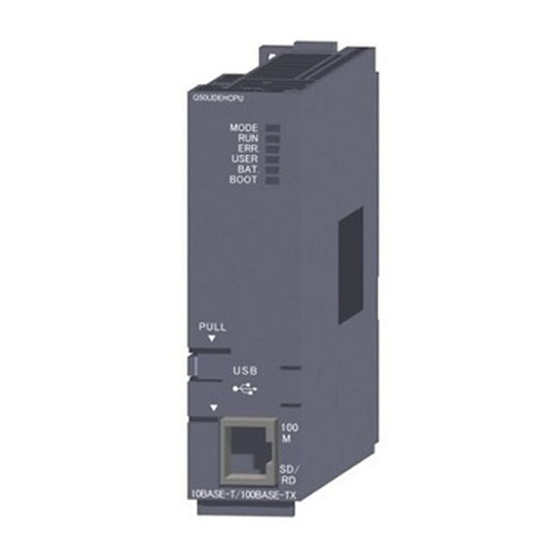
Page 130: Part Names And Functions
4 SET-UP AND PROCEDURE BEFORE OPERATION MELSEC-Q 4.3 Part Names and Functions This section indicates the part names of the Web server module. [When LED cover is closed] [When LED cover is opened] 4 - 6 4 - 6... - Page 131 4 SET-UP AND PROCEDURE BEFORE OPERATION MELSEC-Q Name Description LED Display Refer to (1) LED display. 10BASE-T/ Used for connecting Web server module to 10BASE-T/100BASE-TX. 100BASE-TX interface (Web server module recognizes 10BASE-T/100BASE-TX according to the external connector (RJ45) device.) (Refer to Section 2.2.) RS-232 interface connector Used for connecting Web server module to RS-232.
-
Page 132: Cable Connection
4 SET-UP AND PROCEDURE BEFORE OPERATION MELSEC-Q 4.4 Cable Connection This section explains how to connect cables to the Web server module. To realize a reliable system and fully utilize the Web server module functions, wiring resistant to external noise is required. Ground the RS-232 Cable shield at only one point. -
Page 133: 10Base-T/100Base-Tx Connection
4 SET-UP AND PROCEDURE BEFORE OPERATION MELSEC-Q 4.4.1 10BASE-T/100BASE-TX connection This section provides connection examples for use of the 10BASE-T/100BASE-TX interface of the Web server module. (1) In the case of LAN connection Web server module Intranet Twisted pair cable (straight) (2) In the case of Internet connection using ADSL modem ADSL modem... -
Page 134: Connection
4 SET-UP AND PROCEDURE BEFORE OPERATION MELSEC-Q 4.4.2 RS-232 connection This section provides a connection example for use of the RS-232 interface of the Web server module. In the case of Internet connection using analog modem Analog modem RS-232 LINE Web server module Telephone... -
Page 135: Network Setting Of Personal Computer For One-To-One Connection
4 SET-UP AND PROCEDURE BEFORE OPERATION MELSEC-Q 4.5 Network Setting of Personal Computer for One-to-one Connection Connect the Web server module with the personal computer on a one-to-one basis, and set the Web server module from the Web browser on the personal computer. This section explains the network setting of the personal computer when the Web server module and personal computer are connected on a one-to-one basis. - Page 136 4 SET-UP AND PROCEDURE BEFORE OPERATION MELSEC-Q (b) Make the network setting of the personal computer on the "TCP/IP Properties" screen. ® ® (Example 1) For Microsoft Windows 7 Professional Operating system [Control Panel] "View network status and tasks" in "Network and Internet"...
-
Page 137
4 SET-UP AND PROCEDURE BEFORE OPERATION MELSEC-Q ® ® (Example 2) For Microsoft Windows XP Professional operating system [Control Panel] "Network and Internet Connections" "Network Connections" "Local Area Connection"
tab Properties button Select "Internet Protocol (TCP/IP)". - Page 138 4 SET-UP AND PROCEDURE BEFORE OPERATION MELSEC-Q (3) Web browser setting Local area network [LAN] setting In Local Area Network [LAN] Settings of the Web browser, make setting so that the proxy server is not used at the local address. ®...
-
Page 139
4 SET-UP AND PROCEDURE BEFORE OPERATION MELSEC-Q ® ® (Example 3) For Microsoft Windows 98 operating system and Internet ® Explorer [Tools] [Internet Options]
tab LAN Settings... "Local Area Network [LAN] Settings" screen 4 - 15 4 - 15... - Page 140 4 SET-UP AND PROCEDURE BEFORE OPERATION MELSEC-Q Temporary Internet files settings/delete Select any other than "Never" for "Check for newer versions of stored pages" in the temporary Internet files settings of the Web browser. If "Never" is set, the old screen (the one saved in the temporary Internet files) is displayed unchanged when the file is read from the Edit screen, etc.
-
Page 141
4 SET-UP AND PROCEDURE BEFORE OPERATION MELSEC-Q ® ® (Example 2) For Microsoft Windows XP Professional operating ® system and Internet Explorer [Internet Options]
tab [Tools] Settings in "Temporary Internet files" "Settings" screen ® ® (Example 3) For Microsoft Windows 98 operating system and ®... - Page 142 4 SET-UP AND PROCEDURE BEFORE OPERATION MELSEC-Q The old screen (the one saved in the temporary Internet files) may be displayed unchanged if the file is read from the User HTML, Edit screen, etc. In that case, delete the temporary Internet files (cache) of the Web browser and read the file again.
-
Page 143
4 SET-UP AND PROCEDURE BEFORE OPERATION MELSEC-Q ® ® (Example 2) For Microsoft Windows XP Professional operating ® system and Internet Explorer [Tools] [Internet Options]
tab Delete Files in "Temporary Internet files" "Delete Files" screen When using Java VM (Oracle Corporation) for -
Page 144
4 SET-UP AND PROCEDURE BEFORE OPERATION MELSEC-Q ® ® (Example 3) For Microsoft Windows 98 operating system and ® Internet Explorer [Tools] [Internet Options]
tab Temporary Internet Files Delete Files... "Delete Files" screen When using Java VM (Oracle Corporation) for - Page 145 4 SET-UP AND PROCEDURE BEFORE OPERATION MELSEC-Q Security level setting In the security level setting of the Web browser, set the security level of the Internet and Intranet zones to "Default Level". Make the setting in the "Internet Option" screen. ®...
-
Page 146
4 SET-UP AND PROCEDURE BEFORE OPERATION MELSEC-Q ® ® (Example 3) For Microsoft Windows 98 operating system and Internet ® Explorer [Tools] [Internet Options]
tab Detailed setting Reset the advanced settings of the Web browser to default (the settings when the product is installed for the first time). -
Page 147
4 SET-UP AND PROCEDURE BEFORE OPERATION MELSEC-Q ® ® (Example 2) For Microsoft Windows XP Professional operating system ® and Internet Explorer [Tools] [Internet Options]
tab ® To use Microsoft VM, clear the "JIT compiler for virtual machine enabled (requires restart)"... -
Page 148
4 SET-UP AND PROCEDURE BEFORE OPERATION MELSEC-Q Cookies setting In the Advanced Privacy Settings window, specify how to handle cookies. ® ® (Example 1) For Microsoft Windows 7 Professional operating system and ® Internet Explorer [Tools] [Internet Options]
tab Advanced button ... - Page 149 4 SET-UP AND PROCEDURE BEFORE OPERATION MELSEC-Q (4) Accessing the Web server module from the personal computer Start the Web browser from the personal computer and enter the address of the Web server module as indicated below. [http://192.168.3.3/] As the user authentication screen ("Enter Network password " screen) appears when accessing the Web server module, enter the following.
- Page 150 4 SET-UP AND PROCEDURE BEFORE OPERATION MELSEC-Q (5) Accessing the host CPU of the Web server module Display the "Device monitor" screen Within the Monitor screen. [Monitor screen] "Device monitor" Access the host CPU of the Web server module and confirm that the following input signals (X) are on.
-
Page 151: Setting From Web Browser
4 SET-UP AND PROCEDURE BEFORE OPERATION MELSEC-Q 4.6 Setting from Web Browser It is required to make setting from the Web browser to use the Web server module. The Web server module has the standard screen for setting/monitoring the Web server module. - Page 152 4 SET-UP AND PROCEDURE BEFORE OPERATION MELSEC-Q (1) Monitor screen [Menu items] Item Description Reference Section Device monitor Monitors device values. Tag data monitor Monitors tag data. Logging monitor Monitors logging data. Section 6.2 Event history monitor Monitors event historical data. PLC diagnostics monitor Monitors programmable controller CPU operation status.
- Page 153 4 SET-UP AND PROCEDURE BEFORE OPERATION MELSEC-Q (2) Administrative menu Screen name Screen name will be displayed. Location Menu Shows the location of Select a setting screen. the currently displayed screen. Click on the button to move to the Administrative menu top page or the default top page.
-
Page 154: Common Operations For The Standard Screen
4 SET-UP AND PROCEDURE BEFORE OPERATION MELSEC-Q 4.6.2 Common operations for the standard screen This section explains the common operations for the standard screen. Refer to the corresponding sections for the monitor and set screens. (1) Standard screen displaying procedure Start the Web browser from the personal computer and enter the Web server module's address. - Page 155 4 SET-UP AND PROCEDURE BEFORE OPERATION MELSEC-Q (2) Saving the Administrative menu settings On setting screens of the Administrative menu, change the settings and then click on the "Save" button. Clicking on the "Save" button writes the new settings over the set data of the Web server module.
- Page 156 4 SET-UP AND PROCEDURE BEFORE OPERATION MELSEC-Q Update by powering off the Web server module and on, or resetting the CPU module Powering the programmable controller off and then on or resetting the CPU module updates the settings made on the setting screen on the Web server module.
-
Page 157: System Setting
4 SET-UP AND PROCEDURE BEFORE OPERATION MELSEC-Q 4.6.3 System setting [Setting Purpose] Makes the initial setting required for the Web server module to connect to the network. Be sure to make this setting to use the Web server module. [Start Procedure] [Administrative menu] "System setting"... - Page 158 4 SET-UP AND PROCEDURE BEFORE OPERATION MELSEC-Q (1) Network type setting Set the connection method of the Web server module to the network. Select the connection method of the Web server module to the network. Item Description Connecting through LAN Select this item when connecting through LAN or the router.
- Page 159 4 SET-UP AND PROCEDURE BEFORE OPERATION MELSEC-Q When "Use the following DNS server address." has been selected, set the IP address of the DNS server in decimal number. Up to two DNS servers can be registered for a web server module. When obtaining the IP address from the domain name, retrieve it from the DNS server of the DNS server address 1.
- Page 160 4 SET-UP AND PROCEDURE BEFORE OPERATION MELSEC-Q When "Use the following FTP port number." is selected, set the FTP port number in decimal. 1024 to 65535: FTP port number Consult the network administrator (person who plans the network and manages the IP address) before setting the FTP port number.
- Page 161 4 SET-UP AND PROCEDURE BEFORE OPERATION MELSEC-Q (8) Automatic network connection setting at start-up Set whether automatic network connection will be made or not at a start. Item Description No connection to network Network connection/disconnection processing is required when at start-up. continuous connection is not available.
-
Page 162: Dial-Up Setting
4 SET-UP AND PROCEDURE BEFORE OPERATION MELSEC-Q 4.6.4 Dial-up setting [Setting Purpose] Make the setting required for the Web server module to connect to the Internet. [Start Procedure] [Administrative menu] " Dial-up setting" [Setting Screen] [Setting Item] Item Description Connection method Sets the connecting method of the Web server module. - Page 163 4 SET-UP AND PROCEDURE BEFORE OPERATION MELSEC-Q (1) Connection method Set the connection method of the Web server module. Select the method of connecting the Web server module to the Internet from Modem or ADSL. Make the settings of (2) to (6) according to the selected connection method. The items unnecessary for the selected connection method are disabled.
- Page 164 4 SET-UP AND PROCEDURE BEFORE OPERATION MELSEC-Q (5) Retry Set the items related to network connection retries. Number of retries (0 to 255 times) Set the number of connection request retries when connection to the network fails. Change access point automatically. Make this setting when registering more than one access point.
- Page 165 4 SET-UP AND PROCEDURE BEFORE OPERATION MELSEC-Q CALL function Set whether the CALL function will be enabled or not. (Disable/Enable) When using the CALL function, make a call from the telephone to the Web server module side modem. This allows the Web server module to connect to the network.
- Page 166 4 SET-UP AND PROCEDURE BEFORE OPERATION MELSEC-Q REMARKS The following table indicates the setting necessity of the dial-up setting for the network connection method. Network connection method Item Modem ADSL Connection method Connection account Access point Dial method Retry Communication speed Calling timeout Dial pause time Modem attribute...
-
Page 167: Account Setting
4 SET-UP AND PROCEDURE BEFORE OPERATION MELSEC-Q 4.6.5 Account setting [Setting Purpose] Set the user authentication account that will be confirmed when accessing the Web server module. When accessing the Web server module, the following user authentication screen ("Enter Network password" screen) appears. Enter the account set in the Account setting. - Page 168 4 SET-UP AND PROCEDURE BEFORE OPERATION MELSEC-Q (1) Account setting Make account setting. Up to 16 accounts can be set. Prior to shipment, the following default account is registered for the Web server module as the account setting No. 1. (The default account can be edited.) ...
- Page 169 4 SET-UP AND PROCEDURE BEFORE OPERATION MELSEC-Q (2) Edit screen Register the account. [Setting screen] [Setting item] Item Description User name Sets the user name. (1 to 20 characters) Password Sets the password. (8 to 14 characters) Confirm password Enters the password again. Access authority Selects device write/tag component write/administrator authority.
- Page 170 4 SET-UP AND PROCEDURE BEFORE OPERATION MELSEC-Q Initial screen The initial screen can be set to be displayed when the address "http://IP address" of the Web server module is specified from the Web browser. Make this setting when it is desired to change the top page of the standard screen (refer to Section 4.6.1) to a user-specified screen.
- Page 171 4 SET-UP AND PROCEDURE BEFORE OPERATION MELSEC-Q (3) Security precautions for the Web server module The Web server module supports the basic authentication by the user name and password (account setting) and the IP filter function (Refer to Section 4.6.6), however, they cannot prevent illegal access from the outside completely.
-
Page 172: Ip Filter Setting
4 SET-UP AND PROCEDURE BEFORE OPERATION MELSEC-Q 4.6.6 IP filter setting [Setting Purpose] The IP filter function identifies the IP address of the access source to restrict access to the Web server module. The IP filter function applies to all access of the Web, FTP, etc. to the Web server module. - Page 173 4 SET-UP AND PROCEDURE BEFORE OPERATION MELSEC-Q Mask bit length Set the valid bit length of the set IP address. (Setting range: 1 to 32) Action Set the action (pass/block) to be taken when the received IP packet meets the filter setting condition. (Example) When the IP address is set to "210.99.88.00", the action becomes valid in the following IP address range.
- Page 174 4 SET-UP AND PROCEDURE BEFORE OPERATION MELSEC-Q (4) IP filter setting example When making the IP filter setting, take the precautions given in (5) of this section. Internet connection A setting example of enabling access from a mobile personal computer and office is given below.
- Page 175 4 SET-UP AND PROCEDURE BEFORE OPERATION MELSEC-Q IP filter setting (5) Precautions for IP filter setting When using a mail server, FTP server, DHCP server, DNS server or router, do not set the IP addresses of these devices to "Block". If it is blocked, communication with the corresponding device is disabled.
-
Page 176: Access Target Cpu Setting
4 SET-UP AND PROCEDURE BEFORE OPERATION MELSEC-Q 4.6.7 Access target CPU setting [Setting Purpose] Sets the connection path to the access target CPU. When performing device monitor, tag setting, etc., specify the CPU name set in this setting. [Start Procedure] [Administrative menu] "Access target CPU setting"... - Page 177 4 SET-UP AND PROCEDURE BEFORE OPERATION MELSEC-Q (2) Edit screen Register the access target CPU. [Setting screen] [Setting item] Item Description CPU name Sets the access target CPU name. (Within 16 characters) PLC series Sets the programmable controller series of the access target CPU. Multiple CPU specification Sets the CPU No.
- Page 178 4 SET-UP AND PROCEDURE BEFORE OPERATION MELSEC-Q Other station specification Set whether other station is specified or not. For details on accessible routes, refer to Appendix 2 (2). No specification Select this setting when making access to the host CPU. Other station (Single network) To access a CPU on another station in the following network configuration, select a single network.
- Page 179 4 SET-UP AND PROCEDURE BEFORE OPERATION MELSEC-Q Network communication route, Different network communication route Set the network type, network No., start I/O address and station No. to be accessed. The setting items change depending on the set network. POINT (1) For access to the other station CPU, the routing parameters must also be set in addition to this setting.
- Page 180 4 SET-UP AND PROCEDURE BEFORE OPERATION MELSEC-Q (3) Precautions for access target CPU setting Web server module requires preparatory time to communicate with the access target CPU when the "Update" button on the Setting update screen is clicked, the programmable controller is powered off and then on, or the CPU module is reset.
-
Page 181: Intelligent Function Module Switch Setting
4 SET-UP AND PROCEDURE BEFORE OPERATION MELSEC-Q 4.7 Intelligent Function Module Switch Setting [Setting Purpose] Set the mode, default operation, battery error detection, logging monitor, response monitoring time, and access log (HTTP login) registration inhibition for Web server module on the "Intelligent function module switch setting" screen. [Start Procedure] [GX Developer]... - Page 182 4 SET-UP AND PROCEDURE BEFORE OPERATION MELSEC-Q (2) Default operation setting/Battery error detection setting/Logging monitor setting/Access log (HTTP login) registration inhibit setting (switch 2) Select the default operation setting/battery error detection setting/logging monitor setting/access log (HTTP login) registration inhibit setting for the Web server module.
- Page 183 4 SET-UP AND PROCEDURE BEFORE OPERATION MELSEC-Q Battery error detection setting (bit 2) This setting is provided to determine whether battery error detection is enabled or not while the Web server module is operating without battery. (Refer to Section 4.11.) 0 : Detects battery error.
- Page 184 4 SET-UP AND PROCEDURE BEFORE OPERATION MELSEC-Q [Operation procedure] Make setting from the I/O assignment setting screen of GX Developer. (a) I/O assignment setting screen Set the following to the slot mounted with the Web server module. Type : Select "Intelli.". Model name : Enter the model name of the Web server module.
-
Page 185: Self-Diagnostics Function
4 SET-UP AND PROCEDURE BEFORE OPERATION MELSEC-Q 4.8 Self-diagnostics Function This section explains the self-diagnostics function designed to check the communication function and hardware of the Web server module 4.8.1 CH1 self-loopback test Conduct a self-loopback test to check hardware including the communication function of the CH1 (10BASE-T/100BASE-TX interface) of the Web server module. -
Page 186: Ch2 Self-Loopback Test
4 SET-UP AND PROCEDURE BEFORE OPERATION MELSEC-Q 4.8.2 CH2 self-loopback test Conduct a self-loopback test to check a hardware including the communication function of the CH2 (RS-232 interface) of the Web server module. (1) Operation mode setting for Web server module In "Switch setting for I/O and intelligent function module"... -
Page 187: Hardware Test
4 SET-UP AND PROCEDURE BEFORE OPERATION MELSEC-Q 4.8.3 Hardware test Conduct a test related to the ROM/RAM/switch setting of the Web server module. (1) Operation mode setting for Web server module In "Switch setting for I/O and intelligent function module" of GX Developer, set the mode to "Hardware test". -
Page 188: Setting/Removal Of Compactflash Card And Precautions For Use
4 SET-UP AND PROCEDURE BEFORE OPERATION MELSEC-Q 4.9 Setting/Removal of CompactFlash Card and Precautions for Use This section describes how to set or remove the CompactFlash card and precautions for use. 4.9.1 Precautions for using CompactFlash card This section explains precautions for use of the CompactFlash card. (1) Precautions for available CompactFlash cards Use a CompactFlash card listed in Section 2.4. - Page 189 4 SET-UP AND PROCEDURE BEFORE OPERATION MELSEC-Q (5) Precautions for formatting CompactFlash card (a) Use the formatting function of the Web server module to format the CompactFlash card. (Refer to Section 6.10.2.) (b) Do not format the CompactFlash card on Windows ®...
-
Page 190: Setting/Removal Of Compactflash Card
4 SET-UP AND PROCEDURE BEFORE OPERATION MELSEC-Q 4.9.2 Setting/Removal of CompactFlash card This section explains the setting/removal of the CompactFlash card. [Setting the CompactFlash Card] Setting of CompactFlash card Insert CompactFlash card. (Refer to Section (3)) Is power ON? Turn programmable controller ON. Check if CompactFlash card has been set in Web server module securely. - Page 191 4 SET-UP AND PROCEDURE BEFORE OPERATION MELSEC-Q [Removing or Replacing the CompactFlash Card] Before removing or replacing the CompactFlash card, be sure to stop the file access by the following procedures. Removal/Replacement of CompactFlash card Is power ON? Turn programmable controller ON. Stop file access and disable read from/write to CompactFlash card.
- Page 192 4 SET-UP AND PROCEDURE BEFORE OPERATION MELSEC-Q File access stop request (Y2) (Operating) (Stopped) File access status (X2) CompactFlash card setting status (X1) (2) Canceling file access stop status Cancel the file access stop status. Turn File access stop cancel request (Y3) from OFF to ON. Confirm that the file access stop status has been cancelled.
- Page 193 4 SET-UP AND PROCEDURE BEFORE OPERATION MELSEC-Q LED cover Pawl position EJECT button Insert in Orientation of this direction CompactFlash card CompactFlash card CompactFlash card slot Lower the LED cover until it clicks. When the CompactFlash card is set, the CompactFlash card slot cover cannot be attached to the Web server module.
- Page 194 4 SET-UP AND PROCEDURE BEFORE OPERATION MELSEC-Q 2) When removing the CompactFlash card from the Web server module, press the EJECT button to push the CompactFlash card out. Attach the CompactFlash card slot cover and close the LED cover. Attach the CompactFlash card slot cover. When the CompactFlash card is not set, attach the CompactFlash card slot cover.
-
Page 195: Mounting And Replacement Of Battery
4 SET-UP AND PROCEDURE BEFORE OPERATION MELSEC-Q 4.10 Mounting and Replacement of Battery This section explains the mounting and replacement of the battery. 4.10.1 Battery specifications The following table provides the specifications of the battery for the Web server module. Model Q6BAT Item... -
Page 196: Mounting Of Battery
4 SET-UP AND PROCEDURE BEFORE OPERATION MELSEC-Q 4.10.2 Mounting of battery At shipment, the battery connector is not mounted to the battery of the Web server module. Before using the Web server module, connect the battery connector. Open the cover at the bottom of the Web server module. Confirm that the battery has been mounted correctly. -
Page 197: Battery Replacement
4 SET-UP AND PROCEDURE BEFORE OPERATION MELSEC-Q 4.10.3 Battery replacement This section explains the battery replacement of the Web server module. The battery of the Web server module is used for file protection. It is required to replace the battery when the voltage of the Web server module battery has dropped. - Page 198 4 SET-UP AND PROCEDURE BEFORE OPERATION MELSEC-Q (2) Web server module battery (Q6BAT) life The following table shows the Web server module battery life. Battery life Energization Guaranteed value Actual service value Guaranteed time after battery error time ratio (reference value) occurrence 26,000 hour 43,800 hour...
- Page 199 4 SET-UP AND PROCEDURE BEFORE OPERATION MELSEC-Q (3) Web server module battery replacement When the Web server module battery has been exhausted, replace the battery with a new one according to the procedure shown below. The programmable controller must be powered on for 10 minutes or more before removing the battery.
-
Page 200: Operation Without Battery Being Mounted
4 SET-UP AND PROCEDURE BEFORE OPERATION MELSEC-Q 4.11 Operation without Battery Being Mounted This section explains the operation without the battery being mounted. (1) Shut-down operation required when powering off during no battery operation If the file protection battery is not mounted on the Web server module, make sure to perform shut-down operation at power-off of the programmable controller. -
Page 201: Removing Battery For Storage
4 SET-UP AND PROCEDURE BEFORE OPERATION MELSEC-Q 4.12 Removing Battery for Storage When storing the Web server module with no battery mounted, make sure to perform shut-down operation, then power off the programmable controller, and remove the battery. Important Failure to observe the following procedure may cause erasure of logging data during processing, corruption of data in the standard ROM drive/CompactFlash card during access, or a file system fault. -
Page 202: Returning The Web Server Module To The Default Setting
4 SET-UP AND PROCEDURE BEFORE OPERATION MELSEC-Q 4.13 Returning the Web Server Module to the Default Setting The Web server module stores and manages the setting information, logging data, user HTML, event history, etc. as files in the standard ROM. The operation described in this section initializes the files stored in the Web server module to return the Web server module to the default setting. -
Page 203: Connecting Web Server Module To Network
5 CONNECTING WEB SERVER MODULE TO NETWORK MELSEC-Q 5 CONNECTING WEB SERVER MODULE TO NETWORK This chapter explains procedures for connecting the Web server module to the network by LAN/dial-up connection and procedures for connecting and disconnecting it to/from the network for non-continuous connection. 5.1 Network Connection through LAN This section explains the case where the Web server module is connected to the LAN- connected network. - Page 204 5 CONNECTING WEB SERVER MODULE TO NETWORK MELSEC-Q (1) Network setting of Web server module Make setting to connect the Web server module to the network. From the Administrative menu, set as follows (For other than the following settings, the default values will be used.): [Administrative menu] "System setting"...
- Page 205 5 CONNECTING WEB SERVER MODULE TO NETWORK MELSEC-Q When connection to the network fails, connection error (X19) turns on and an error code is stored into the connection error code area (buffer memory: 30). Take corrective measures according to the troubleshooting. POINT In the network connection status area (buffer memory: 28 to 69), the current network connection status of the Web server module can be confirmed.
-
Page 206: Access Procedure When Obtaining Ip Address From Dhcp Server
5 CONNECTING WEB SERVER MODULE TO NETWORK MELSEC-Q 5.1.2 Access procedure when obtaining IP address from DHCP server The following shows the procedure for access from the external device to the programmable controller CPU when an IP address for the Web server module is obtained from the DHCP server. - Page 207 5 CONNECTING WEB SERVER MODULE TO NETWORK MELSEC-Q (1) Network setting of Web server module Make setting to connect the Web server module to the network. From the Administrative menu, set as follows (For other than the following settings, the default values will be used.): [Administrative menu] "System setting"...
- Page 208 5 CONNECTING WEB SERVER MODULE TO NETWORK MELSEC-Q POINT After changing the setting, make sure to click on the "Save" button. The settings are updated when the "Update" button on the Setting update screen is clicked, the programmable controller is powered off and then on, or the CPU module is reset.
- Page 209 5 CONNECTING WEB SERVER MODULE TO NETWORK MELSEC-Q (3) Receiving the account notification by the personal computer By the address notification setting, the URL of the Web server module is sent by e-mail to the destination e-mail address. (Example) In the case of Microsoft Outlook Express 5.5 (4) Access to Web server module...
-
Page 210: Network Connection By Dial-Up (Modem, Adsl)
5 CONNECTING WEB SERVER MODULE TO NETWORK MELSEC-Q 5.2 Network Connection by Dial-up (Modem, ADSL) This section explains the case where the Web server module is connected to the dial- up-connected network using ADSL. 5.2.1 Access procedure The following shows the procedure for access from the external device to the programmable controller CPU when an ADSL modem is used for connection. - Page 211 5 CONNECTING WEB SERVER MODULE TO NETWORK MELSEC-Q (1) Contract with Internet service provider To connect the Web server module to the Internet, a contract with an Internet service provider is required. Contact the Internet service provider for service details and how to sign up for the service.
- Page 212 5 CONNECTING WEB SERVER MODULE TO NETWORK MELSEC-Q E-mail setting (Refer to Section 6.6.3) Item Set value Enter the e-mail setting of the Web server module. SMTP server name : (example) mailserver@****.****.ne.jp E-mail address (From:) : (example) mailaddress@****.****.ne.jp Send e-mail account setting ...
- Page 213 5 CONNECTING WEB SERVER MODULE TO NETWORK MELSEC-Q (3) Network connection of Web server module Since "Automatic connection to network at start-up." is set in the automatic network connection setting at start-up on the "System setting" screen, the Web server module automatically makes network connection at start-up. Using GX Developer, confirm the following connection status of the Web server module to the network with input signals of the buffer memory and the programmable controller CPU.
- Page 214 5 CONNECTING WEB SERVER MODULE TO NETWORK MELSEC-Q (5) Access to Web server module Start a Web browser on the personal computer and enter the Web server module address obtained by the address notification function. When the user authentication screen is displayed at the time of access to the Web server module, enter the account.
-
Page 215: Operation For Returning To One-To-One Connection
5 CONNECTING WEB SERVER MODULE TO NETWORK MELSEC-Q 5.3 Operation for Returning to One-to-one Connection This section explains the operation for returning to one-to-one connection. If connection of the Web server module to the network cannot be made or if the network setting is to be changed, it is required to make one-to-one connection and perform setting with the Web browser. - Page 216 5 CONNECTING WEB SERVER MODULE TO NETWORK MELSEC-Q After writing the PLC parameters to the programmable controller CPU, power the programmable controller off and then on or reset the CPU module. The settings of the Web server module are as follows. System setting ...
-
Page 217: Network Connection/Disconnection Procedures For Non-Continuous Connection
5 CONNECTING WEB SERVER MODULE TO NETWORK MELSEC-Q 5.4 Network connection/disconnection procedures for non-continuous connection This section explains the network connection and disconnection methods and their combinations and the procedures for connecting to and disconnecting from the network with sequence programs. 5.4.1 Network connection and disconnection methods and their combinations This section provides the network connection and disconnection methods and their combinations. - Page 218 5 CONNECTING WEB SERVER MODULE TO NETWORK MELSEC-Q Disconnection using line disconnection part When a button is clicked in a line disconnection part, the Web server module disconnects from the network. (Refer to Section 7.4.3.) Disconnection using Disconnect function (Only when modem is connected) When the "Disconnect function"...
- Page 219 5 CONNECTING WEB SERVER MODULE TO NETWORK MELSEC-Q (3) Combinations of network connection and disconnection methods Combinations of the network connection and disconnection methods are indicated below. Disconnection Disconnection Disconnection Disconnection method using Disconnect using using line Automatic function Connection sequence disconnection disconnection...
-
Page 220: Network Connection/Disconnection Processing Using Sequence Program
5 CONNECTING WEB SERVER MODULE TO NETWORK MELSEC-Q 5.4.2 Network Connection/Disconnection Processing Using Sequence Program The Web server module must be connected to the network for access from the external device. With the Web server module connected to the network, access from the external device by Web or FTP is available. - Page 221 5 CONNECTING WEB SERVER MODULE TO NETWORK MELSEC-Q (2) Program example This section explains programs for connection/disconnection using sequence programs. Program execution environment Mount the Web server module on Slot "0" of the main base. Connect the Web server module and the personal computer with a crossing cable.
- Page 222 5 CONNECTING WEB SERVER MODULE TO NETWORK MELSEC-Q Program example 5 - 20 5 - 20...
- Page 223 5 CONNECTING WEB SERVER MODULE TO NETWORK MELSEC-Q 5 - 21 5 - 21...
-
Page 224: Functions
6 FUNCTIONS MELSEC-Q 6 FUNCTIONS This chapter explains the functions of the Web server module. 6.1 Function List of Web Server Module The following is the function list of the Web server module. Reference Function Description Section Section Device monitor Monitors device values. -
Page 225: Monitor Function
6 FUNCTIONS MELSEC-Q 6.2 Monitor Function 6.2.1 Device monitor [Setting Purpose] This monitoring function is used to specify one type of device to execute batch monitor. Users with the device write authority can write data in word unit or operate ON/OFF data in bit unit. - Page 226 6 FUNCTIONS MELSEC-Q CPU name Set the access target CPU. Select the CPU name set in the access target CPU setting. (Refer to Section 4.6.7 for the access target CPU setting.) The CPU name drop-down list displays the setting No. and CPU names of the access target CPU setting.
- Page 227 6 FUNCTIONS MELSEC-Q (2) Device test Executing device test turns the bit device of the programmable controller CPU on/off forcibly or changes the current value of the word device. Only users with the device write authority are allowed to conduct this test. Refer to Section 4.6.5 for the user authority.
- Page 228 6 FUNCTIONS MELSEC-Q Setting value When setting the data type as a 16 bit integer or 32 bit integer, set a new value in accordance with the DEC/HEX input form. When setting the data type in bit, set ON/OFF. POINT (1) The device test may affect the control of the programmable controller.
-
Page 229: Tag Data Monitor
6 FUNCTIONS MELSEC-Q 6.2.2 Tag data monitor [Setting Purpose] This monitoring function is used to monitor the tag data, which have been collected by the Web server module with the tag function, in tag unit. Refer to Section 6.3 for the tag function. By conducting a tag component test, users with the tag component write authority can write tag data in the component unit. - Page 230 6 FUNCTIONS MELSEC-Q Tag name Set the tag data to perform tag data monitor. Select the tag name set in the tag setting. (Refer to Section 6.3.3 for the tag setting.) The Tag name drop-down list displays the setting No. and tag names of the tag setting.
- Page 231 6 FUNCTIONS MELSEC-Q Tag name The tag name to perform the tag component test is displayed. Component name Select the component name set in "Component setting" of the tag setting. (Refer to Section 6.3.3 for "Component setting" of the tag setting.) The Component name drop-down list displays the setting No.
- Page 232 6 FUNCTIONS MELSEC-Q POINT (1) The tag component test may affect the control of the programmable controller. Ensure safety before execution. (2) A user without the tag component write authority is not allowed to conduct the tag component test. When the tag component test is attempted, the following screen appears. (3) When Device write disable request (YA) has been set to "Disable", the tag component test is not available.
-
Page 233: Logging Monitor
6 FUNCTIONS MELSEC-Q 6.2.3 Logging monitor [Setting Purpose] This monitoring function displays the logging data that have been collected by the Web server module with the logging function. Refer to Section 6.4 for the logging function. The display form is selectable from List or Graph. The contents of the logging file located under /ROM/WWW/LOGGING/ or /CF/LOGGING are displayed. - Page 234 6 FUNCTIONS MELSEC-Q (1) Logging name Set the logging data to perform the logging monitor. Select the tag name set in the logging setting. (Refer to Section 6.4.4 for the logging setting.) The Logging name drop-down list displays the setting No. and tag names of the logging setting.
- Page 235 6 FUNCTIONS MELSEC-Q (5) Graph Logging data are displayed in graph form. Specify the component to be monitored. (Up to four components can be specified.) ( 1) Specify the maximum and minimum values and No. of horizontal grid lines in the graph. ( 1) 1) Specify the maximum value of the graph.
-
Page 236: Event History Monitor
6 FUNCTIONS MELSEC-Q 6.2.4 Event history monitor [Setting Purpose] This monitoring function displays the history of the events occurred in the Web server module and saved with the event monitor function. Refer to Section 6.5 for the event function. RCPU cannot perform the CPU monitor. ("System error" is displayed in the operation status.) [Start Procedure] [Monitor screen]... - Page 237 6 FUNCTIONS MELSEC-Q (2) CPU event The CPU event history is monitored. The contents of /ROM/WWW/EVENT/CPUWATCH.CSV are displayed. Date The date and time when the event occurred/was restored is displayed. (Example) 2002/08/05 08:58:17 Event number The event number of the event occurrence/restoration is displayed. The event number is the No.
- Page 238 6 FUNCTIONS MELSEC-Q Operation status The operation status of the programmable controller CPU in which the event occurred/was restored is displayed. Item Description Normal STOP The programmable controller CPU is stopped with no error. Normal RUN The programmable controller CPU is running with no error. PAUSE The programmable controller CPU is pausing.
- Page 239 6 FUNCTIONS MELSEC-Q Event number The event number of the event occurrence/restoration is displayed. The event number is the No. set in "Tag event setting" of the event setting. Status The occurrence/restoration of the event is displayed. Tag name The name of the tag in which the event occurred/was restored is displayed.
- Page 240 6 FUNCTIONS MELSEC-Q (4) Time/Interval event The time/interval event history is monitored. The contents of /ROM/WWW/EVENT/TIMWATCH.CSV are displayed. Date The date and time when the event occurred is displayed. (Example) 2002/08/05 08:58:17 Event number The event number of the event occurrence is displayed. The event number is the No.
-
Page 241: Plc Diagnostics Monitor
6 FUNCTIONS MELSEC-Q 6.2.5 PLC diagnostics monitor [Setting Purpose] This monitoring function is used to monitor the operating status/error information of the programmable controller CPU. RCPU does not support the PLC diagnostics monitor function. [Start Procedure] [Monitor screen] "PLC diagnostics monitor" [Setting screen] [Setting Item] Item... - Page 242 6 FUNCTIONS MELSEC-Q (1) CPU name Set the access target CPU. The C Controller module cannot be monitored. To monitor the operation status and error information of the C Controller module, use the C Controller setting utility. Select the CPU name set in the access target CPU setting. (Refer to Section 4.6.7 for the access target CPU setting.) The CPU name drop-down list displays the setting No.
-
Page 243: Self-Diagnostics Monitor
6 FUNCTIONS MELSEC-Q 6.2.6 Self-diagnostics monitor [Setting Purpose] Self-diagnostics monitor monitors the LED status and error status of the Web server module. [Start Procedure] [Monitor screen] "Self-diagnostics monitor" [Setting Screen] [Setting Item] Item Description LED status Displays the LED status of the Web server module. Error status Displays the latest error code. - Page 244 6 FUNCTIONS MELSEC-Q (1) LED status The LED status (RUN LED, ERR. LED) of the Web server module is displayed. Refer to Section 4.3 (1) for the LED indications. (2) Error status The status of the current error area (address: 140 to 145) of the buffer memory is displayed.
-
Page 245: Precautions For Using Monitor Function
6 FUNCTIONS MELSEC-Q 6.2.7 Precautions for using monitor function This section explains the precautions for using the monitor function. (1) Precautions for displaying the monitor screen Since the monitor screens use the Java applet, Java VM is required for the Web browser to execute the applet. - Page 246 6 FUNCTIONS MELSEC-Q ® ® (Example 2) For Microsoft Windows XP Professional operating system [Start] → [Control Panel] → [Performance and Maintenance] → [Power Options] → "Power Options Properties" screen →< Power Schemes> tab (e) Temporary Internet files settings/delete Select any other than "Never" for "Check for newer versions of stored pages"...
-
Page 247
6 FUNCTIONS MELSEC-Q ® ® (Example 2) For Microsoft Windows XP Professional operating ® system and Internet Explorer [Tools] [Internet Options]
tab Settings in "Temporary Internet files" "Settings" screen ® ® (Example 3) For Microsoft Windows 98 operating system and ®... - Page 248 6 FUNCTIONS MELSEC-Q The old screen (the one saved in the temporary Internet files) may be displayed unchanged if the file is read from the User HTML, Edit screen, etc. In that case, delete the temporary Internet files (cache) of the Web browser and read the file again.
-
Page 249
6 FUNCTIONS MELSEC-Q ® ® (Example 2) For Microsoft Windows XP Professional operating ® system and Internet Explorer [Tools] [Internet Options]
tab Delete Files in "Temporary Internet files" "Delete Files" screen When using Java VM (Oracle Corporation) for -
Page 250
6 FUNCTIONS MELSEC-Q ® ® (Example 3) For Microsoft Windows 98 operating system and ® Internet Explorer [Tools] [Internet Options]
tab Temporary Internet Files Delete Files... "Delete Files" screen When using Java VM (Oracle Corporation) for - Page 251 6 FUNCTIONS MELSEC-Q Security level setting In the security level setting of the Web browser, set the security level of the Internet and Intranet zones to "Default Level". Make the setting in the "Internet Option" screen. ® ® (Example 1) For Microsoft Windows 7 Professional Operating System ®...
-
Page 252
6 FUNCTIONS MELSEC-Q ® ® (Example 3) For Microsoft Windows 98 operating system and Internet ® Explorer [Tools] [Internet Options]
tab Detailed setting Reset the advanced settings of the Web browser to default (the settings when the product is installed for the first time). Make the setting in the "Internet Options"... -
Page 253
6 FUNCTIONS MELSEC-Q ® ® (Example 2) For Microsoft Windows XP Professional operating system ® and Internet Explorer [Tools] [Internet Options]
tab ® To use Microsoft VM, clear the "JIT compiler for virtual machine enabled (requires restart)" check box. ®... - Page 254 6 FUNCTIONS MELSEC-Q (2) Precautions for executing the device test/tag component test The device test/tag component test may affect the control of the programmable controller CPU. Ensure safety before execution. (Example) When the device test is executed A user without device write/tag component write authority is not allowed to conduct the device test/tag component test.
-
Page 255: Tag Function
6 FUNCTIONS MELSEC-Q 6.3 Tag Function 6.3.1 Tag function The tag function is designed to store a set device data of individual programmable controller CPUs on the network as a tag, and collect those device data in tag unit. (1) Tag A tag is a data table contains a set of data (components) required to access the device data of the programmable controller CPUs on the network. -
Page 256: Setting Procedure For Tag Function
6 FUNCTIONS MELSEC-Q (2) Tag setting Set a tag in the tag setting of the Administrative menu. (Refer to Section 6.3.3) Up to 64 tags can be registered. Up to 64 components can be registered for each tag. Set the communication path to access the programmable controller CPU in the access target CPU setting. -
Page 257: Tag Setting
6 FUNCTIONS MELSEC-Q 6.3.3 Tag setting [Setting Purpose] 1) In the tag setting, set a tag. On the Edit screen (Tag setting), set the tag name, tag collecting interval, etc. 2) In the component setting, set components for each tag. On the Edit screen (Component setting), set the access target CPU, data type, device, etc. - Page 258 6 FUNCTIONS MELSEC-Q (2) Edit screen (Tag setting) Set the tag name, tag collecting interval (Sampling), etc. [Setting screen] [Setting Item] Item Description Sets the tag name. (within 16 characters) Tag name Sets the collecting interval of the tag data. Sampling Sets whether data can be written to the tag or not.
- Page 259 6 FUNCTIONS MELSEC-Q Execute at high speed (Sampling interval: 1 to 600 100ms) Tag data are collected once when the Web server module is started or the setting is updated, and thereafter are collected at the specified interval. Update before logging. ...
- Page 260 6 FUNCTIONS MELSEC-Q (3) Component setting Set components for each tag. Up to 64 components can be registered for each tag. Component setting is registered in order of serial numbers starting from the setting No. 1. Component registration is not valid with any omitted setting. [Setting screen] [Setting Item] Item...
- Page 261 6 FUNCTIONS MELSEC-Q POINT (1) Before making component setting, it is required to make tag setting on the "Edit screen (Tag setting)". (2) If any component has a wrong device number in the component setting, the other component that has a device of the same access target CPU will also result in an error.
- Page 262 6 FUNCTIONS MELSEC-Q Component name (within 16 characters) Set the component name. Refer to Appendix 4 (5) for the characters applicable to the component name. CPU name Set the access target CPU. Selects the CPU name set in the access target CPU setting. (Refer to Section 4.6.7 for the access target CPU setting.) The CPU name drop-down list displays the setting No.
- Page 263 6 FUNCTIONS MELSEC-Q Display form Set the display form of the real number. Decimal/Exponential Set the number of decimal places. (0 to 6) Enabled when the data type is either of the following. Real number type Single word/Double word (After operation, a numeric value below decimal point may be produced.) Operator Set a mathematical operation to be performed for the collected data, or no...
-
Page 264: Logging Function
6 FUNCTIONS MELSEC-Q 6.4 Logging Function 6.4.1 Logging function The logging function stores tag data as a CSV format logging file into standard ROM or CompactFlash card in time series at the user-specified execution timing (by setting timing, start/stop condition). Tag data will be logged. - Page 265 6 FUNCTIONS MELSEC-Q (2) Logging data before and after event occurrence can be stored By setting the occurrence of an event as the start/stop condition of logging, logging data before and after event occurrence can be stored. This enables only necessary data to be stored without the logging data before and after event occurrence being buried in the file.
-
Page 266: Logging File
6 FUNCTIONS MELSEC-Q 6.4.2 Logging file This section explains logging files. (1) Where logging files are saved Logging files are stored into standard ROM or CompactFlash card. When a logging file is created, the directory of the file name set at "File name"... - Page 267 6 FUNCTIONS MELSEC-Q Processing performed when file becomes full Creating new file and saving current file When the currently logging file becomes full, a new file is created. The file that has become full is renamed and saved. (Creation of saved file) Saved files names Saved files names are consecutively numbered with 8 digits...
- Page 268 6 FUNCTIONS MELSEC-Q The number of saved files [When the number of saved files [Saved file name] exceeds the set value. exceeds the above set value] Stop Overwrite "When the number of saved files is '5'" Logging is stopped. LOGNAME.CSV LOGGING LOGNAME The oldest file is deleted and logging...
-
Page 269: Setting Procedure For Logging Function
6 FUNCTIONS MELSEC-Q 6.4.3 Setting procedure for logging function The setting procedure for use of the logging function is indicated below. Start Create a network environment for Web server Refer to module to access the Web server module from a Section 4. -
Page 270: Logging Setting
6 FUNCTIONS MELSEC-Q 6.4.4 Logging setting [Setting Purpose] Make the setting for logging tag data. [Start Procedure] [Administrative menu] "Logging setting" (refer to (1)) Select logging setting No. and click on Edit "Edit screen" (refer to (2)) (1) Logging setting Make logging setting. - Page 271 6 FUNCTIONS MELSEC-Q (2) Edit screen Set the tag to be logged, execution timing, file capacity, etc. [Setting screen] [Setting Item] Item Description Sets the tag to be logged, logging file name, and the location where the logging file will be Logging setting saved.
- Page 272 6 FUNCTIONS MELSEC-Q Tag name Set the tag name to be logged. Select the tag name set in the tag setting. (Refer to Section 6.3.3 for the tag setting.) When using the logging function, it is required to set the tag in advance.
- Page 273 6 FUNCTIONS MELSEC-Q POINT (1) Depending on the setting of the tag sampling interval and logging timing, the data accumulated for up to the time length of the tag sampling interval are logged. (Example) When the tag sampling interval is 10 seconds and the logging interval is 1 second, the tag data of up to 10 seconds earlier is logged.
- Page 274 6 FUNCTIONS MELSEC-Q Start at the specified time. Logging is started at the specified time. Hour: 0 to 23, "Per" Minute: 0 to 59, "Per" (Per minute can be specified only when Per hour is specified) Second: 0 to 59 1 Regardless of this setting, logging is performed when the dedicated instruction LOG is executed.
- Page 275 6 FUNCTIONS MELSEC-Q File capacity As the file capacity, select any of the following. Specification for number of lines (1 to 10000 lines)/for high-speed logging (100 to 10000 lines) Size specification (1 to 512k bytes)/for high-speed logging (10 to 512k bytes) Time specification Day: 1 to 31, "Per"...
- Page 276 6 FUNCTIONS MELSEC-Q Checked When the file is saved, it is attached to e-mail and sent. Refer to Section 6.6.5 for the e-mail transmission by the logging function. E-mail addresses 1 to 3 Select the e-mail addresses set in the "E-mail address (TO:) setting" of the E-mail setting.
- Page 277 6 FUNCTIONS MELSEC-Q REMARKS (1) When the file storage has been set to the standard ROM When the logging file storage has been set to the standard ROM in the logging setting, pay attention to the setting of the free space of the user area in the standard ROM or the number of write times to standard ROM.
-
Page 278: Event Monitor Function
6 FUNCTIONS MELSEC-Q 6.5 Event Monitor Function 6.5.1 Event monitor function The event monitor function monitors the programmable controller CPU status (CPU monitor), tag data (tag monitor) and time (time/interval monitor), and stores the historical data of occurred events into CSV files. The stored files can be displayed in a Web browser or downloaded by FTP operation. - Page 279 6 FUNCTIONS MELSEC-Q (1) Event history file The following conditions can be set as event history conditions, and an event history file is created for each event history condition. CPU event The programmable controller CPU status (system error, RUN, STOP, PAUSE, etc.) set in "CPU event setting"...
-
Page 280: Setting Procedure For Event Monitor Function
6 FUNCTIONS MELSEC-Q (2) When the number of event historical data exceeds the limit In each event history file, the following operation is performed when the number of event historical data set in "Common setting" of the event setting exceeds the limit. -
Page 281: Event Setting
6 FUNCTIONS MELSEC-Q 6.5.3 Event setting [Setting Purpose] 1) In the common setting, set each number of event historical data. 2) In the CPU event setting, make setting to monitor the operation status of the programmable controller CPU. 3) In the tag event setting, make setting to compare the tag data and condition value. 4) In the time/interval event setting, make setting to monitor the time/interval. - Page 282 6 FUNCTIONS MELSEC-Q (1) Common setting Make common setting. [Setting Screen] [Setting Item] Item Description No. of CPU event historical Sets the number of CPU event historical data. data No. of tag event historical Sets the number of tag event historical data. data No.
- Page 283 6 FUNCTIONS MELSEC-Q (2) CPU event setting Make setting to monitor the operation status of the programmable controller CPU. Up to 64 CPU event settings are available. RCPU cannot perform the CPU monitor. [CPU event setting screen] [Setting Item] Item Description Item Selects the CPU event setting No.
- Page 284 6 FUNCTIONS MELSEC-Q [Edit screen] [Setting Item] Item Description CPU name Sets the CPU name. Interval Sets the CPU event interval. Condition Sets the CPU event conditions. Mail setting for event Makes setting when sending e-mail at event occurrence. occurrence Saves the setting.
- Page 285 6 FUNCTIONS MELSEC-Q CPU name Set the CPU name to be monitored. Select the CPU name set in the access target CPU setting. (Refer to Section 4.6.7 for the access target CPU setting.) The CPU name drop-down list displays the setting No. and CPU names of the access target CPU setting.
- Page 286 6 FUNCTIONS MELSEC-Q Disconnect from the network after sending mail. Disable this setting when it is not desired to disconnect the network after sending e-mail at event occurrence. This setting is available when the Web server module is not continuously connected to the network.
- Page 287 6 FUNCTIONS MELSEC-Q (3) Tag event setting Make setting to monitor the tag data compared with the trigger value. Up to 256 tag event settings are available. Tag event monitoring is executed every time the target tag is collected by the Web server module.
- Page 288 6 FUNCTIONS MELSEC-Q [Edit screen] [Setting Item] Item Description Tag name Sets the tag name. Component name Sets the component name. Condition Sets the tag event condition. Trigger value Sets the trigger value. Restoration value Sets the restoration value. Mail setting for event Makes setting when sending e-mail at event occurrence.
- Page 289 6 FUNCTIONS MELSEC-Q Tag name Set the tag name to be monitored. Select the tag name set in the tag setting. (Refer to Section 6.3.3 for the tag setting.) The Tag name drop-down list displays the setting No. and tag names of the tag setting.
- Page 290 6 FUNCTIONS MELSEC-Q Restoration value Set the restoration value to make the event disappear. The restoration value can be set when the condition is >=, >, < or <=. In the following case, the event is restored. Condition Restoration Component = Trigger value Component <>...
- Page 291 6 FUNCTIONS MELSEC-Q (4) Time/Interval event setting Make setting to monitor the time/interval. Up to 16 time/interval event settings are available. [Time/Interval event setting screen] [Setting Item] Item Description Item Selects the time/interval event setting No. to be edited or deleted. Time/Interval Displays the monitoring time/interval.
- Page 292 6 FUNCTIONS MELSEC-Q [Setting Item] Item Description Time/Interval Sets the monitoring time/interval. Mail setting for event Makes setting when sending e-mail at event occurrence. occurrence Saves the setting. Save The settings are updated when the "Update" button on the Setting update screen is clicked, the programmable controller is powered off and then on, or the CPU module is reset.
- Page 293 6 FUNCTIONS MELSEC-Q Attached file Select the file attached to e-mail. (None, Tag data, Logging Data) When attaching tag data, select the tag data set in the tag setting. (Refer to Section 6.3.3 for the tag setting.) When attaching logging data, select the logging data set in the logging setting.
-
Page 294: E-Mail Function
6 FUNCTIONS MELSEC-Q 6.6 E-mail Function This section explains the e-mail function. 6.6.1 E-mail function The e-mail function sends the data (tag data, logging data, user data file), which were collected by the Web server module from the programmable controller CPUs, to a remote external device by e-mail. -
Page 295: E-Mail Transmission By Logging Function
6 FUNCTIONS MELSEC-Q (3) E-mail transmission by logging function E-mails are sent by the Web server module according to the logging setting of the Web browser. An e-mail is sent when a file is saved. A fixed subject, fixed main text and a CSV-format attached file of logging data can be sent. - Page 296 6 FUNCTIONS MELSEC-Q 6.6.2 Setting procedure for e-mail function The following is the setting procedure for use of the e-mail function. (1) Common procedure The common procedure for this function is shown below. Start Create a network environment for Web server module Refer to to access the Web server module from a personal Section 4.
- Page 297 6 FUNCTIONS MELSEC-Q (4) Procedure for sending e-mail by logging function Make the setting on the Logging setting so that an For logging function, refer to e-mail will be sent when a file is saved. Section 6. 4. Completed (5) Procedure for sending e-mail by diagnostics function For details of e-mail sending test, Execute e-mail sending test on the System setting.
- Page 298 6 FUNCTIONS MELSEC-Q 6.6.3 E-mail setting [Setting Purpose] In the e-mail setting, setting required for e-mail transmission is set. [Start Procedure] [Administrative menu] "E-mail setting" [Setting Screen] [Setting Item] Item Description Send e-mail account Sets the account of the Web server module required to send e-mail. setting Option setting Sets the option related to e-mail.
- Page 299 6 FUNCTIONS MELSEC-Q (1) Send e-mail account setting The account of the Web server module required to send e-mail is set. Set the account specified by the Internet service provider and system administrator. Refer to Appendix 4 (2) for the characters applicable to the send e-mail account setting.
- Page 300 6 FUNCTIONS MELSEC-Q (2) Option setting How to authenticate a user when sending e-mail is set. Item Description This server has authentication Check the checkbox to execute authentication when sending e-mail. requirements which have to be met Select "SMTP-Auth" or "POP before SMTP" as the method of authentication. Method of authentication When "POP before SMTP"...
- Page 301 6 FUNCTIONS MELSEC-Q (3) E-mail address (To:) setting Set the e-mail address of the transmission destination. Up to 16 destination e-mail addresses can be registered. Refer to Appendix 4 (2) for the characters applicable to the destination e-mail address. POINT After changing the settings, make sure to click on the "Save"...
- Page 302 6 FUNCTIONS MELSEC-Q 6.6.4 E-mail transmission by programmable controller CPU This section explains the WMSEND instruction used to send e-mail with a sequence program. ZP.WMSEND (S1) (S2) "Un" Subject + Main text Mail server Destination No. Tag/Logging No I/O No. File name.
- Page 303 6 FUNCTIONS MELSEC-Q (1) E-mail transmission by sequence program The following explains the method for sending e-mail by a sequence program. Refer to Section 8.2 for details of the WMSEND instruction. Instruction Create control data in D0 and later. Create sending data in D100 and later. An e-mail will be sent.
- Page 304 6 FUNCTIONS MELSEC-Q (3) Sample program The following is a program in which the Web server module mounted in the position of I/O number X/Y00 to X/Y1F sends e-mail when M20 is turned ON. Main text included, logging data attached, clock data setting required Destination No.
- Page 305 6 FUNCTIONS MELSEC-Q (4) Receiving e-mail by personal computer The e-mail sent by the Web server module is received by the personal computer. The e-mail format used by the Web server module is as follows. Item Description E-mail address (From: ) E-mail address of the Web server module Subject set in the control data of the dedicated instruction (1 to Subject...
- Page 306 6 FUNCTIONS MELSEC-Q 6.6.5 E-mail transmission by logging function When a file is saved, the Web server module sends an e-mail to the destination e-mail address. Refer to Section 6.4 for details of the logging function. (1) Logging setting (Refer to Section 6.4.4) In the Logging setting, set "E-mail delivery: Send a saved file to the following e-mail address."...
- Page 307 6 FUNCTIONS MELSEC-Q The e-mail is received by the personal computer. (Example) In the case of Microsoft Outlook Express 5.5 (3) Precautions for sending e-mail by logging function E-mail transmission requires several to several tens of seconds depending on the network line and data size. When "When the number of saved files exceeds the above set value: Overwrite"...
-
Page 308: E-Mail Transmission By Event Monitor Function
6 FUNCTIONS MELSEC-Q 6.6.6 E-mail transmission by event monitor function Performing CPU monitor, tag monitor and time/interval monitor, the Web server module sends an e-mail to the destination e-mail address when an event occurs. Refer to Section 6.5 for details of the event monitor function. (1) E-mail transmission by CPU event CPU event setting (Refer to Section 6.5.3) In the CPU event setting, set "Send an e-mail when an event occurs."... - Page 309 6 FUNCTIONS MELSEC-Q 1 Subject is as follows. (Example) Control CPU Status STOP 2002/07/24 16:46:23 Status Date CPU name • CPU name The CPU name preset in the Access target CPU setting is displayed. • Status The following table shows the send messages corresponding to the CPU module status.
- Page 310 6 FUNCTIONS MELSEC-Q (2) E-mail transmission by tag event Tag event setting (Refer to Section 6.5.3) In the Tag event setting, set "Send an e-mail when an event occurs." and set the E-mail main text, Attached file and Send to. When a tag event occurs, an e-mail is sent to the destination e-mail address.
- Page 311 6 FUNCTIONS MELSEC-Q 1 Subject is as follows. (Example) 2002/07/25 09:37:12 Production mngmt Product A Date Trigger value Condition Tag name Component name • Tag name The tag name set in the Tag setting is displayed. • Component name The component name set in "Component setting" of the Tag setting is displayed.
- Page 312 6 FUNCTIONS MELSEC-Q (3) E-mail transmission by time/interval event Time/Interval event setting (Refer to Section 6.5.3) In the Time/interval event setting, set "Send an e-mail when an event occurs." and set the E-mail main text, Attached file and Send to. When a time/interval event occurs, an e-mail is sent to the destination e-mail address.
- Page 313 6 FUNCTIONS MELSEC-Q Receiving e-mail by personal computer The e-mail sent by the Web server module is received by the personal computer. The e-mail format used by the Web server module is as follows. Item Description E-mail address (From: ) E-mail address of the Web server module "...
-
Page 314: Ftp Function
6 FUNCTIONS MELSEC-Q 6.7 FTP Function The FTP function is designed to transfer a file between the Web server module and external device. The FTP function has the FTP server function and FTP client function. 6.7.1 FTP server function (1) About FTP server function From the external device (FTP client), the file stored in the Web server module can be read and written. - Page 315 6 FUNCTIONS MELSEC-Q (3) Setting procedure for FTP function Start Make access target CPU setting on the Access target Refer to Section 4. 6. FTP function is available with the setting in CPU setting. Section 4. 6. Login to the Web server module to operate files. Refer to Section (4).
- Page 316 6 FUNCTIONS MELSEC-Q After login to the Web server module, write the user HTML file on the personal computer to the USER directory of the Web server module so that normal file operation using Explorer is available. File can be transferred by drag and drop.
- Page 317 6 FUNCTIONS MELSEC-Q ® To make access by Internet Explorer 7.0/8.0/9.0/10.0/11.0 in FTP, change the file display format of the Web server module from text format to explorer format. ® ® (Example) Using Microsoft Windows XP Professional operating system ® and Internet Explorer [Page] ...
-
Page 318: Ftp Client Function
6 FUNCTIONS MELSEC-Q 6.7.2 FTP client function (1) About FTP client function From the Web server module, the file stored in the external device (FTP server) can be read and written. The following three methods are available for transferring a file by this function. File transfer by programmable controller CPU FTPPUT instruction The tag data/logging data/user data file stored in the Web server... - Page 319 6 FUNCTIONS MELSEC-Q File transfer by logging function A file is transferred by the Web server module according to the logging setting of the Web browser. When a file with full data is saved, the logging file is transferred to the FTP server.
- Page 320 6 FUNCTIONS MELSEC-Q (2) Setting procedure for FTP client function Common procedure The common procedure required to use the FTP client function is indicated below. Start Make access target CPU setting on the Access target Refer to CPU setting. Section 4. 6. For use of DNS server, make the DNS setting on the Refer to System setting.
-
Page 321: Ftp Setting
6 FUNCTIONS MELSEC-Q 6.7.3 FTP setting [Setting Purpose] In the FTP setting, make setting to use the FTP client function. When the FTP server function is used, this setting is not required. [Start Procedure] [Administrative menu] "FTP setting" (refer to (1)) Select FTP setting No. - Page 322 6 FUNCTIONS MELSEC-Q [Setting item] Item Description FTP server name Sets the FTP server name of the file transfer destination using the IP address or domain name. Login user name Sets the login user name for the FTP server. Login password Sets the login password for the FTP server.
-
Page 323: File Transfer By Programmable Controller Cpu (Put)
6 FUNCTIONS MELSEC-Q 6.7.4 File transfer by programmable controller CPU (PUT) This section explains the FTPPUT instruction used to transfer a file with a sequence program. ZP.FTPPUT "Un" FTP server Transfer destination No. Tag/Logging No. I/O No. File name (4) File (.BIN/.CSV) Tag/Logging data, user data file... - Page 324 6 FUNCTIONS MELSEC-Q (2) Instruction execution timing Network connection processing File transfer Network connection status (X4) FTPPUT FTPPUT instruction 1 scan FTPPUT instruction Completion Device When abnormally completed FTPPUT instruction Completion Device + 1 (Completion/Failure) The Web server module is connected to the network. When the module is not connected to the network, it is automatically connected during execution of the FTPPUT instruction and disconnected after completion of the instruction.
- Page 325 6 FUNCTIONS MELSEC-Q (4) Format of transferred file The following table shows the form of the file transferred by the Web server module to the FTP server. Item Description Tag data: TAG . CSV ( indicates the tag setting No.) File name Logging Data: File name set in the logging setting (.CSV) File data ( 1)
-
Page 326: File Transfer By Programmable Controller Cpu (Get)
6 FUNCTIONS MELSEC-Q 6.7.5 File transfer by programmable controller CPU (GET) This section explains the FTPGET instruction used to transfer a file with a sequence program. ZP.FTPGET "Un" User data file FTP server Read I/O No. Web server module 1) Head I/O number of Web server module 2) Control data (transfer source No., file name, etc.) Set the transfer source FTP server preset in the FTP setting, the file name to be transferred, etc. - Page 327 6 FUNCTIONS MELSEC-Q (2) Instruction execution timing Network connection processing File transfer Network connection status (X4) FTPGET FTPGET instruction 1 scan FTPGET instruction completion device When abnormally completed FTPGET instruction completion device + 1 (Completion/Failure) The Web server module is connected to the network. When the module is not connected to the network, it is automatically connected during execution of the FTPGET instruction and disconnected after completion of the instruction.
-
Page 328: File Transfer By Logging Function
6 FUNCTIONS MELSEC-Q 6.7.6 File transfer by logging function When a file is saved, the Web server module transfers a logging file to the destination FTP server. Refer to Section 6.4 for details of the logging function. (1) Logging setting (Refer to Section 6.4.4) In the Logging setting, set "File transfer: Send a saved file to the following FTP server."... -
Page 329: Access Log Function
6 FUNCTIONS MELSEC-Q 6.8 Access Log Function [Setting Purpose] Access log is a function to record access from the external device to the Web server module. It allows users to check the access frequency from the external device and check for the illegal access. - Page 330 6 FUNCTIONS MELSEC-Q (2) User name The user name who made access is displayed. Set the user name in the account setting. (Refer to Section 4.6.5 for the account setting.) (3) Operation The following table explains the operations performed for access. Item Description HTTP login...
-
Page 331: Address Notification Function
6 FUNCTIONS MELSEC-Q 6.9 Address Notification Function 6.9.1 Address notification function The address notification function notifies the external device of the URL of the Web server module by E-mail or FTP. When network connection is made, the global IP address is assigned from the Internet service provider to the Web server module. -
Page 332: Address Notification Setting
6 FUNCTIONS MELSEC-Q 6.9.2 Address notification setting [Setting Purpose] 1) In the IP address setting, set the IP address and HTTP port number of which the external device will be notified by E-mail or FTP. 2) In the e-mail notification setting, set the destination e-mail address and address notification timing when IP address notification is made by e-mail. - Page 333 6 FUNCTIONS MELSEC-Q Set the notification IP address. Select the IP address of which the external device will be notified. Item Description Notify the IP address set Select this item when notifying the external device of the IP address in the "System setting" set in the system setting.
- Page 334 6 FUNCTIONS MELSEC-Q (2) E-mail notification setting Make e-mail notification setting. [Setting Screen] [Setting Item] Item Description IP address notification Sets the destination e-mail address and address notification timing. Saves the setting. Save The settings are updated when the "Update" button on the Setting update screen is clicked, the programmable controller is powered off and then on, or the CPU module is reset.
- Page 335 6 FUNCTIONS MELSEC-Q [Execution of address notification] When the external device is notified of the IP address when network connection is made Address notification e-mail is sent to the selected destination e-mail address when network connection is made. The send e-mail form is as indicated below. Item Description E-mail address of the Web server module...
- Page 336 6 FUNCTIONS MELSEC-Q When the IP address is attached to the e-mail of the event monitor function When e-mail is sent at event occurrence, it is sent with URL data attached at the end of the main text. E-mail is received by the personal computer. The following provides an example when a time/interval event.
- Page 337 6 FUNCTIONS MELSEC-Q (3) FTP notification setting Make FTP notification setting. [Setting Screen] [Setting Item] Item Description IP address notification Sets the target FTP server. Option setting Sets the option related to FTP notification. Saves the setting. Save The settings are updated when the "Update" button on the Setting update screen is clicked, the programmable controller is powered off and then on, or the CPU module is reset.
- Page 338 6 FUNCTIONS MELSEC-Q POINT After changing the settings, make sure to click on the "Save" button. The settings are updated when the "Update" button on the Setting update screen is clicked, the programmable controller is powered off and then on, or the CPU module is reset.
-
Page 339: Data Management Function
6 FUNCTIONS MELSEC-Q 6.10 Data Management Function This section explains the data management function designed to operate the CompactFlash card set in the CompactFlash card slot of the Web server module. 6.10.1 Backup/Restore function (1) About backup/restore function Using the CompactFlash card, the setting information, logging data, user HTML and event history stored in the standard ROM can be backed up/restored. -
Page 340
6 FUNCTIONS MELSEC-Q (3) Directory structure on personal computer The following shows the directory structure when the CompactFlash card storing the backup data is confirmed on the personal computer.
LOGGING USER BACKUP Important Do not change the backup data (files under \BACKUP\). Using the changed backup data can cause the module to fail or malfunction. -
Page 341: Format Function
6 FUNCTIONS MELSEC-Q 6.10.2 Format function (1) About format function The directory required for use in the Web server module can be created by formatting the CompactFlash card. Formatting of CompactFlash card On the data management screen, format the CompactFlash card in the MS-DOS media compatible file system form (FAT form) to create the directory required for use in the Web server module. -
Page 342: Csv Export/Import Function
6 FUNCTIONS MELSEC-Q 6.10.3 CSV export/import function The setting data (various settings of the administrative menu) of the Web server module can be stored into a CSV file and edited using spreadsheet software, etc. on the personal computer. The edited CSV file can be read to the Web server module to change the setting data. This function is convenient for editing a screen with many settings, e.g. - Page 343 6 FUNCTIONS MELSEC-Q Set functions supported by the Web server module used for the setting information file. If set functions are not supported, they cannot be used. (Refer to Appendix 5.1.) (3) Operation procedure for CSV export/import function Refer to the setting example in (4) for an entire sequence. Start On Data management, export the setting data to the CSV file [CSV export]...
- Page 344 6 FUNCTIONS MELSEC-Q Operation procedure (Start) 1) On Data management, export the setting data file to the standard ROM. (Refer to Section 6.10.4 (4) for execution of CSV export.) [Web server module side] 2) Transfer TAG.CSV and COMPONENT.CSV on /ROM/WWW/USER/CSV to the personal computer via FTP.
- Page 345 6 FUNCTIONS MELSEC-Q (From previous page) 6) Open COMPONENT.CSV on the spreadsheet software. ® ® (Display example of Microsoft Excel 2000 is shown on the left) 7) Copy the row of COMPONENT1-1 to create COMPONENT1-2 to COMPONENT1-50. Change COMPNAME and DEVICE on each row. 8) Save new COMPONENT.CSV over old COMPONENT.CSV in CSV format.
- Page 346 6 FUNCTIONS MELSEC-Q (From previous page) 10) On Data management, import the setting data file from the standard ROM. (Refer to Section 6.10.4 (5) for execution of CSV import.) 11) On Tag setting, confirm that the edited portions have been changed correctly. 12) Delete the setting data file from the standard ROM.
-
Page 347: Data Management
6 FUNCTIONS MELSEC-Q 6.10.4 Data management [Setting Purpose] In data management, the backup/restore/format operation using the CompactFlash card and the export/import operation of the setting data file can be performed. [Start Procedure] [Administrative menu] "Data management" [Setting Screen] [Setting Item] Item Description Backup... - Page 348 6 FUNCTIONS MELSEC-Q (1) Execution of backup Back up the standard ROM data to the CompactFlash card. Select the standard ROM data to be backed up. Click on the "Execute" button to execute backup. On the Status section, confirm the backup execution status. Click on the "Update"...
- Page 349 6 FUNCTIONS MELSEC-Q (3) Execution of format Format the CompactFlash card. Select "Formatting a CompactFlash card." Click on the "Execute" button to execute format. On the Status section, confirm the format execution status. Click on the "Update" button to confirm the current status. When "Formatting ..."...
- Page 350 6 FUNCTIONS MELSEC-Q (4) Execution of CSV export Export the setting data to the CSV file. Select the standard ROM or CompactFlash card, as a location from which the setting data file will be exported. Click the [Execute] button to execute CSV export. On Status, confirm the CSV export execution status.
- Page 351 6 FUNCTIONS MELSEC-Q (5) Execution of CSV import Import the setting data from the CSV file. Select the standard ROM or CompactFlash card, as a location to which the setting data file is imported. Click the [Execute] button to execute CSV import. On Status, confirm the CSV import execution status.
-
Page 352: Diagnostics Function
6 FUNCTIONS MELSEC-Q 6.11 Diagnostics Function This section explains the function to diagnose the hardware fault and setting of the Web server module. 6.11.1 Diagnostics function The following explains the method to diagnose the hardware fault and setting of the Web server module. - Page 353 6 FUNCTIONS MELSEC-Q 6.11.2 Setting test [Setting Purpose] 1) An access target CPU test confirms whether normal access can be made to the access target programmable controller CPU set in the access target CPU setting. 2) An e-mail sending test sends e-mail to the destination e-mail address set in the e-mail setting to confirm the e-mail transmission status.
- Page 354 6 FUNCTIONS MELSEC-Q (1) Access target CPU test Conduct an access target CPU test. [Setting Screen] [Setting Item] Item Description Access target CPU Sets the access target CPU. Conducts an access target CPU test. Test [Test execution] Conduct an access target CPU test. Select the access target CPU set in the access target CPU setting.
- Page 355 6 FUNCTIONS MELSEC-Q (2) E-mail sending test Conduct an e-mail sending test. [Setting Screen] [Setting Item] Item Description E-mail address (TO:) Sets the destination e-mail address. Conducts an e-mail sending test. Send [Test execution] Conduct an e-mail sending test. Select the destination e-mail address set in the e-mail setting. Click on the Send button to execute the e-mail sending test.
- Page 356 6 FUNCTIONS MELSEC-Q E-mail is received by the personal computer. The e-mail form sent by the Web server module is as indicated below. Item Description Subject Test "Date" (Example) Test 2002/07/22 10:09:15 Main text Same as in Subject Attached file None (Example) In the case of Microsoft Outlook...
- Page 357 6 FUNCTIONS MELSEC-Q (3) File transfer test Conduct a file transfer test. [Setting Screen] [Setting Item] Item Description FTP server name Sets the FTP server name. Conducts a file transfer test. Transfer [Test execution] Conduct a file transfer test. Select the FTP server name set in the FTP setting. Click on the Transfer button to execute the file transfer test.
- Page 358 6 FUNCTIONS MELSEC-Q (4) PING test Conduct a PING test. [Setting Screen] [Setting Item] Item Description External device name Sets the external device name. Conducts a PING test. Execute [Test execution] Conduct a PING test. Set the external device name using the IP address or host name (domain name).
- Page 359 6 FUNCTIONS MELSEC-Q 6.11.3 PING test by IBM-PC/AT-compatible personal computer The following provides an example that the PING command is issued from the external device (IBM-PC/AT-compatible personal computer) to the Web server module connected to the same Ethernet (LAN) to confirm the existence of the Web server module.
-
Page 360: User Screen Creation Function 7- 1 To
7 USER SCREEN CREATION FUNCTION MELSEC-Q 7 USER SCREEN CREATION FUNCTION This chapter explains the user screen creation function. 7.1 User Screen Creation Function 7.1.1 User screen creation function The user screen creation function allows users to display a user-original monitor screen in the Web browser by creating an HTML file and registering it into the Web server module. -
Page 361: Precautions For User Screen Creation Function
7 USER SCREEN CREATION FUNCTION MELSEC-Q 7.1.2 Precautions for user screen creation function This section provides precautions for the user screen creation function. (1) Precautions for describing HTML file on user screen (a) Be sure to set the user part parameters that must be set. Failure to do so will result in an error. -
Page 362: Applets Parts
7 USER SCREEN CREATION FUNCTION MELSEC-Q 7.2 Applets Parts This section explains the applet parts (Java applets). An applet parts list is given below. Reference Part Name File Name Function Section • Integrates the communications of all applet parts in the Web browser to make batch communication. -
Page 363: Method Of Describing Applet Parts In Html
7 USER SCREEN CREATION FUNCTION MELSEC-Q 7.2.1 Method of Describing Applet Parts in HTML This section explains how to describe the applet parts (Java applets) in HTML. Describe applet tags in the location within HTML, where the applet parts to be displayed, as shown below. - Page 364 7 USER SCREEN CREATION FUNCTION MELSEC-Q (2) Applet Parts Item Description 1) applet Indicates the start of the applet tag. Sets the file name (.class) for the Java applet. 2) code (Example) code="WSDatblk. class" Sets the file storage location (directory path) for the Java applet. Since the Java applet is stored under the PARTS directory, make sure to set as follows: 3) codebase (Refer to Appendix 3 for the directory structure.)
-
Page 365: Data Block Parts
7 USER SCREEN CREATION FUNCTION MELSEC-Q 7.2.2 Data block parts The components as many as the specified blocks within the specified tag data are displayed in table form. Writing to the specified tag component is also available. Only the user having the tag component write authority is allowed to write a value to a tag component with the data block part. - Page 366 7 USER SCREEN CREATION FUNCTION MELSEC-Q (2) Parameter Item Description Setting Range Initial Value Sets the tag data for data block display using the tag setting No. TAGNO 1 to 64 Must be set (Refer to Section 6.3.3) ELMNO1 to Sets the component for data block display using the component 1 to 64 Must be set...
- Page 367 7 USER SCREEN CREATION FUNCTION MELSEC-Q (3) Sample screen for data block part The following provides an example of creating the sample screen that displays the data block parts. The sample screen (SMPBLKEN.HTM) is stored in the USER directory of the Web server module.
- Page 368 7 USER SCREEN CREATION FUNCTION MELSEC-Q