Mitsubishi Electric MELSEC-Q Series User Manual
Hide thumbs
Also See for MELSEC-Q Series:
- Reference manual (674 pages) ,
- Programming manual (624 pages) ,
- User manual (588 pages)

Related Manuals for Mitsubishi Electric MELSEC-Q Series


Summary of Contents for Mitsubishi Electric MELSEC-Q Series
- Page 1 MELSEC-Q QD77GF Simple Motion Module User's Manual (Positioning Control) -QD77GF4 -QD77GF8 -QD77GF16...
-
Page 3: Safety Precautions
SAFETY PRECAUTIONS (Please read these instructions before using this equipment.) Before using this product, please read this manual and the relevant manuals introduced in this manual carefully and pay full attention to safety to handle the product correctly. The precautions given in this manual are concerned with this product only. Refer to the user's manual of the CPU module to use for a description of the PLC system safety precautions. - Page 4 For Safe Operations 1. Prevention of electric shocks DANGER Never open the front case or terminal covers while the power is ON or the unit is running, as this may lead to electric shocks. Never run the unit with the front case or terminal cover removed. The high voltage terminal and charged sections will be exposed and may lead to electric shocks.
- Page 5 3. For injury prevention CAUTION Do not apply a voltage other than that specified in the instruction manual on any terminal. Doing so may lead to destruction or damage. Do not mistake the terminal connections, as this may lead to destruction or damage. Do not mistake the polarity (+ / -), as this may lead to destruction or damage.
- Page 6 CAUTION The system must have a mechanical allowance so that the machine itself can stop even if the stroke limits switch is passed through at the max. speed. Use wires and cables that have a wire diameter, heat resistance and bending resistance compatible with the system.
- Page 7 DANGER The input devices and data registers assigned to the link will hold the data previous to when communication is terminated by an error, etc. Thus, an error correspondence interlock program specified in the instruction manual must be used. Use the interlock program specified in the intelligent function module's instruction manual for the program corresponding to the intelligent function module.
- Page 8 CAUTION Transport the product with the correct method according to the mass. Use the servomotor suspension bolts only for the transportation of the servomotor. Do not transport the servomotor with machine installed on it. Do not stack products past the limit. When transporting the module or servo amplifier, never hold the connected wires or cables.
- Page 9 CAUTION When not using the module for a long time, disconnect the power line from the module or servo amplifier. Place the module and servo amplifier in static electricity preventing vinyl bags and store. When storing for a long time, please contact with our sales representative. Also, execute a trial operation.
- Page 10 (4) Wiring DANGER Shut off the external power supply (all phases) used in the system before wiring. Failure to do so may result in electric shock or cause the module to fail or malfunction. CAUTION Correctly and securely wire the wires. Reconfirm the connections for mistakes and the terminal screws for tightness after wiring.
- Page 11 CAUTION Place the cables in a duct or clamp them. If not, dangling cable may swing or inadvertently be pulled, resulting in damage to the module or cables or malfunction due to poor contact. Do not clamp the extension cables with the jacket stripped. Doing so may change the characteristics of the cables, resulting in malfunction.
- Page 12 CAUTION Note that when the reference axis speed is designated for interpolation operation, the speed of the partner axis (2nd axis, 3rd axis and 4th axis) may be larger than the set speed (larger than the speed limit value). Use the units with the following conditions. Item Conditions Input power...
- Page 13 (8) Maintenance, inspection and part replacement DANGER Do not touch any terminal while power is on. Doing so will cause electric shock or malfunction. Shut off the external power supply (all phases) used in the system before cleaning the module or retightening the module fixing screw.
- Page 14 CAUTION When the module or absolute position motor has been replaced, carry out a home position return operation using the following method, otherwise position displacement could occur. After writing the servo data to the Simple Motion module using programming software, switch on •...
- Page 15 CONDITIONS OF USE FOR THE PRODUCT (1) Mitsubishi programmable controller ("the PRODUCT") shall be used in conditions; i) where any problem, fault or failure occurring in the PRODUCT, if any, shall not lead to any major or serious accident; and ii) where the backup and fail-safe function are systematically or automatically provided outside of the PRODUCT for the case of any problem, fault or failure occurring in the PRODUCT.
-
Page 16: Introduction
This manual describes the functions and programming of the Simple Motion module. Before using this product, please read this manual and the relevant manuals carefully and develop familiarity with the functions and performance of the MELSEC-Q series programmable controller to handle the product correctly. -
Page 17: Revisions
This manual confers no industrial property rights of any other kind, nor does it confer any patent licenses. Mitsubishi Electric Corporation cannot be held responsible for any problems involving industrial property rights which may occur as a result of using the contents noted in this manual. 2013 MITSUBISHI ELECTRIC CORPORATION A - 15... -
Page 18: Table Of Contents
CONTENTS SAFETY PRECAUTIONS ..........................A- 1 CONDITIONS OF USE FOR THE PRODUCT ..................... A-13 INTRODUCTION ............................A-14 REVISIONS ..............................A-15 CONTENTS ..............................A-16 COMPLIANCE WITH THE EMC AND LOW VOLTAGE DIRECTIVES ............A-23 RELEVANT MANUALS ..........................A-23 MANUAL PAGE ORGANIZATION ........................ A-25 TERMS ................................ - Page 19 3.3.2 Details of input signals (Simple Motion module PLC CPU) ............3-15 3.3.3 Details of output signals (PLC CPU Simple Motion module)............. 3-17 3.4 Specifications of interfaces with external devices ................... 3-18 3.4.1 Electrical specifications of input signals ................... 3-18 3.4.2 Signal layout for external input connection connector ..............
- Page 20 5.6.1 System monitor data ......................... 5-90 5.6.2 Axis monitor data ..........................5-104 5.7 List of control data ..........................5-130 5.7.1 System control data ........................5-130 5.7.2 Axis control data ..........................5-134 6. Sequence Program Used for Positioning Control 6- 1 to 6-76 6.1 Precautions for creating program ......................
- Page 21 Section 2 Control Details and Setting 8. HPR Control 8- 1 to 8-24 8.1 Outline of HPR control ..........................8- 2 8.1.1 Two types of HPR control ......................... 8- 2 8.2 Machine HPR ............................8- 5 8.2.1 Outline of the machine HPR operation ..................... 8- 5 8.2.2 Machine HPR method ........................
- Page 22 9.2.20 NOP instruction ..........................9-122 9.2.21 JUMP instruction ........................... 9-123 9.2.22 LOOP ............................. 9-125 9.2.23 LEND ............................. 9-127 10. High-Level Positioning Control 10- 1 to 10-26 10.1 Outline of high-level positioning control ....................10- 2 10.1.1 Data required for high-level positioning control ................10- 3 10.1.2 "Block start data"...
- Page 23 12. Expansion Control 12- 1 to 12-18 12.1 Speed-torque control ........................... 12- 2 12.1.1 Outline of speed-torque control ....................12- 2 12.1.2 Setting the required parameters for speed-torque control ............12- 3 12.1.3 Setting the required data for speed-torque control ..............12- 4 12.1.4 Operation of speed-torque control ....................
- Page 24 14. Common Functions 14- 1 to 14-32 14.1 Outline of common functions ....................... 14- 2 14.2 Parameter initialization function ......................14- 3 14.3 Execution data backup function ......................14- 5 14.4 External signal selection function ......................14- 7 14.5 External I/O signal logic switching function ..................14-12 14.6 History monitor function ........................
-
Page 25: Compliance With The Emc And Low Voltage Directives
MELSEC-Q QD77GF Simple Motion Module User's Manual Overview of CC-Link IE Field Network, and specifications, (Network) procedures before operation, system configuration, installation, wiring, settings, functions, programming, and troubleshooting of the MELSEC-Q series Simple Motion -
Page 26
(2) CPU module Manual Name Description
QCPU User's Manual Specifications of the hardware (CPU modules, power supply (Hardware Design, Maintenance and Inspection) modules, base units, batteries, and memory cards), system - Page 27 MANUAL PAGE ORGANIZATION The symbols used in this manual are shown below. A serial No. is inserted in the "*" mark. Symbol Description Reference [Pr. * ] Symbol that indicates positioning parameter and HPR parameter item. Symbol that indicates positioning data, block start data and condition [Da.
-
Page 28: Terms
Description PLC CPU The abbreviation for the MELSEC-Q series PLC CPU module QCPU The abbreviation term for the MELSEC-Q series PLC CPU module Simple Motion module The abbreviation for the QD77GF CC-Link IE Field Network Simple Motion module MR-J4-B MR-J4-_B_-RJ010+MR-J3-T10 servo amplifier series... -
Page 29: Packing List
PACKING LIST The following items are included in the package of this product. Before use, check that all the items are included. (1) QD77GF4 QD77GF4 Before Using the Product (2) QD77GF8 QD77GF8 Before Using the Product (3) QD77GF16 QD77GF16 Before Using the Product A - 27... - Page 30 MEMO A - 28...
- Page 31 Section 1 Product Specifications and Handling Section 1 is configured for the following purposes (1) to (5). (1) To understand the outline of positioning control, and the Simple Motion module specifications and functions (2) To carry out actual work such as installation and wiring (3) To set parameters and data required for positioning control (4) To create a sequence program required for positioning control (5) To understand the memory configuration and data transmission process...
- Page 32 MEMO...
- Page 33 Chapter 1 Product Outline Chapter 1 Product Outline The purpose and outline of positioning control using the Simple Motion module are explained in this chapter. Reading this chapter will help you understand what can be done using the positioning system and which procedure to use for a specific purpose. By understanding "What can be done", and "Which procedure to use"...
-
Page 34: Positioning Control
Chapter 1 Product Outline 1.1 Positioning control 1.1.1 Features of QD77GF The QD77GF has the following features. (1) Wide variety of positioning control functions The main functions (such as HPR control, positioning control and manual control) which are required for any positioning system and the sub functions which limit and add functions to those controls are supported. - Page 35 Chapter 1 Product Outline (e) Acceleration/deceleration processing Two acceleration/deceleration processing methods are provided: trapezoidal acceleration/deceleration and S-curve acceleration/deceleration. The acceleration/deceleration curve can be selected according to the machine characteristic. (2) Synchronous control The synchronous control and electronic cam control can be performed. (3) Mark detection function The mark detection to latch any data by the external command signal [DI1 to DI4] can be performed.
- Page 36 Chapter 1 Product Outline (7) Connection between the QD77GF and servo amplifier with CC-Link IE Field Network (a) The servo parameters can be set on the QD77GF side to write or read them to/from the servo amplifier using the CC-Link IE Field Network in MR (Note-1) Configurator2.
-
Page 37: Purpose And Applications Of Positioning Control
Chapter 1 Product Outline 1.1.2 Purpose and applications of positioning control "Positioning" refers to moving a moving body, such as a workpiece or tool (hereinafter, generically called "workpiece") at a designated speed, and accurately stopping it at the target position. The main application examples are shown below. Punch press (X, Y feed positioning ... - Page 38 Chapter 1 Product Outline Lifter During the aging process, storage onto the Unloader rack is carried out by positioning with the AC Loader/unloader servo. B conveyor The up/down positioning of the lifter is carried out with the 1-axis servo, and the horizontal Aging rack Lifter position of the aging rack is positioned with the...
-
Page 39: Mechanism Of Positioning Control
Chapter 1 Product Outline 1.1.3 Mechanism of positioning control In the positioning system using the Simple Motion module, various software and devices are used for the following roles. The Simple Motion module realizes complicated positioning control when it reads in various signals, parameters and data and is controlled with the PLC CPU. -
Page 40: Overview Of Positioning Control Functions
Chapter 1 Product Outline 1.1.4 Overview of positioning control functions The outline of the "overview of positioning control", "overview of independent positioning control and continuous positioning control", "overview of block positioning control" and "overview of acceleration/deceleration processing control" is shown below. ositioning control An overview of positioning using positioning data is described below. - Page 41 Chapter 1 Product Outline (Note-1) (b) 2-axis linear interpolation control This controls interpolation along a linear locus from the start point address (current stop position) defined by two axes. [Control using the absolute system] 1) This performs linear interpolation using two axes from the start point address to the specified address.
- Page 42 Chapter 1 Product Outline (2) Circular interpolation control (Note-1) There are two types of circular interpolation controls: circular interpolation with a specified sub point and circular interpolation with the specified center point. (a) Circular interpolation with a specified sub point Circular interpolation is performed using the specified endpoint address and sub point (passing point) address.
- Page 43 Chapter 1 Product Outline (3) Fixed-feed control This performs positioning for the specified increment of travel. Positioning direction Operation timing [1-axis fixed-feed control] Stop position Reverse direction Forward direction Movement direction for Movement direction for a negative movement amount a positive movement amount Start [2-axis fixed-feed control] Forward...
- Page 44 Chapter 1 Product Outline (5) Speed-position switching control This starts positioning under speed control, and switches to position control according to the input of the Simple Motion module speed-position switching signal and perform positioning for the specified increment of travel. Specified travel Speed control Position control...
- Page 45 Chapter 1 Product Outline Independent positioning control and continuous positioning control The Simple Motion module performs positioning according to the user-set positioning data, which is a set of information comprised of the control method (position control, speed control, speed-position switching control), positioning address, operation pattern, and so on.
- Page 46 Chapter 1 Product Outline (2) Continuous positioning control (operation pattern = 01: positioning continue) The operation stops temporarily upon the completion of positioning for the specified positioning data, and then continues with the next positioning data number. This is specified when performing positioning in which the direction changes because of multiple positioning data items having consecutive positioning data numbers.
- Page 47 Chapter 1 Product Outline (3) Continuous path control (operation pattern = 11: positioning continue) After executing positioning using the specified positioning data, the operation changes its speed to that of the next positioning data number and continues positioning. This is specified when continuously executing multiple positioning data items having consecutive positioning data numbers at a specified speed.
- Page 48 Chapter 1 Product Outline Block positioning control Block positioning is a control that continuously executes the positioning of specified blocks. One block equivalent to a series of positioning data up to the completion of positioning (operation pattern = 00) by Independent or continuous positioning control. A maximum of 50 blocks per axis can be specified.
- Page 49 Chapter 1 Product Outline Overview of acceleration/deceleration processing control Acceleration/deceleration processing for the positioning processing, manual pulse- generator processing, HPR processing and JOG processing is performed using the user-specified method, acceleration time and deceleration time. (1) Acceleration/deceleration method There are two types of acceleration and deceleration processing: the trapezoidal acceleration/deceleration processing method and S-curve acceleration/ deceleration processing method.
-
Page 50: Outline Design Of Positioning System
Chapter 1 Product Outline 1.1.5 Outline design of positioning system The outline of the positioning system operation and design using the Simple Motion module is shown below. (1) Positioning system using Simple Motion module Servo Simple Motion module Servo amplifier motor Positioning command... -
Page 51: Communicating Signals Between Qd77Gf And Each Module
Chapter 1 Product Outline 1.1.6 Communicating signals between QD77GF and each module The outline of the signal communication between the Simple Motion module and PLC CPU, GX Works2 and servo amplifier, etc., is shown below. (GX Works2 communicates with the Simple Motion module via the PLC CPU to which it is connected.) Simple Motion module PLC CPU... - Page 52 Chapter 1 Product Outline Simple Motion module PLC CPU The Simple Motion module and PLC CPU communicate the following data. Direction Simple Motion module PLC CPU PLC CPU Simple Motion module Communication Signal indicating Simple Motion Signal related to commands module state •...
- Page 53 Chapter 1 Product Outline Simple Motion module Manual pulse generator/Incremental synchronous encoder The Simple Motion module and manual pulse generator/incremental synchronous encoder communicate the following data via the external input connection connector. Simple Motion module Direction Manual pulse generator/Incremental Manual pulse synchronous encoder generator/Incremental synchronous Simple Motion module...
-
Page 54: Flow Of System Operation
Chapter 1 Product Outline 1.2 Flow of system operation 1.2.1 Flow of all processes The positioning control processes, using the Simple Motion module, are shown below. Servo QD77GF GX Works2 PLC CPU amplifiers, etc. Understand the functions and performance, and determine the positioning operation method (system design) Installation, wiring Setting of parameters... - Page 55 Chapter 1 Product Outline The following work is carried out with the processes shown on the previous page. Details Reference Chapter 1 Chapter 2 Understand the product functions and usage methods, the configuration devices and specifications required for positioning control, and design the system. ...
-
Page 56: Outline Of Starting
Chapter 1 Product Outline 1.2.2 Outline of starting The outline for starting each control is shown with the following flowchart. (It is assumed that each module is installed, and the required system configuration, etc., has been prepared.) Flow of starting Installation and connection of module Preparation Setting of hardware... -
Page 57
Chapter 1 Product Outline Setting method : Indicates the sequence program that must be created. Expansion control Speed-torque control (Speed control) (Torque control)
Write Set with Simple Motion Module Setting Tool Set the parameter and data for executing main function, and the sub functions that need to be set beforehand. -
Page 58: Outline Of Stopping
Chapter 1 Product Outline 1.2.3 Outline of stopping Each control is stopped in the following cases. (1) When each control is completed normally. (2) When the servo READY signal is turned OFF. (3) When a PLC CPU error occurs. (4) When the PLC READY signal is turned OFF. (5) When an error occurs in the Simple Motion module. - Page 59 Chapter 1 Product Outline Stop process Axis operation HPR control Manual control M code status Stop Major High-level Manual Stop cause ON signal Machine Fast JOG/ after axis positioning positioning pulse after stop Inching stopping control control generator control control operation ([Md.26]) operation...
-
Page 60: Outline For Restarting
Chapter 1 Product Outline 1.2.4 Outline for restarting When a stop cause has occurred during operation with position control causing the axis to stop, positioning to the end point of the positioning data can be restarted from the stopped position by using the "[Cd.6] Restart command". If issued during a continuous positioning or continuous path control operation, the restart command will cause the positioning to be re-executed using the current position (pointed by the positioning data No. - Page 61 Chapter 2 System Configuration Chapter 2 System Configuration In this chapter, the general image of the system configuration of the positioning control using Simple Motion module, the configuration devices, applicable CPU and the precautions of configuring the system are explained. Prepare the required configuration devices to match the positioning control system.
-
Page 62: General Image Of System
Chapter 2 System Configuration 2.1 General image of system The general image of the system, including such as the QD77GF, PLC CPU and peripheral devices is shown below. Main base unit Expansion cable Expansion system Power supply module CPU module QD77GF CC-Link IE Field External input signals of servo... -
Page 63: Component List
– servo amplifier and an I/O device in star topology. Recommended: DT135TX (Mitsubishi Electric System & Service Co., Ltd.) (Note-1): Refer to the "MELSEC-Q QD77GF Simple Motion Module User's Manual (Network)" for details of cables and hubs. (Note-2): The external input wiring connector has been prepared. - Page 64 Chapter 2 System Configuration Specifications of recommended manual pulse generator Item Specification Model name MR-HDP01 Ambient temperature -10 to 60°C Pulse resolution 25PLS/rev (100 PLS/rev after magnification by 4) Voltage-output, Output current Max. 20mA Output method Power supply voltage 4.5 to 13.2VDC Current consumption 60mA (Note-1)
-
Page 65: Applicable System
Chapter 2 System Configuration 2.3 Applicable system (1) Number of applicable modules Pay attention to the power supply capacity before mounting modules because power supply capacity may be insufficient depending on the combination with other modules or the number of mounted modules. If the power supply capacity is insufficient, change the combination of the modules. - Page 66 Chapter 2 System Configuration (b) Mounting to a MELSECNET/H remote I/O station The QD77GF cannot be mounted to any MELSECNET/H remote I/O stations. Mount the module on a base unit on which a CPU module is mounted. (2) Compatibility with multiple CPU system When using the Simple Motion module in a multiple CPU system, refer to the QCPU User's Manual (multiple CPU system).
-
Page 67: How To Check The Function Version And Serial No
Chapter 2 System Configuration 2.4 How to check the function version and SERIAL No. The function version and the SERIAL No. of the Simple Motion module can be checked in the following methods. (1) Checking on the front of the module The serial No. -
Page 68: Restrictions By The Serial No. And Version
Chapter 2 System Configuration 2.5 Restrictions by the SERIAL No. and version There are restrictions in the function that can be used by the SERIAL No. of the Simple Motion module and the version of GX Works2. The combination of each version and function is shown below. QD77GF4/QD77GF8 QD77GF16 First five digits... - Page 69 Chapter 3 Specifications and Functions Chapter 3 Specifications and Functions The various specifications of the Simple Motion module are explained in this chapter. The "Performance specifications", "List of functions", "Specifications of input/output signals with PLC CPU", and "Specifications of interfaces with external devices", etc., are described as information required when designing the positioning system.
-
Page 70: Performance Specifications
Chapter 3 Specifications and Functions 3.1 Performance specifications Model QD77GF4 QD77GF8 QD77GF16 Item Number of control axes 4 axes 8 axes 16 axes Operation cycle [RJ010 mode] 0.88ms/1.77ms/3.55ms, [CiA402 mode] 1.00ms/2.00ms/4.00ms 2-, 3-, or 4-axis linear interpolation, Interpolation function 2-axis circular interpolation PTP (Point To Point) control, path control (both linear and arc can be set), speed control, Control method speed-position switching control, position-speed switching control, speed-torque control... - Page 71 (Note-3): Time from accepting the positioning start signal until BUSY signal turns ON. (Note-4): AWG24 (0.2mm ) is recommended. (Note-5): Cables for CC-Link IE Field Network are available from Mitsubishi Electric System & Service Co., Ltd. To prevent from a malfunction caused by noise, recommend using the recommended product. Type...
-
Page 72: List Of Functions
Chapter 3 Specifications and Functions 3.2 List of functions 3.2.1 QD77GF control functions The Simple Motion module has several functions. In this manual, the functions of Simple Motion module are categorized and explained as follows. Main functions (1) HPR control "HPR control"... - Page 73 Chapter 3 Specifications and Functions Sub functions When executing the main functions, control compensation, limits and functions can be added. (Refer to Chapter 13 "Control Sub Functions".) Common functions Common control using the Simple Motion module for "parameter initialization" or "backup of execution data"...
-
Page 74
Chapter 3 Specifications and Functions Main functions Sub functions Control registered in QD77GF HPR control
[Positioning start No.] HPR retry function [9001] Machine HPR HP shift function [9002] Fast HPR Control using "Positioning data" Major positioning control Backlash compensation function... -
Page 75: Qd77Gf Main Functions
Chapter 3 Specifications and Functions 3.2.2 QD77GF main functions The outline of the main functions for positioning control with the Simple Motion module is described below. (Refer to "Section 2" for details on each function.) Reference Main functions Details section Mechanically establishes the positioning start point using a proximity dog, etc. - Page 76 Chapter 3 Specifications and Functions Reference Main functions Details section With one start, executes the positioning data in a random block with the Block start (Normal start) 10.3.2 set order. Carries out condition judgment set in the "condition data" for the designated positioning data, and then executes the "block start data".
-
Page 77: Qd77Gf Sub Functions
Chapter 3 Specifications and Functions 3.2.3 QD77GF sub functions The outline of the functions that assist positioning control using the Simple Motion module is described below. (Refer to "Section 2" for details on each function.) Reference Sub function Details section This function retries the machine HPR with the upper/lower limit HPR retry function switches during HPR. - Page 78 Chapter 3 Specifications and Functions Reference Sub function Details section This function restores the absolute position of designated axis. Absolute position system 13.6 If the HPR is executed at the start of system, after that, it is unnecessary to carry out the HPR when the power is turned ON. This function temporarily stops the operation to confirm the positioning operation during debugging, etc.
-
Page 79: Qd77Gf Common Functions
Chapter 3 Specifications and Functions 3.2.4 QD77GF common functions The outline of the functions executed as necessary is described below. (Refer to "Section 2" for details on each function.) Reference Common functions Details section This function returns the "parameters" stored in the buffer memory/internal memory and flash ROM/internal memory (nonvolatile) of Simple Motion module to the default values. -
Page 80: Combination Of Qd77Gf Main Functions And Sub Functions
Chapter 3 Specifications and Functions 3.2.5 Combination of QD77GF main functions and sub functions With positioning control using the Simple Motion module, the main functions and sub functions can be combined and used as necessary. A list of the main function and sub function combinations is given below. - Page 81 Chapter 3 Specifications and Functions Functions that limit control Functions that change control details Other functions * 10 * 12 * 14 * 14 : Always combine, : Combination possible, : Combination limited, : Combination not possible 13: It is available only in MR-J4-B-RJ010 communication mode. 14: Refer to "MELSEC-Q/L QD77MS/QD77GF/LD77MS/LD77MH Simple Motion Module User's Manual (Synchronous Control)"...
-
Page 82: Specifications Of Input/Output Signals With Plc Cpu
Chapter 3 Specifications and Functions 3.3 Specifications of input/output signals with PLC CPU 3.3.1 List of input/output signals with PLC CPU The Simple Motion module uses 32 input points and 32 output points for exchanging data with the PLC CPU. The input/output signals when the head I/O number of Simple Motion module is set to "0H"... -
Page 83: Details Of Input Signals (Simple Motion Module Plc Cpu)
Chapter 3 Specifications and Functions 3.3.2 Details of input signals (Simple Motion module PLC CPU) The ON/OFF timing and conditions of the input signals are shown below. Device Signal name Details READY ON: READY • When the PLC READY signal [Y0] turns from OFF to ON, the parameter setting range is checked. - Page 84 Chapter 3 Specifications and Functions Device Signal name Details Axis 1 BUSY OFF: Not BUSY Axis 2 (Note-1) ON: BUSY Axis 3 Axis 4 • This signal turns ON at the start of positioning, HPR or JOG operation. It turns OFF Axis 5 Axis 6 when the "[Da.9] Dwell time/JUMP destination positioning data No."...
- Page 85 Chapter 3 Specifications and Functions 3.3.3 Details of output signals (PLC CPU Simple Motion module) The ON/OFF timing and conditions of the output signals are shown below. Device No. Signal name Details PLC READY OFF: (a) This signal notifies the Simple Motion module that the PLC CPU PLC READY OFF is normal.
-
Page 86: Specifications Of Interfaces With External Devices
Chapter 3 Specifications and Functions 3.4 Specifications of interfaces with external devices 3.4.1 Electrical specifications of input signals (1) External command (a) Specifications of external command signal/switching signal Item Specifications Number of input points 4 points Input method Positive common/Negative common shared Common terminal arrangement 4 points/common (Common contact: COM) Isolation method... - Page 87 Chapter 3 Specifications and Functions (3) Manual pulse generator/Incremental synchronous encoder input (a) Specifications of manual pulse generator/incremental synchronous encoder Item Specifications Phase A/Phase B (Magnification by 4/ (Note-1) Signal input form Magnification by 2/Magnification by 1), PLS/SIGN (Note-2) Maximum input pulse frequency 1Mpps (After magnification by 4, up to 4Mpps) Pulse width 1µs or more...
-
Page 88: Signal Layout For External Input Connection Connector
Chapter 3 Specifications and Functions 3.4.2 Signal layout for external input connection connector The specifications of the connector section, which is the input/output interface for the Simple Motion module and external device, are shown below. QD77GF4 QD77GF8 QD77GF16 3 - 20... - Page 89 Chapter 3 Specifications and Functions The signal layout for the external input connection connector of Simple Motion module is shown. Pin layout Pin No. Signal name Pin No. Signal name (Note-8) (Note-8) (Note-8) (Note-8) (Note-1), (Note-2), (Note-3) (Note-1), (Note-2), (Note-3) (Note-1), (Note-2), (Note-4) (Note-1), (Note-2), (Note-4) (Note-1), (Note-2), (Note-4)
-
Page 90: List Of Input Signal Details
Chapter 3 Specifications and Functions 3.4.3 List of input signal details The details of each external input connection connector of Simple Motion module are shown below. Signal name Pin No. Signal details (A+) (1) Phase A/Phase B Manual pulse • Input the pulse signal from the manual pulse generator/incremental generator/Incremental synchronous encoder A phase and B phase. - Page 91 Chapter 3 Specifications and Functions Signal name Pin No. Signal details (A+) Manual pulse (2) PLS/SIGN generator/Incremental Input the pulse signal for counting the increased/decreased pulse in the synchronous encoder pulse input (PLS). Input the signal for controlling forward run and reverse A phase/PLS run in the direction sign (SIGN).
-
Page 92: Interface Internal Circuit
Chapter 3 Specifications and Functions 3.4.4 Interface internal circuit The outline diagrams of the internal circuits for the external device connection interface (for the Simple Motion module, axis 1) are shown below. (1) Interface between external command signal/switching signal Pin No. Input or Wiring Signal name... - Page 93 Chapter 3 Specifications and Functions (3) Manual pulse generator/Incremental synchronous encoder input (a) Interface between manual pulse generator/incremental synchronous encoder (Differential-output type) When using the external power When using the internal Input or supply (Recommended) power supply Signal name Pin No. Output Wiring example Internal circuit...
- Page 94 Chapter 3 Specifications and Functions (b) Interface between manual pulse generator/incremental synchronous encoder (Voltage-output/open-collector type) When using the external power When using the internal Input or supply (Recommended) power supply Signal name Pin No. Output Wiring example Internal circuit Wiring example Internal circuit Manual pulse...
- Page 95 Chapter 3 Specifications and Functions (4) Wiring example for manual pulse generator/incremental synchronous encoder Wire the manual pulse generator/incremental synchronous encoder of differential output type and voltage output type/open-collector type as follows. Switch the input type of the Simple Motion module by "[Pr.89] Manual pulse generator/Incremental synchronous encoder input type selection".
- Page 96 Chapter 3 Specifications and Functions (b) Manual pulse generator/Incremental synchronous encoder of voltage output type/open-collector type When using the external When using the internal power supply (Recommended) power supply Manual pulse generator/ Manual pulse generator/ Simple Motion Simple Motion Incremental synchronous Incremental synchronous module module...
- Page 97 Chapter 3 Specifications and Functions MEMO 3 - 29...
-
Page 98: External Circuit Design
Chapter 3 Specifications and Functions 3.5 External circuit design Configure up the power supply circuit and main circuit which turn off the power supply after detection alarm occurrence and servo forced stop. When designing the main circuit of the power supply, make sure to use a circuit breaker (MCCB). The outline diagrams for the external device connection interface using the servo amplifier MR-J4-GF are shown below. - Page 99 Chapter 3 Specifications and Functions POINT 1: Configure up the power supply circuit which switch off the electromagnetic contactor (MC) after detection alarm occurrence on the PLC CPU. 2: It is also possible to use a full wave rectified power supply as the power supply for the electromagnetic brake. 3: It is also possible to use forced stop signal of the servo amplifier.
- Page 100 Chapter 3 Specifications and Functions (2) Example when using the forced stop of the QD77GF and MR-J4-GF 3-phase 200 to 230VAC Power Supply PLC CPU Simple Motion Output module module Q61P QnUCPU QY41P MCCB1 QD77GF R S T Forced stop INPUT EMI.COM 100-240VAC...
- Page 101 Chapter 3 Specifications and Functions POINT 1: Configure up the power supply circuit which switch off the electromagnetic contactor (MC) after detection alarm occurrence on the PLC CPU. 2: It is also possible to use a full wave rectified power supply as the power supply for the electromagnetic brake. 3: When MR-J4-GF is used, to set the axis number of servo amplifier, set it using the axis select rotary switch of servo amplifier.
- Page 102 Chapter 3 Specifications and Functions MEMO 3 - 34...
- Page 103 Chapter 4 Installation, Wiring and Maintenance of the Product Chapter 4 Installation, Wiring and Maintenance of the Product The installation, wiring and maintenance of the Simple Motion module are explained in this chapter. Important information such as precautions to prevent malfunctioning of the Simple Motion module, accidents and injuries as well as the proper work methods are described.
-
Page 104: Outline Of Installation, Wiring And Maintenance
Chapter 4 Installation, Wiring and Maintenance of the Product 4.1 Outline of installation, wiring and maintenance 4.1.1 Installation, wiring and maintenance procedures The outline and procedures for Simple Motion module installation, wiring and maintenance are shown below. Start Module mounting Refer to Section 4.2 "Installation". -
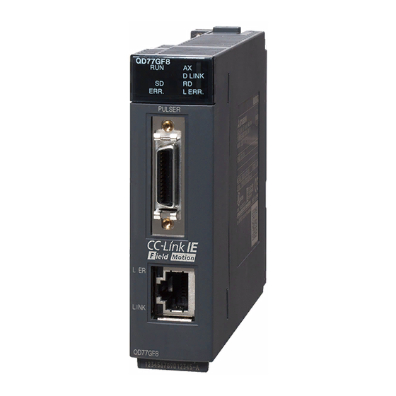
Page 105: Names Of Each Part
Chapter 4 Installation, Wiring and Maintenance of the Product 4.1.2 Names of each part The part names of the Simple Motion module are shown below. QD77GF4 QD77GF8 QD77GF16 Name Description LED (upper part on the front) Refer to this section (1). LED (CC-Link IE Field connector section) Refer to this section (2). - Page 106 Chapter 4 Installation, Wiring and Maintenance of the Product (1) LED (upper part on the front) QD77GF4 QD77GF8 QD77GF16 QD77GF4 QD77GF8 QD77GF16 D LINK D LINK D LINK ERR. L ERR. ERR. L ERR. ERR. L ERR. LED Display Description LED Display Description D LINK...
- Page 107 Chapter 4 Installation, Wiring and Maintenance of the Product (2) CC-Link IE Field Network connector section L ER LINK LED Display Description L ER L ER LED is Receive data error LINK L ER L ER LED is Receive data operates normally. OFF.
-
Page 108: Handling Precautions
Chapter 4 Installation, Wiring and Maintenance of the Product 4.1.3 Handling precautions Handle the Simple Motion module and cable while observing the following precautions. [1] Handling precautions CAUTION Use the programmable controller in an environment that meets the general specifications in the manual "Safety Guidelines", the manual supplied with the main base unit. - Page 109 Chapter 4 Installation, Wiring and Maintenance of the Product [2] Other precautions (1) Main body The main body case is made of plastic. Take care not to drop or apply strong impacts onto the case. Do not remove the PCB of Simple Motion module from the case. Failure to observe this could lead to faults.
-
Page 110: Installation
Chapter 4 Installation, Wiring and Maintenance of the Product 4.2 Installation 4.2.1 Precautions for installation The precautions for installing the Simple Motion module are given below. Refer to this section as well as Section 4.1.3 "Handling precautions" when carrying out the work. Precautions for installation DANGER Completely turn off the externally supplied power used in the system before installing or... -
Page 111: Wiring
Chapter 4 Installation, Wiring and Maintenance of the Product 4.3 Wiring The precautions for wiring the Simple Motion module are given below. Refer to this section as well as Section 4.1.3 "Handling precautions" when carrying out the work. 4.3.1 Precautions for wiring DANGER Completely turn off the externally supplied power used in the system before installation or wiring. -
Page 112: Precautions For Wiring
Chapter 4 Installation, Wiring and Maintenance of the Product [1] Precautions for wiring (1) Use separate cables for connecting to the Simple Motion module and for the power cable that create surge and inductance. (2) The cable for connecting the Simple Motion module can be placed in the duct or secured in place by clamps. - Page 113 Chapter 4 Installation, Wiring and Maintenance of the Product [Wiring example of shielded cable] The following shows a wiring example for noise reduction in the case when the connector (LD77MHIOCON) is used. For forced stop input signal /External command signal/Switching signal Shielded cable Connector (LD77MHIOCON)
- Page 114 Chapter 4 Installation, Wiring and Maintenance of the Product Assembling of connector (LD77MHIOCON) Mount the cable clamp with ground plate to the conductive tape. 4 - 12...
- Page 115 (6) To make this product conform to the EMC directive instruction and Low Voltage Directives, be sure to use an AD75CK type cable clamp (manufactured by Mitsubishi Electric) for grounding connected to the control box and the shielded cable. Inside control box QD77GF 20cm(7.88inch) to...
- Page 116 Chapter 4 Installation, Wiring and Maintenance of the Product [2] Precautions for CC-Link IE Field Network cable wiring This section describes the CC-Link IE Field Network cable wiring and precautions. For network configuration, cables, and hubs used for the wiring, refer to the system configuration.
- Page 117 Chapter 4 Installation, Wiring and Maintenance of the Product (2) Precautions This section describes wiring precautions. (a) Handling of CC-Link IE Field Network cable • Place the CC-Link IE Field Network cable in a duct or clamp them. If not, dangling cable may swing or inadvertently be pulled, resulting in damage to the module or cables or malfunction due to poor contact.
- Page 118 Chapter 4 Installation, Wiring and Maintenance of the Product [3] Example of measure against noise for compliance with the EMC directive. PLC CPU Power supply wiring Power QD77GF supply Q62P PO W ER INPUT 100-240VAC 50/60Hz 105VA OUTPUT 5VDC 3A/24VDC 0.6A ERR.
-
Page 119: Confirming The Installation And Wiring
Chapter 4 Installation, Wiring and Maintenance of the Product 4.4 Confirming the installation and wiring 4.4.1 Items to confirm when installation and wiring are completed Check the following points when completed with the installation of Simple Motion module and wiring. ... -
Page 120: Maintenance
Chapter 4 Installation, Wiring and Maintenance of the Product 4.5 Maintenance 4.5.1 Precautions for maintenance The precautions for servicing the Simple Motion module are given below. Refer to this section as well as Section 4.1.3 "Handling precautions" when carrying out the work. DANGER Completely turn off the externally supplied power used in the system before clearing or tightening the connector screws. - Page 121 Chapter 5 Data Used for Positioning Control Chapter 5 Data Used for Positioning Control The parameters and data used to carry out positioning control with the Simple Motion module are explained in this chapter. With the positioning system using the Simple Motion module, the various parameters and data explained in this chapter are used for control.
-
Page 122: Types Of Data
Chapter 5 Data Used for Positioning Control 5.1 Types of data 5.1.1 Parameters and data required for control The parameters and data required to carry out control with the Simple Motion module include the "setting data", "monitor data" and "control data" shown below. Setting data (Data set beforehand according to the machine and application, and stored in the flash ROM or internal memory (nonvolatile).) Positioning... - Page 123 Chapter 5 Data Used for Positioning Control The following methods are available for data setting: • Set using GX Works2. • Create the sequence program for data setting using GX Works2 and execute it. In this manual, the method using the GX Works2 will be explained. (Refer to "Point"...
- Page 124 Chapter 5 Data Used for Positioning Control Monitor data (Data that indicates the control state. Stored in the buffer memory, and monitors as necessary.) System monitor data Monitors the specifications and the operation history of Simple Motion module. Monitors the data related to the operating axis, such as the current position Axis monitor data and speed.
-
Page 125: Setting Items For Positioning Parameters
Chapter 5 Data Used for Positioning Control 5.1.2 Setting items for positioning parameters The table below lists items set to the positioning parameters. Setting of positioning parameters is done for individual axes for all controls achieved by the Simple Motion module. - Page 126 Chapter 5 Data Used for Positioning Control Expansion Major positioning control Manual control Control control Position control Other control Positioning parameter [Pr.25] Acceleration time 1 – – – – – [Pr.26] Acceleration time 2 – – – – – [Pr.27] Acceleration time 3 –...
-
Page 127: Setting Items For Hpr Parameters
Chapter 5 Data Used for Positioning Control 5.1.3 Setting items for HPR parameters When carrying out "HPR control", the "HPR parameters" must be set. The setting items for the "HPR parameters" are shown below. The "HPR parameters" are set for each axis. Refer to Chapter 8 "HPR control"... -
Page 128: Setting Items For Expansion Parameters
Chapter 5 Data Used for Positioning Control Checking the HPR parameters [Pr.43] to [Pr.57] are checked with the following timing. When the "PLC READY signal [Y0]" output from the PLC CPU to the Simple Motion module changes from OFF to ON. ... -
Page 129: Setting Items For Positioning Data
Chapter 5 Data Used for Positioning Control 5.1.6 Setting items for positioning data Positioning data must be set for carrying out any "major positioning control". The table below lists the items to be set for producing the positioning data. One to 600 positioning data items can be set for each axis. For details of the major positioning controls, refer to Chapter 9 "Major Positioning Control". -
Page 130: Setting Items For Block Start Data
Chapter 5 Data Used for Positioning Control Major positioning control Position control Other control Positioning data [Da.20] Axis to be interpolated 1 : 2 axes, 3 axes, 4 axes –: 1 axis – – – – – – – [Da.21] Axis to be interpolated 2 : 3 axes, 4 axes –: 1 axis, 2 axes –... -
Page 131: Setting Items For Condition Data
Chapter 5 Data Used for Positioning Control 5.1.8 Setting items for condition data When carrying out "high-level positioning control" or using the JUMP instruction in the "major positioning control", the "condition data" must be set as required. The setting items for the "condition data" are shown below. Up to 10 "condition data"... -
Page 132: Types And Roles Of Monitor Data
Chapter 5 Data Used for Positioning Control 5.1.9 Types and roles of monitor data The monitor data area in the buffer memory stores data relating to the operating state of the positioning system, which are monitored as required while the positioning system is operating. - Page 133 Chapter 5 Data Used for Positioning Control [1] Monitoring the system Monitoring the positioning system operation history Monitoring details Corresponding item [Md.1] Whether the system is in the test mode or not In test mode flag [Md.3] Start information Start information [Md.4] Start No.
- Page 134 Chapter 5 Data Used for Positioning Control [2] Monitoring the axis operation state Monitoring the position Monitor details Corresponding item [Md.21] Monitor the current feed machine value. Feed machine value [Md.20] Monitor the current "feed current value". Feed current value [Md.32] Monitor the current target value.
- Page 135 Chapter 5 Data Used for Positioning Control Monitoring the state Monitor details Corresponding item [Md.26] Monitor the axis operation state. Axis operation status [Md.23] Monitor the latest error code that occurred with the axis. Axis error No. [Md.24] Monitor the latest warning code that occurred with the axis. Axis warning No.
-
Page 136: Types And Roles Of Control Data
Chapter 5 Data Used for Positioning Control 5.1.10 Types and roles of control data Operation of the positioning system is achieved through the execution of necessary controls. (Data required for controls are given through the default values when the power is switched ON, which can be modified as required by the sequence program.) Items that can be controlled are described below. - Page 137 Chapter 5 Data Used for Positioning Control [2] Controlling the operation Controlling the operation Control details Corresponding item [Cd.3] Set which positioning to execute (start No.). Positioning start No. [Cd.5] Clear (reset) the axis error ([Md.23]) and warning ([Md.24]). Axis error reset [Cd.6] Issue instruction to restart (When axis operation is stopped).
- Page 138 Chapter 5 Data Used for Positioning Control Controlling the speed Control details Corresponding item [Cd.14] Set new speed when changing speed during operation. New speed value Issue instruction to change speed in operation to [Cd.14] value. [Cd.15] Speed change request (Only during positioning operation and JOG operation).
- Page 139 Chapter 5 Data Used for Positioning Control Control details Corresponding item Set the stop command processing for deceleration stop function Stop command processing for [Cd.42] (deceleration curve re-processing/deceleration curve continuation) deceleration stop selection [Cd.45] Set the device used for speed-position switching. Speed-position switching device selection [Cd.46] Switch speed-position control.
-
Page 140: List Of Parameters
Chapter 5 Data Used for Positioning Control 5.2 List of parameters The setting items of the setting data are explained in this section. • Guide to buffer memory address In the buffer memory address, "n" in "1+150n", etc. indicates a value corresponding to axis No. - Page 141 Chapter 5 Data Used for Positioning Control [Pr.1] Unit setting Set the unit used for defining positioning operations. Choose from the following units depending on the type of the control target: mm, inch, degree, or PLS. Different units can be defined for different axes. (Example) Different units (mm, inch, degree, and PLS) are applicable to different systems: •...
- Page 142 Chapter 5 Data Used for Positioning Control POINT (1) Set the electronic gear within the following range. If the value outside the setting range is set, the error "Outside electronic gear setting range" (error code: 907) will occur. • Product information is before 150920000000000. ...
- Page 143 Chapter 5 Data Used for Positioning Control [Pr.2] Number of pulses per rotation (AP) Set the number of pulses required for a complete rotation of the motor shaft. If you are using the Mitsubishi servo amplifier, set the value given as the "resolution per servomotor rotation"...
- Page 144 Chapter 5 Data Used for Positioning Control [Pr.7] Bias speed at start Set the bias speed (minimum speed) upon starting. When using a stepping motor, etc., set it to start the motor smoothly. (If the motor speed at start is low, the stepping motor does not start smoothly.) The specified "bias speed at start"...
- Page 145 Chapter 5 Data Used for Positioning Control POINT For the 2-axis or more interpolation control, the bias speed at start is applied by the setting of "[Pr.20] Interpolation speed designation method". "0: Composite speed" : Bias speed at start set to the reference axis is applied to the composite command speed.
-
Page 146: Basic Parameters 2
Chapter 5 Data Used for Positioning Control 5.2.2 Basic parameters 2 Setting value, setting range Default Item Buffer memory address Value set with sequence value Value set with GX Works2 program [Pr.8] 10+150n 200000 The setting range differs depending on the "[Pr.1] Unit setting". Speed limit value 11+150n [Pr.9]... -
Page 147: Detailed Parameters 1
Chapter 5 Data Used for Positioning Control 5.2.3 Detailed parameters 1 Setting value, setting range Item Default value Buffer memory address Value set with sequence Value set with GX Works2 program [Pr.11] Backlash compensation 17+150n amount [Pr.12] The setting value range differs according to the "[Pr.1] Unit 18+150n Software stroke limit 2147483647... - Page 148 Chapter 5 Data Used for Positioning Control Setting value, setting range Item Default value Buffer memory address Value set with sequence Value set with GX Works2 program b0 Lower limit b1 Upper limit b2 Not used b3 Stop signal External command/ switching signal...
- Page 149 Chapter 5 Data Used for Positioning Control [Pr.11] Backlash compensation amount The error that occurs due to backlash when moving the machine via gears can be compensated. (When the backlash compensation amount is set, commands equivalent to the compensation amount will be output each time the direction changes during positioning.) HPR direction Pr.44...
- Page 150 Chapter 5 Data Used for Positioning Control Value set with GX Works2 Value set with sequence program [Pr.1] setting value (unit) (unit) 0 to 65535 ( 10 0 to 6553.5 ( m) m) 0 : mm 0 to 65535 ( 10 1 : inch 0 to 0.65535 (inch) inch)
- Page 151 Chapter 5 Data Used for Positioning Control [Pr.14] Software stroke limit selection Set whether to apply the software stroke limit on the "feed current value" or the "feed machine value". The software stroke limit will be validated according to the set value.
- Page 152 Chapter 5 Data Used for Positioning Control [Pr.18] M code ON signal output timing This parameter sets the M code ON signal output timing. Choose either WITH mode or AFTER mode as the M code ON signal output timing. WITH mode .... An M code is output and the M code ON signal AFTER mode ..
- Page 153 Chapter 5 Data Used for Positioning Control [Pr.19] Speed switching mode Set whether to switch the speed switching mode with the standard switching or front-loading switching mode. 0 : Standard switching ....Switch the speed when executing the next positioning data. 1 : Front-loading switching ..
- Page 154 Chapter 5 Data Used for Positioning Control [Pr.21] Feed current value during speed control Specify whether you wish to enable or disable the update of "[Md.20] Feed current value" while operations are performed under the speed control (including the speed control in speed-position and position-speed switching control). 0: The update of the feed current value is disabled The feed current value will not change.
- Page 155 Chapter 5 Data Used for Positioning Control [Pr.80] External input signal selection Set whether to use "external input signal of servo amplifier" or "buffer memory of QD77GF" as an external input signal (upper/lower limit signal or proximity dog signal)". 1: External input signal of servo amplifier 2: Buffer memory of QD77GF POINT (1) When "2: Buffer memory of QD77GF"...
- Page 156 Chapter 5 Data Used for Positioning Control (b) A-phase/B-phase multiplied by 2 The positioning address increases or decreases at twice rising or twice falling edges of A-phase/B-phase. [Pr.22] Input signal logic selection Positive logic Negative logic Forward run Reverse run Forward run Reverse run A-phase...
- Page 157 Chapter 5 Data Used for Positioning Control [Pr.82] Forced stop valid/invalid selection Set the forced stop valid/invalid. (Only the value specified against the axis 1 is valid.) All axes of the servo amplifier are made to batch forced stop when the forced stop input signal is turned on.
-
Page 158: Detailed Parameters 2
Chapter 5 Data Used for Positioning Control 5.2.4 Detailed parameters 2 Setting value, setting range Default Item Buffer memory address Value set with sequence value Value set with GX Works2 program 36+150n [Pr.25] Acceleration time 1 37+150n 38+150n [Pr.26] Acceleration time 2 39+150n 40+150n [Pr.27] Acceleration time 3... - Page 159 Chapter 5 Data Used for Positioning Control Setting value, setting range Default Item Buffer memory address Value set with sequence Value set with GX Works2 value program [Pr.41] The setting value range differs depending on the "[Pr.1] Unit 60+150n Allowable circular setting".
- Page 160 Chapter 5 Data Used for Positioning Control [Pr.28] Deceleration time 1 to [Pr.30] Deceleration time 3 These parameters set the time for the speed to decrease from the "[Pr.8] Speed limit value" ("[Pr.31] JOG speed limit value" at JOG operation control) to zero during a positioning operation.
- Page 161 Chapter 5 Data Used for Positioning Control [Pr.34] Acceleration/deceleration process selection Set whether to use trapezoid acceleration/deceleration or S-curve acceleration/ deceleration for the acceleration/deceleration process. Note) Refer to Section 13.7.6 "Acceleration/deceleration processing function" for details. Velocity Velocity The acceleration and deceleration The acceleration and deceleration are linear.
- Page 162 Chapter 5 Data Used for Positioning Control [Pr.36] Rapid stop deceleration time Set the time to reach speed 0 from "[Pr.8] Speed limit value" ("[Pr.31] JOG speed limit value" at JOG operation control) during the rapid stop. The illustration below shows the relationships with other parameters.
- Page 163 Chapter 5 Data Used for Positioning Control [Pr.40] Positioning complete signal output time Set the output time of the positioning complete signal output from the Simple Motion module. A positioning completes when the specified dwell time has passed after the Simple Motion module had terminated the command output.
- Page 164 Chapter 5 Data Used for Positioning Control [Pr.41] Allowable circular interpolation error width The allowable error range of the calculated arc path and end point address is set. If the error of the calculated arc path and end point address is within the set range, circular interpolation will be carried out to the set end point address while compensating the error with spiral interpolation.
- Page 165 Chapter 5 Data Used for Positioning Control [Pr.42] External command function selection Select a command with which the external command signal should be associated. 0: External positioning start The external command signal input is used to start a positioning operation. 1: External speed change request The external command signal input is used to change the speed in the current positioning operation.
- Page 166 Chapter 5 Data Used for Positioning Control [Pr.84] Restart allowable range when servo OFF to ON (1) Restart function at switching servo OFF to ON The restart function at switching servo OFF to ON performs continuous positioning operation (positioning start, restart) when switching servo OFF to ON while the Simple Motion module is stopped (including forced stop, servo forced stop).
- Page 167 Chapter 5 Data Used for Positioning Control (2) Setting method For performing restart at switching servo OFF to ON, set the restart allowable range in the following buffer memory. Buffer memory address Default value Item Setting range 64+150n [Pr.84] Restart allowable range 0, 1 to 327680 (PLS) 65+150n when servo OFF to ON...
- Page 168 Chapter 5 Data Used for Positioning Control (g) Restart can also be executed while the positioning start signal is ON. However, do not set the positioning start signal from OFF to ON during a stop. If the positioning start signal is switched from OFF to ON, positioning is performed from the positioning data number set in "[Cd.3] Positioning start No."...
- Page 169 Chapter 5 Data Used for Positioning Control (3) Condition selection at mode switching Set the valid/invalid of switching conditions for switching control mode. [RJ010 mode] 0: Switching conditions valid (for switching control mode) 1: Zero speed ON condition invalid (for switching control mode) [CiA402 mode] 0: Check the switching conditions in Simple Motion module 1: According to the servo amplifier specification...
-
Page 170: Hpr Basic Parameters
Chapter 5 Data Used for Positioning Control 5.2.5 HPR basic parameters Setting value, setting range Default Item Buffer memory address Value set with value Value set with GX Works2 sequence program 0 : Proximity dog method [RJ010 mode] 4 : Count method 1) [RJ010 mode] 5 : Count method 2) [RJ010 mode] [Pr.43] 6 : Data set method [RJ010 mode]... - Page 171 Chapter 5 Data Used for Positioning Control 0 : Proximity dog method [RJ010 mode] (1) Start machine HPR. (Start movement at the "[Pr.46] HPR speed" in the "[Pr.44] HPR direction".) (2) Detect the proximity dog ON, and start deceleration. HPR speed Pr.46 (3) Decelerate to "[Pr.47] Creep speed", and move with the creep speed.
- Page 172 Chapter 5 Data Used for Positioning Control 6 : Data set method [RJ010 mode] The position where the machine HPR has been made will be the HP. (Perform after the servo amplifier has been turned ON and the servomotor has been rotated at least once using the JOG or similar operation.
- Page 173 Chapter 5 Data Used for Positioning Control [Pr.45] HP address Set the address used as the reference point for positioning control (ABS system). (When the machine HPR is completed, the stop position address is changed to the address set in "[Pr.45] HP address". At the same time, the "[Pr.45] HP address" is stored in "[Md.20] Feed current value"...
- Page 174 Chapter 5 Data Used for Positioning Control [Pr.47] Creep speed [RJ010 mode] Set the creep speed after proximity dog ON (the low speed just before stopping after decelerating from the HPR speed). The creep speed is set within the following range. ([Pr.46] HPR speed) ([Pr.47] Creep speed) ([Pr.7] Bias speed at start)
- Page 175 Chapter 5 Data Used for Positioning Control [Pr.48] HPR retry [RJ010 mode] Set whether to carry out HPR retry. When the HPR retry function is validated and the machine HPR is started, first the axis will move in the HPR direction (1)). If the upper/lower limit signal turns OFF before the proximity dog signal ON is detected (2)), the axis will decelerate to a stop, and then will move in the direction opposite the HPR direction (3)).
-
Page 176: Hpr Detailed Parameters
Chapter 5 Data Used for Positioning Control 5.2.6 HPR detailed parameters Setting value, setting range Default Item Buffer memory address Value set with sequence value Value set with GX Works2 program [Pr.50] The setting value range differs depending on the "[Pr.1] Unit Setting for the movement 80+150n amount after proximity dog... - Page 177 Chapter 5 Data Used for Positioning Control [Pr.50] Setting for the movement amount after proximity dog ON [RJ010 mode] When using the count method 1) or 2), set the movement amount to the HP after the proximity dog signal turns ON. (The movement amount after proximity dog ON should be equal to or greater than the sum of the "distance covered by the deceleration from the HPR speed to the creep speed"...
- Page 178 Chapter 5 Data Used for Positioning Control [Pr.52] HPR deceleration time selection Set which of "deceleration time 0 to 3" to use for the deceleration time during HPR. Valid only during fast HPR. [CiA402 mode] 0 : Use the value set in "[Pr.10] Deceleration time 0". 1 : Use the value set in "[Pr.28] Deceleration time 1".
- Page 179 Chapter 5 Data Used for Positioning Control [Pr.54] HPR torque limit value [RJ010 mode] Set the value to limit the servomotor torque after reaching the creep speed during machine HPR. Refer to Section 13.4.2 "Torque limit function" for details on the torque limits. [Pr.55] Operation setting for incompletion of HPR Set whether the positioning control is executed or not (When the HPR request flag is ON.).
- Page 180 Chapter 5 Data Used for Positioning Control [Pr.56] Speed designation during HP shift [RJ010 mode] Set the operation speed for when a value other than "0" is set for "[Pr.53] HP shift amount". Select the setting from "[Pr.46] HPR speed" or "[Pr.47] Creep speed". 0 : Designate "[Pr.46] HPR speed"...
-
Page 181: Expansion Parameters
Chapter 5 Data Used for Positioning Control 5.2.7 Expansion parameters Setting value, setting range Default Item Buffer memory address Value set with sequence value Value set with GX Works2 program [RJ010 mode] [RJ010 mode] 0: 0.88ms 1: 1.77ms 2: 3.55ms [Pr.96] (Note-1) [CiA402 mode]... - Page 182 Chapter 5 Data Used for Positioning Control [Pr.113] Servo parameter transmission [RJ010 mode] When MR-J4-B is used, set whether to transmit the servo parameter from the Simple Motion module to the servo amplifier. 0: Transfer the servo parameter 1: Do not transfer the servo parameter When using the servo amplifier excluding MR-J4-B, the setting is ignored and it operates as if "1: Do not transfer the servo parameter"...
-
Page 183: Servo Parameters
Chapter 5 Data Used for Positioning Control 5.2.8 Servo parameters (1) Servo amplifier setting Default Item Setting details Setting range Buffer memory address value Virtual 0: Use for the actual servo servo Set whether to use as the virtual servo amplifier [Pr.101] 28401+100n... -
Page 184: List Of Positioning Data
Chapter 5 Data Used for Positioning Control 5.3 List of positioning data Before explaining the positioning data setting items [Da.1] to [Da.10], [Da.20] to [Da.22] the configuration of the positioning data will be shown below. The positioning data stored in the buffer memory of Simple Motion module has the following type of configuration. - Page 185 Chapter 5 Data Used for Positioning Control The descriptions that follow relate to the positioning data set items [Da.1] to [Da.10], [Da.20] to [Da.22]. (The buffer memory addresses shown are those of the "positioning data No. 1".) • Guide to buffer memory address In the buffer memory address, "n"...
- Page 186 Chapter 5 Data Used for Positioning Control Setting value Default Item Buffer memory address Value set with GX Works2 Value set with sequence program value 00: Positioning complete [Da.1] Operation pattern Operation 01: Continuous positioning control pattern 11: Continuous path control 01h: ABS Linear 1 02h: INC Linear 1 03h: Feed 1...
- Page 187 Chapter 5 Data Used for Positioning Control Setting value, setting range Default Item Buffer memory address Value set with sequence Value set with GX Works2 value program [Da.6] 6006+1000n Positioning address/ 6007+1000n The setting value range differs according to the "[Da.2] Control movement amount method".
- Page 188 Chapter 5 Data Used for Positioning Control [Da.1] Operation pattern The operation pattern designates whether positioning of a certain data No. is to be ended with just that data, or whether the positioning for the next data No. is to be carried out in succession.
- Page 189 Chapter 5 Data Used for Positioning Control [Da.4] Deceleration time No. Set which of "deceleration time 0 to 3" to use for the deceleration time during positioning. 0: Use the value set in "[Pr.10] Deceleration time 0". 1: Use the value set in "[Pr.28] Deceleration time 1". 2: Use the value set in "[Pr.29] Deceleration time 2".
- Page 190 Chapter 5 Data Used for Positioning Control (3) Speed-position switching control INC mode: Set the amount of movement after the switching from speed control to position control. ABS mode: Set the absolute address which will be the target value after speed control is switched to position control.
- Page 191 Chapter 5 Data Used for Positioning Control When "[Pr.1] Unit setting" is "mm" The table below lists the control methods that require the setting of the positioning address or movement amount and the associated setting ranges. (With any control method excluded from the table below, neither the positioning address nor the movement amount needs to be set.) Value set with sequence program Value set with GX Works2...
- Page 192 Chapter 5 Data Used for Positioning Control When "[Pr.1] Unit setting" is "degree" The table below lists the control methods that require the setting of the positioning address or movement amount and the associated setting ranges. (With any control method excluded from the table below, neither the positioning address nor the movement amount needs to be set.) Value set with sequence program Value set with GX Works2...
- Page 193 Chapter 5 Data Used for Positioning Control When "[Pr.1] Unit setting" is "PLS" The table below lists the control methods that require the setting of the positioning address or movement amount and the associated setting ranges. (With any control method excluded from the table below, neither the positioning address nor the movement amount needs to be set.) Value set with GX Works2 Value set with sequence program...
- Page 194 Chapter 5 Data Used for Positioning Control When "[Pr.1] Unit setting" is "inch" The table below lists the control methods that require the setting of the positioning address or movement amount and the associated setting ranges. (With any control method excluded from the table below, neither the positioning address nor the movement amount needs to be set.) Value set with sequence program Value set with GX Works2...
- Page 195 Chapter 5 Data Used for Positioning Control When "[Pr.1] Unit setting" is "mm" The table below lists the control methods that require the setting of the arc address and shows the setting range. (With any control method excluded from the table below, the arc address does not need to be set.) Value set with sequence program Value set with GX Works2...
- Page 196 Chapter 5 Data Used for Positioning Control When "[Pr.1] Unit setting" is "inch" The table below lists the control methods that require the setting of the arc address and shows the setting range. (With any control method excluded from the table below, the arc address does not need to be set.) Value set with sequence program Value set with GX Works2...
- Page 197 Chapter 5 Data Used for Positioning Control [Da.9] Dwell time/JUMP designation positioning data No. Set the "dwell time" or "positioning data No." corresponding to the "[Da.2] Control method". When a method other than "JUMP instruction" is set for "[Da.2] Control method" ..
- Page 198 Chapter 5 Data Used for Positioning Control [Da.10] M code/Condition data No./Number of LOOP to LEND repetitions Set an "M code", a "condition data No.", or the "Number of LOOP to LEND repetitions" depending on how the "[Da.2] Control method" is set. ...
- Page 199 Chapter 5 Data Used for Positioning Control [Da.20] Axis to be interpolated No.1 to [Da.22] Axis to be interpolated No.3 Set the axis to be interpolated to execute the 2 to 4-axis interpolation operation. • 2-axis interpolation ..Set the target axis number in "[Da.20] Axis to be interpolated No.1".
-
Page 200: List Of Block Start Data
Chapter 5 Data Used for Positioning Control 5.4 List of block start data The illustrations below show the organization of the block start data stored in the buffer memory of Simple Motion module. The block start data setting items [Da.11] to [Da.14] are explained in the pages that follow. - Page 201 Chapter 5 Data Used for Positioning Control REMARK To perform a high-level positioning control using block start data, set a number between 7000 and 7004 to the "[Cd.3] Positioning start No." and use the "[Cd.4] Positioning starting point No." to specify a point number between 1 and 50, a position counted from the beginning of the block.
- Page 202 Chapter 5 Data Used for Positioning Control Setting value Default Item Buffer memory address value Value set with GX Works2 Value set with sequence program 0 : End [Da.11] Shape 0 0 0 1 : Continue 0000 22000+400n Shape Positioning data No.: [Da.12] 1 to 600 Start data No.
- Page 203 Chapter 5 Data Used for Positioning Control [Da.11] Shape Set whether to carry out only the local "block start data" and then end control, or to execute the "block start data" set in the next point. Setting value Setting details 0 : End Execute the designated point's "block start data", and then complete the control.
-
Page 204: List Of Condition Data
Chapter 5 Data Used for Positioning Control 5.5 List of condition data The illustrations below show the organization of the condition data stored in the buffer memory of Simple Motion module. The condition data setting items [Da.15] to [Da.19] and [Da.23] to [Da.26] are explained in the pages that follow. No.10 Buffer memory Setting item... - Page 205 Chapter 5 Data Used for Positioning Control REMARK To perform a high-level positioning control using block start data, set a number between 7000 and 7004 to the "[Cd.3] Positioning start No." and use the "[Cd.4] Positioning starting point No." to specify a point number between 1 and 50, a position counted from the beginning of the block.
- Page 206 Chapter 5 Data Used for Positioning Control Setting value Default Item Buffer memory address value Value set with GX Works2 Value set with sequence program 01 : Device X 02 : Device Y Condition target [Da.15] 03 : Buffer memory (1-word) Condition target 04 : Buffer memory (2-word) 05 : Positioning data No.
- Page 207 Chapter 5 Data Used for Positioning Control [Da.15] Condition target Set the condition target as required for each control. Setting value Setting details 01H : Device X Set the input/output signal ON/OFF as the conditions. 02H : Device Y 03H : Buffer memory (1-word) Set the value stored in the buffer memory as the condition. 03H: The target buffer memory is "1-word (16 bits)"...
- Page 208 Chapter 5 Data Used for Positioning Control [Da.18] Parameter 1 Set the parameters as required for the "[Da.16] Condition operator" and "[Da.23] Number of simultaneous starting axes". [Da.23] Number of [Da.16] Condition operator simultaneous Setting value Setting details starting axes 01H : ...
- Page 209 Chapter 5 Data Used for Positioning Control [Da.23] Number of simultaneous starting axes Set the number of simultaneous starting axes to execute the simultaneous start. 2: Simultaneous start by 2 axes of the starting axis and axis set in "[Da.24] Simultaneous starting axis No.1".
-
Page 210: List Of Monitor Data
Chapter 5 Data Used for Positioning Control 5.6 List of monitor data The setting items of the monitor data are explained in this section. • Guide to buffer memory address In the buffer memory address, "n" in "2406+100n", etc. indicates a value corresponding to axis No. - Page 211 Chapter 5 Data Used for Positioning Control Default value Buffer memory address Reading the monitor value Monitoring is carried out with a decimal. Monitor Storage value 4000 value 0: Not in test mode 1: In test mode (Unless noted in particular, the monitor value is saved as binary data.) 5 - 91...
- Page 212 Chapter 5 Data Used for Positioning Control Storage item Storage details Reading the monitor value [Storage details] This area stores the start information (restart flag, start origin, and start axis): Restart flag: Indicates whether the operation has or has not been halted and restarted.
- Page 213 Chapter 5 Data Used for Positioning Control Default value Buffer memory address 0000H Md.8 4092 Start history pointer Indicates a pointer No. that is next to the pointer No. assigned to the latest of the existing starting history records. Pointer No. Md.3 4012 4017 4022 4027 4032 4037 4042...
- Page 214 Chapter 5 Data Used for Positioning Control Storage item Storage details Reading the monitor value Monitoring is carried out with a hexadecimal display. The starting time (Year: month) is Buffer memory (stored with BCD code) [Md.54] stored. Monitor value Start Year: month 0 0 0 1 0 0 0 0 0 0 0 1 1 0...
- Page 215 Chapter 5 Data Used for Positioning Control Default value Buffer memory address 0000H 0000H Md.8 4092 0000H Start history pointer Indicates a pointer No. that is next to the pointer No. assigned to the latest of the existing starting history records. Pointer No.
- Page 216 Chapter 5 Data Used for Positioning Control Storage item Storage details Reading the monitor value Monitoring is carried out with a decimal display. Stores an axis No. in which an [Md.9] error occurred. Monitor Storage value Axis in which value 1: Axis 1 5: Axis 5 9: Axis 9...
- Page 217 Chapter 5 Data Used for Positioning Control Default value Buffer memory address Md.13 4157 Error history pointer Indicates a pointer No. that is next to the pointer No. assigned to the latest of the existing error history records. Pointer No. 0000H Md.9 Axis in which the...
- Page 218 Chapter 5 Data Used for Positioning Control Storage item Storage details Reading the monitor value Monitoring is carried out with a decimal display. Stores an axis No. in which a [Md.14] warning occurred. Monitor Storage value Axis in which value 1: Axis 1 5: Axis 5 9: Axis 9...
- Page 219 Chapter 5 Data Used for Positioning Control Default value Buffer memory address Md.18 4222 Warning history pointer Indicates a pointer No. that is next to the pointer No. assigned to the latest of the existing warning history records. Pointer No. Md.14 0000H Axis in which the...
- Page 220 Chapter 5 Data Used for Positioning Control Storage item Storage details Reading the monitor value Stores the number of write accesses to the flash ROM after the power is switched ON. [Md.19] The count is cleared to "0" Monitoring is carried out with a decimal display. when the number of write Number of write Storage value...
- Page 221 Chapter 5 Data Used for Positioning Control Default value Buffer memory address 4224 4225 4231 QD77GF4: 2000H QD77GF8: 2001H 31332 QD77GF16: 2002H 4006 Factory-set product information 4007 4011 5 - 101...
- Page 222 Chapter 5 Data Used for Positioning Control Storage item Storage details Reading the monitor value [RJ010 mode] Monitoring is carried out with a decimal display. Monitor Storage value Stores the current operation value 0: 0.88ms cycle. 1: 1.77ms [Md.132] 2: 3.55ms Operation cycle [CiA402 mode] setting...
- Page 223 Chapter 5 Data Used for Positioning Control Default value Buffer memory address [RJ010 mode] 4238 [CiA402 mode] 0000H 4239 4008 4009 5 - 103...
-
Page 224: Axis Monitor Data
Chapter 5 Data Used for Positioning Control 5.6.2 Axis monitor data Storage item Storage details The currently commanded address is stored. (Different from the actual motor position during operation) The current position address is stored. If "degree" is selected as the unit, the addresses will have a ring structure for values between 0 and 359.99999 degrees. - Page 225 Chapter 5 Data Used for Positioning Control Default Reading the monitor value Buffer memory address value 2400+100n 0000H 2401+100n Monitoring is carried out with a hexadecimal display. Low-order buffer memory Example) 2400 Monitor value High-order buffer memory Example) 2401 Sorting (High-order buffer memory) (Low-order buffer memory) 2402+100n 0000H...
- Page 226 Chapter 5 Data Used for Positioning Control Storage item Storage details Whenever an axis warning is reported, a related warning code is stored. This area stores the latest warning code always. (Whenever an axis warning is reported, a new warning code replaces the stored warning code.) [Md.24] Axis warning No.
- Page 227 Chapter 5 Data Used for Positioning Control Default Reading the monitor value Buffer memory address value Monitoring is carried out with a hexadecimal display. Monitor Axis warning No. value 0000H 2407+100n For details of warning codes, refer to Section 16.5 "List of warnings".
- Page 228 Chapter 5 Data Used for Positioning Control Storage item Storage details The speed which is actually output as a command at that time in each axis is stored. (May be different from the actual motor speed) "0" is stored when the axis is at a stop. [Md.28] Axis feedrate Refresh cycle: Operation cycle POINT...
- Page 229 Chapter 5 Data Used for Positioning Control Default Reading the monitor value Buffer memory address value Monitoring is carried out with a hexadecimal. Low-order buffer memory Example) 2412 Monitor value High-order buffer memory Example) 2413 2412+100n 0000H 2413+100n Sorting (High-order buffer memory) (Low-order buffer memory) Unit conversion table Md.28 Converted from...
- Page 230 Chapter 5 Data Used for Positioning Control Storage item Storage details This area stores the states (ON/OFF) of various flags. Information on the following flags is stored. In speed control flag This signal that comes ON under the speed control can be used to judge whether the operation is performed under the speed control or position control.
- Page 231 Chapter 5 Data Used for Positioning Control Default Reading the monitor value Buffer memory address value Monitoring is carried out with a hexadecimal display. Monitor value Buffer 0 0 0 0 0 0 0 0 0 0 0 0 1 0 0 0 memory Not used Default...
- Page 232 Chapter 5 Data Used for Positioning Control Storage item Storage details This area stores the target value ([Da.6] Positioning address/movement amount) for a positioning operation. At the beginning of positioning control and current value changing: Stores the value of "[Da.6] Positioning address/movement amount". [Md.32] Target value ...
- Page 233 Chapter 5 Data Used for Positioning Control Default Reading the monitor value Buffer memory address value Monitoring is carried out with a decimal display. Monitor Decimal integer value value Unit conversion table Md.32 2418+100n Unit conversion Unit 2419+100n 10 inch degree Actual Target value...
- Page 234 Chapter 5 Data Used for Positioning Control Storage item Storage details [RJ010 mode] The "[Pr.17] Torque limit setting value", "[Cd.101] Torque output setting value", "[Cd.22] New torque value/forward new torque value" or "[Pr.54] HPR torque limit value" is stored. [CiA402 mode] The "[Pr.17] Torque limit setting value", "[Cd.101] Torque output setting value"...
- Page 235 Chapter 5 Data Used for Positioning Control Default Reading the monitor value Buffer memory address value Monitoring is carried out with a decimal display. Monitor value 2426+100n Storage value 1 to 1000 (%) Monitoring is carried out with a decimal display. Monitor Storage value value...
- Page 236 Chapter 5 Data Used for Positioning Control Storage item Storage details If the speed exceeds the "[Pr.8] Speed limit value" ("[Pr.31] JOG speed limit value" at JOG operation control) due to a speed change or override, the speed limit functions, and the in speed limit flag turns ON. ...
- Page 237 Chapter 5 Data Used for Positioning Control Default Reading the monitor value Buffer memory address value Monitoring is carried out with a decimal display. Monitor Storage value 2430+100n value 0: Not in speed limit (OFF) 1: In speed limit (ON) Monitoring is carried out with a decimal display.
- Page 238 Chapter 5 Data Used for Positioning Control Storage item Storage details This area stores the positioning data No. attached to the positioning data that was executed last time. The value is retained until a new positioning operation is executed. [Md.46] Last executed positioning data No.
- Page 239 Chapter 5 Data Used for Positioning Control Default Reading the monitor value Buffer memory address value Monitoring is carried out with a decimal display. Storage value 2437+100n 1 to 600, 9001 to 9003 Monitor value Information is stored in the following addresses: Stored address Stored item Reference...
- Page 240 Chapter 5 Data Used for Positioning Control Storage item Storage details This area stores the travel distance during the HPR travel to the zero point that was executed last time. "0" is stored at machine HPR start. For setting units [Md.100] HPR re-travel value Example) mm [RJ010 mode]...
- Page 241 Chapter 5 Data Used for Positioning Control Default Reading the monitor value Buffer memory address value Monitoring is carried out with a hexadecimal display. Low-order buffer memory Example) 2448 Monitor value 2448+100n 0000H 2449+100n High-order buffer memory Example) 2449 Sorting 2450+100n 0000H (High-order buffer memory) (Low-order buffer memory)
- Page 242 Chapter 5 Data Used for Positioning Control Storage item Storage details When a servo parameter error occurs, the area that corresponds to the parameter number affected by the error comes ON. When the "[Cd.5] Axis error reset" (axis control data) is set to ON after remove the [Md.107] Parameter error No.
- Page 243 Chapter 5 Data Used for Positioning Control Default Reading the monitor value Buffer memory address value Monitoring is carried out with a decimal display. Storage value Monitor value Storage value Parameter No. 1 to 64 PA01 to PA64 64 to 128 PB01 to PB64 129 to 192 PC01 to PC64...
- Page 244 Chapter 5 Data Used for Positioning Control Storage item Storage details The rate of regenerative power to the allowable regenerative power is indicated as a percentage. When the regenerative option is used, the rate to the allowable regenerative [Md.109] Regenerative load ratio power of the option is indicated.
- Page 245 Chapter 5 Data Used for Positioning Control Default Reading the monitor value Buffer memory address value Monitoring is carried out with a decimal display. Monitor 2478+100n value Regenerative load ratio Monitoring is carried out with a decimal display. Monitor 2479+100n value Effective load torque ratio Monitoring is carried out with a decimal display.
- Page 246 Chapter 5 Data Used for Positioning Control Storage item Storage details This area stores the Statusword. [Md.117] Statusword [CiA402 mode] Refresh cycle: Operation cycle [RJ010 mode] "[Pr.17] Torque limit setting value", "[Cd.101] Torque output setting value", "[Cd.113] New reverse torque value" or "[Pr.54] HPR torque limit value" is stored. [CiA402 mode] "[Pr.17] Torque limit setting value", "[Cd.101] Torque output setting value"...
- Page 247 Chapter 5 Data Used for Positioning Control Default Reading the monitor value Buffer memory address value Monitoring is carried out with a hexadecimal display. Buffer memory Stored items Meaning Ready to switch on Switched on Operation enabled 0000H 2482+100n Fault Voltage enabled 0:OFF Quick stop...
- Page 248 Chapter 5 Data Used for Positioning Control Storage item Storage details This area stores the command speed during speed control mode. "0" is stored other than during speed control mode. [Md.122] Speed during command Refresh cycle: Operation cycle (Speed control mode only) ...
- Page 249 Chapter 5 Data Used for Positioning Control Default Reading the monitor value Buffer memory address value Monitoring is carried out with a decimal display. Monitor value 2492+100n Unit conversion table Md.122 2493+100n Unit conversion Unit 10 mm/min inch/min degree/min Actual Md.122 Speed during command PLS/s...
-
Page 250: List Of Control Data
Chapter 5 Data Used for Positioning Control 5.7 List of control data The setting items of the control data are explained in this section. • Guide to buffer memory address In the buffer memory address, "n" in "4303+100n", etc. indicates a value corresponding to axis No. - Page 251 Chapter 5 Data Used for Positioning Control Default Setting value Buffer memory address value Set with a decimal. Setting value Flash ROM write request 1: Requests write access to flash ROM. 5900 The Simple Motion module resets the value to "0" automatically when the write access completes.
- Page 252 Chapter 5 Data Used for Positioning Control Setting item Setting details Set whether "[Md.48] Deceleration start flag" is made valid or invalid. Fetch cycle: At PLC READY ON [Cd.41] Deceleration start flag valid POINT The "[Cd.41] Deceleration start flag valid" become valid when the PLC READY signal [Y0] turns from OFF to ON.
- Page 253 Chapter 5 Data Used for Positioning Control Default Setting value Buffer memory address value Set with a decimal. Setting value 5905 Deceleration start flag valid 0: Deceleration start flag invalid 1: Deceleration start flag valid Set with a decimal. Setting value 5907 Stop command processing for deceleration...
-
Page 254: Axis Control Data
Chapter 5 Data Used for Positioning Control 5.7.2 Axis control data Setting item Setting details Set the positioning start No. (Only 1 to 600 for the Pre-reading start function. For details, refer to Section 13.7.7 "Pre-reading start function".) [Cd.3] Positioning start No. Fetch cycle: At start Note) After the positioning start is requested, do not change the setting value before the start complete signal ([Md.31] Status) is turned ON. - Page 255 Chapter 5 Data Used for Positioning Control Default Setting value Buffer memory address value Set with a decimal. Setting value 4300+100n Positioning data No. : Positioning data No. 1 to 600 : Block start designation 7000 to7004 : Machine HPR 9001 : Fast-HPR 9002...
- Page 256 Chapter 5 Data Used for Positioning Control Setting item Setting details The M code ON signal turns OFF. [Cd.7] M code OFF request Fetch cycle: Operation cycle Validates or invalidates external command signals. [Cd.8] External command valid Fetch cycle: At request by external command signal ...
- Page 257 Chapter 5 Data Used for Positioning Control Default Setting value Buffer memory address value Set with a decimal. Setting value M code OFF request 4304+100n 1: M code ON signal turns OFF After the M code ON signal turns OFF, "0" is stored by the Simple Motion module automatically.
- Page 258 Chapter 5 Data Used for Positioning Control Setting item Setting details Enables or disables modifications to the acceleration/deceleration time during a [Cd.12] Acceleration/deceleration time speed change. change value during speed change, enable/disable Fetch cycle: At change request To use the positioning operation speed override function, use this data item to specify an "override"...
- Page 259 Chapter 5 Data Used for Positioning Control Default Setting value Buffer memory address value Set with a decimal. Setting value Acceleration/deceleration time change value 4312+100n during speed change, enable/disable : Enables modifications to acceleration/deceleration time Other than 1: Disables modifications to acceleration/deceleration time Set with a decimal.
- Page 260 Chapter 5 Data Used for Positioning Control Setting item Setting details Use this data item to set the amount of movement by inching. The machine performs a JOG operation if "0" is set. Set a value within the following range: inch degree [Pr.1] Unit...
- Page 261 Chapter 5 Data Used for Positioning Control Default Setting value Buffer memory address value Set with a decimal. Actual value Cd.16 Inching movement amount Conversion into an integer value Unit conversion table ( Cd.16 ) Unit Setting value 4317+100n inch (Decimal) degree Example: When the "...
- Page 262 Chapter 5 Data Used for Positioning Control Setting item Setting details The sequence program can use this data item to forcibly turn the HPR request flag from ON to OFF. Fetch cycle: 14.2 [ms] [RJ010 mode] [Cd.19] HPR request flag OFF request 16.0 [ms] [CiA402 mode] POINT This parameter is made valid when the increment system is valid.
- Page 263 Chapter 5 Data Used for Positioning Control Default Setting value Buffer memory address value Set with a decimal. Setting value HPR request flag OFF request 4321+100n 1: Turns the "HPR request flag" from ON to OFF. The Simple Motion module resets the value to "0" automatically when the HPR request flag is turned OFF.
- Page 264 Chapter 5 Data Used for Positioning Control Setting item Setting details During the speed control stage of the speed-position switching control (INC mode), it is possible to change the specification of the movement amount during the position control stage. For that, use this data item to specify a new movement amount.
- Page 265 Chapter 5 Data Used for Positioning Control Default Setting value Buffer memory address value Set with a decimal. Speed-position switching Cd.23 Actual value control movement amount change register Conversion into an integer value Unit conversion table ( Cd.23 ) Unit 4326+100n Setting value inch...
- Page 266 Chapter 5 Data Used for Positioning Control Setting item Setting details Set whether the switching signal set in "[Cd.45] Speed-position switching device selection" is enabled or not. [Cd.26] Position-speed switching enable flag Fetch cycle: At switching request When changing the target position during a positioning operation, use this data item to specify a new positioning address.
- Page 267 Chapter 5 Data Used for Positioning Control Default Setting value Buffer memory address value Set with a decimal. Setting value Position-speed switching enable flag 0: Position control will not be taken over by 4332+100n speed control even when the signal set in "...
- Page 268 Chapter 5 Data Used for Positioning Control Setting item Setting details Use these data items to specify a start data No. of own axis at multiple axes simultaneous starting. [Cd.30] Simultaneous starting own axis start data No. Fetch cycle: At start ...
- Page 269 Chapter 5 Data Used for Positioning Control Default Setting value Buffer memory address value 4340+100n 4341+100n Set with a decimal. Setting value Cd.30 Simultaneous starting own 4342+100n axis start data No. Cd.31 Cd.33 Simultaneous starting axis start data No. 1 to 600 4343+100n Set with a decimal.
- Page 270 Chapter 5 Data Used for Positioning Control Setting item Setting details To skip the current positioning operation, set "1" in this data item. [Cd.37] Skip command Fetch cycle: Operation cycle (During positioning operation) This data item specifies the teaching result write destination. ...
- Page 271 Chapter 5 Data Used for Positioning Control Default Setting value Buffer memory address value Set with a decimal. Setting value Skip request 4347+100n Issues a skip request to have the machine decelerate, stop, and then start the next positioning operation. The Simple Motion module resets the value to "0"...
- Page 272 Chapter 5 Data Used for Positioning Control Setting item Setting details Set the number of simultaneous starting axes and target axis. When "2" is set to the number of simultaneous starting axes, set the target axis No. to the simultaneous starting axis No. 1. When "3"...
- Page 273 Chapter 5 Data Used for Positioning Control Default Setting value Buffer memory address value Set with a hexadecimal. Setting value Simultaneous starting axis No.1 0000H 4339+100n 0 to F: Axis 1 to Axis 16 Simultaneous starting axis No.2 0 to F: Axis 1 to Axis 16 Simultaneous starting axis No.3 0 to F: Axis 1 to Axis 16 Number of simultaneous starting axes...
- Page 274 Chapter 5 Data Used for Positioning Control Setting item Setting details Sets the torque output value. Set a ratio against the rated torque in percentage unit. Fetch cycle: At start POINT If the "[Cd.101] Torque output setting value" is "0", the "[Pr.17] Torque limit setting value"...
- Page 275 Chapter 5 Data Used for Positioning Control Default Setting value Buffer memory address value Set with a decimal. Setting value 4352+100n Torque output setting 0 to 1000 (%) Set with a decimal. Setting value 4359+100n Gain switching command flag 0: Gain switching command OFF 1: Gain switching command ON Set with a decimal.
- Page 276 Chapter 5 Data Used for Positioning Control Setting item Setting details Set the PI-PID switching to servo amplifier. [Cd.136] PI-PID switching request Fetch cycle: Operation cycle Request the control mode switching. Set "1" after setting "[Cd.139] Control mode setting". [Cd.138] Control mode switching ...
- Page 277 Chapter 5 Data Used for Positioning Control Default Setting value Buffer memory address value Set with a decimal. Setting value 4365+100n PI-PID switching request : PID control switching request Other than 1: Not request Set with a decimal. Setting value 4374+100n Control mode switching request : Switching request...
- Page 278 Chapter 5 Data Used for Positioning Control Setting item Setting details Set the deceleration time at speed control mode. (Set the time for the speed to decrease from "[Pr.8] Speed limit value" to "0".) [Cd.142] Deceleration time at speed 0 to 65535 (ms) control mode Fetch cycle: At control mode switching...
- Page 279 Chapter 5 Data Used for Positioning Control Default Setting value Buffer memory address value Set with a decimal. Setting value 1000 4379+100n Deceleration time at speed control mode (ms) 0 to 65535 Set with a decimal. Setting value 4380+100n Command torque at torque control mode( 0.1%) -10000 to 10000 Set with a decimal.
- Page 280 Chapter 5 Data Used for Positioning Control Setting item Setting details When the axis stop signal turns ON, the HPR control, positioning control, JOG operation, inching operation, manual pulse generator operation, speed-torque control, etc. will stop. By turning the axis stop signal ON during positioning operation, the positioning operation will be "stopped".
- Page 281 Chapter 5 Data Used for Positioning Control Default Setting value Buffer memory address value Set with a decimal. Setting value 30100+10n Axis stop : Axis stop requested Other than 1: Axis stop not requested Set with a decimal. 30101+10n Setting value Forward run JOG start/Reverse run JOG start 30102+10n...
- Page 282 Chapter 5 Data Used for Positioning Control MEMO 5 - 162...
- Page 283 Chapter 6 Sequence Program Used for Positioning Control Chapter 6 Sequence Program Used for Positioning Control The programs required to carry out positioning control with the Simple Motion module are explained in this chapter. The sequence program required for control is created allowing for the "start conditions", "start time chart", "device settings"...
-
Page 284: Precautions For Creating Program
Chapter 6 Sequence Program Used for Positioning Control 6.1 Precautions for creating program The common precautions to be taken when writing data from the PLC CPU to the buffer memory of Simple Motion module are described below. When diverting any of the program examples introduced in this manual to the actual system, fully verify that there are no problems in the controllability of the target system. - Page 285 Chapter 6 Sequence Program Used for Positioning Control (4) System configuration Refer to Section 6.2 for the application of the devices to be used. Q35B X40 to X4F External devices X20 to X3F Servo amplifier Servomotor (5) Control unit In the program, the unit of "0: mm, 2: degree" is set for the basic parameter 1. (6) Communication with the Simple Motion module There are two methods for communication with the Simple Motion module using the sequence program: a method using an "intelligent function device"...
- Page 286 Chapter 6 Sequence Program Used for Positioning Control (b) When the circuit uses the "intelligent function device" on the source(s) side and the destination (D) side of a MOV command, change the command to a FROM command and a TO command. G2417.F MOVP G2426...
-
Page 287: List Of Devices Used
Chapter 6 Sequence Program Used for Positioning Control 6.2 List of devices used In the sequence programs using QD77GF16 shown in this chapter and subsequent, the application of the devices used are as follows. The I/O numbers for Simple Motion module indicate those when the head I/O number is set to "0H". - Page 288 Chapter 6 Sequence Program Used for Positioning Control Device name Device Application Details when ON PLC READY signal PLC CPU preparation completed All axis servo ON signal All axis servo ON signal 30100+10n Axis stop signal Requesting stop 30101+10n Forward run JOG start signal Starting forward run JOG 30102+10n Reverse run JOG start signal...
- Page 289 Chapter 6 Sequence Program Used for Positioning Control Device Device name Application Details when ON Axis 1 Axis 2 to Axis 16 HPR request OFF command Commanding HPR request OFF Commanding external command valid External command valid command setting Commanding external command External command invalid command invalid Machine HPR command...
- Page 290 Chapter 6 Sequence Program Used for Positioning Control Device Device Application Details when ON name Axis 1 Axis 2 to Axis 16 Parameter initialization command Commanding parameter initialization Flash ROM write command Commanding flash ROM write Error reset command Commanding error reset Stop command Commanding stop Position-speed switching operation...
- Page 291 Chapter 6 Sequence Program Used for Positioning Control Device Device Application Details when ON name Axis 1 Axis 2 to Axis 16 HPR request OFF command Commanding HPR request OFF HPR request OFF command pulse HPR request OFF commanded HPR request OFF command storage HPR request OFF command held Fast HPR command Commanding fast HPR...
- Page 292 Chapter 6 Sequence Program Used for Positioning Control (2) Data resisters and timers Device Device Application Details of storage name Axis 1 Axis 2 to Axis 16 HPR request flag [Md.31] Status: b3 Speed (low-order 16 bits) [Cd.25] Position-speed switching control speed change Speed (high-order 16 bits) register...
- Page 293 Chapter 6 Sequence Program Used for Positioning Control Device Device Application Details of storage name Axis 1 Axis 2 to Axis 16 Start number — Unit setting [Pr.1] Unit setting Unit magnification [Pr.4] Unit magnification (AM) Number of pulses per rotation (low-order 16 bits) [Pr.2] Number of pulses per rotation (AP)
- Page 294 Chapter 6 Sequence Program Used for Positioning Control Device Device Application Details of storage name Axis 1 Axis 2 to Axis 16 D110 Positioning identifier Data No.2 [Da.1] Operation pattern D111 M code [Da.2] Control method D112 Dwell time [Da.3] Acceleration time No. [Da.4] Deceleration time No.
- Page 295 Chapter 6 Sequence Program Used for Positioning Control Device Device Application Details of storage name Axis 1 Axis 2 to Axis 16 D140 Positioning identifier Data No.5 D141 M code [Da.1] Operation pattern [Da.2] Control method D142 Dwell time [Da.3] Acceleration time No. [Da.4] Deceleration time No.
- Page 296 Chapter 6 Sequence Program Used for Positioning Control Device Device Application Details of storage name Axis 1 Axis 2 to Axis 16 D200 Positioning identifier Data No.11 D201 M code [Da.1] Operation pattern [Da.2] Control method D202 Dwell time [Da.3] Acceleration time No. [Da.4] Deceleration time No.
- Page 297 Chapter 6 Sequence Program Used for Positioning Control Device Device Application Details of storage name U0\G2406 Error code [Md.23] Axis error No. U0\G2409 Axis operation status [Md.26] Axis operation status U0\G2417 Status [Md.31] Status U0\G4300 Positioning start No. [Cd.3] Positioning start No. U0\G4301 Positioning starting point No.
-
Page 298: Creating A Program
Chapter 6 Sequence Program Used for Positioning Control 6.3 Creating a program The "positioning control operation program" actually used is explained in this chapter. The functions and programs explained in "Section 2" are assembled into the "positioning control operation program" explained here. (To monitor the control, add the required monitor program that matches the system. -
Page 299: Positioning Control Operation Program
Chapter 6 Sequence Program Used for Positioning Control 6.3.2 Positioning control operation program The various programs that configure the "positioning control operation program" are shown below. When creating the program, refer to the explanation of each program and Section 6.4 "Positioning program examples", and create an operation program that matches the positioning system. - Page 300 Chapter 6 Sequence Program Used for Positioning Control Continued from previous page Initialization program Not carried out HPR is... No.5 Refer to Section 6.5.1 HPR request OFF program Carried out No.6 External command function valid Refer to Section 6.5.1 setting program No.7 PLC READY signal [Y0] ON : Required...
- Page 301 Chapter 6 Sequence Program Used for Positioning Control Continued from previous page Start details setting program Program required to carry out • "HPR control" • "Major positioning control" No.9 • "High-level positioning control" Cd.3 Positioning start No. Refer to Section 6.5.2 •...
- Page 302 Chapter 6 Sequence Program Used for Positioning Control Continued from previous page Sub program Program added according to control details. (Create as required.) No.16 Speed change program Refer to Section 13.5.1 No.17 Override program Refer to Section 13.5.2 No.18 Acceleration/deceleration time Refer to Section 13.5.3 change program No.19...
-
Page 303: Positioning Program Examples [Rj010 Mode]
Chapter 6 Sequence Program Used for Positioning Control 6.4 Positioning program examples [RJ010 mode] An example of the "Axis 1" positioning program using QD77GF16 is given in this section. [No. 1] to [No. 4] parameter and data setting program When setting the parameters or data with the sequence program, set them in the Simple Motion module using the TO command from the PLC CPU. -
Page 304
Chapter 6 Sequence Program Used for Positioning Control *
DTOP K1200 * Paramete r settin g comple te devic * Unit "Degree" setting program * No.21 Continuous operation interrupt program * * Speed-position change control (ABS mode) execution and etc. -
Page 305
Chapter 6 Sequence Program Used for Positioning Control * No.2-1 Positioning data setting program * (For positioning data No.1
) * Operation pattern: Positioning terminated Control method: 1 axis linear control (ABS) Acceleration time No. : 1, deceleration time No. :2 * ... -
Page 306
Chapter 6 Sequence Program Used for Positioning Control *
DMOVP K0 D108 Arc addr * K6000 D100 Position ing iden tifier * No.2-2 Positioning data setting program * (For positioning data No.2 ) * ... -
Page 307
Chapter 6 Sequence Program Used for Positioning Control *
DMOVP K25000 D116 Position ing addr * DMOVP K9000000 D116 For Unit Position (degree ing addr * DMOVP K0 D118 Arc addr * - Page 308 Chapter 6 Sequence Program Used for Positioning Control *
DMOVP K18000 D124 Command speed * DMOVP K3600000 D124 For Unit Command (degree speed * DMOVP K20000 D126 Position ing addr * - Page 309 Chapter 6 Sequence Program Used for Positioning Control *
MOVP K300 D132 Dwell ti * < (Dummy data) > MOVP D133 (Dummy) * DMOVP K9000 D134 Command speed * ... - Page 310 Chapter 6 Sequence Program Used for Positioning Control * No.2-5 Positioning data setting program * (For positioning data No.5
) * Operation pattern: Positioning terminated Control method: 1-axis liner control (INC) Acceleration time No. : 0, deceleration time No. : 0 * ... - Page 311 Chapter 6 Sequence Program Used for Positioning Control *
DMOVP K0 D148 Arc addr * K6040 D140 Position ing iden tifier * No.2-6 Positioning data setting program * (For positioning data No.6 ) * ... - Page 312 Chapter 6 Sequence Program Used for Positioning Control *
DMOVP K50000 D156 Position ing addr * DMOVP K18000000 D156 For Unit Position (degree ing addr * DMOVP K0 D158 Arc addr * - Page 313 Chapter 6 Sequence Program Used for Positioning Control *
DMOVP K18000 D194 Command speed * DMOVP K3600000 D194 For Unit Command (degree speed * DMOVP K10000 D196 Position ing addr * - Page 314 Chapter 6 Sequence Program Used for Positioning Control *
MOVP K300 D202 Dwell ti * < (Dummy data) > MOVP D203 (Dummy) * DMOVP K18000 D204 Command speed * ... - Page 315 Chapter 6 Sequence Program Used for Positioning Control * No.2-9 Positioning data setting program * (For positioning data No.15
) * Operation pattern: Positioning terminated Control method: 1-axis liner control (INC) Acceleration time No. : 0, deceleration time No. : 0 * ... - Page 316 Chapter 6 Sequence Program Used for Positioning Control *
DMOVP K0 D248 Arc addr * K6140 D240 Position ing iden tifier * No.3 Block start data setting program Block start data of start block 0 (Axis1) For setting of points 1 to 5 (Conditions) Shape: Continued at points 1 to 4, ended at points 5... - Page 317 Chapter 6 Sequence Program Used for Positioning Control *
K22000 Point 1 * * SM402 MOVP ON for 1 Point 1 scan onl y after * ... - Page 318 Chapter 6 Sequence Program Used for Positioning Control *No.5 HPR request OFF program *
HPR requ HPR requ est OFF est OFF command command pulse * G2417.E HPR requ Position Start co HPR requ est OFF... - Page 319 Chapter 6 Sequence Program Used for Positioning Control *No.6 External command function valid setting flag *
MOVP G4305 External External command command valid c valid ommand * MOVP G4305 External External command command invalid valid... - Page 320 Chapter 6 Sequence Program Used for Positioning Control *
HPR requ Fast HPR est flag signal * MOVP K9002 Start No * Fast HPR command hold * (3) Positioning with positioning data No.1 * ... - Page 321 Chapter 6 Sequence Program Used for Positioning Control * (5) Position-speed switching operation (Positioning data No.3) *
MOVP Position Start No -speed s witching operati * MOVP G4332 Position Position Position -speed s -speed s -speed s... - Page 322 Chapter 6 Sequence Program Used for Positioning Control Speed-po sition s witching operati Position -speed s witching operati High-lev el posit ioning c ontrol c Position ing star t comman d storag 6 - 40...
- Page 323 Chapter 6 Sequence Program Used for Positioning Control * No.10 Positioning start program *(1) When positioning start signal [Y10] is used (When fast HPR is not made, contacts of M3 and M4 are not needed) (When M code is not used, contact of X04 is not needed) (When JOG operation/inching operation is not performed, contact of M7 is not needed) (When manual pulse generator is not performed, contacts of...
- Page 324 Chapter 6 Sequence Program Used for Positioning Control * No.11 M code OFF program (Not required when M code is not used) *
G2417.C MOVP G4304 M code O M code O M code O FF comma N comman FF reque * No.12 JOG operation/inching operation execution program... - Page 325 Chapter 6 Sequence Program Used for Positioning Control Reverse READY co READY co In-JOG/i run JOG/ mpletion mpletion nching o inching peration command flag MOVP G30102 Reverse run JOG start si gnal ( G30102 G30101 Reverse Forward In-JOG/i run JOG run JOG nching o start si...
- Page 326 Chapter 6 Sequence Program Used for Positioning Control *
Manual p ulse gen erator o peration * Manual p Manual p ulse gen ulse gen erator o erator o peration peration * G4324 MOVP Manual p... - Page 327 Chapter 6 Sequence Program Used for Positioning Control *
K4314 Speed ch ange val * G4316 Speed ch Speed ch ange req ange com uest mand sto rage * No.15 Override program * ... - Page 328 Chapter 6 Sequence Program Used for Positioning Control * No.16 Acceleration/deceleration time change program *
1010 Accel./d Accel./d Accel./d ecel. ti ecel. ti ecel. ti me chang me chang me chang e comman e disabl e comman * - Page 329 Chapter 6 Sequence Program Used for Positioning Control *
1047 MOVP G4325 Torque c BUSY sig Torque c Torque c hange va hange va hange co nal (Axi mmand s 1) * No.18 Step operation program * ... - Page 330 Chapter 6 Sequence Program Used for Positioning Control * No.19 Skip operation program *
1081 MOVP Position Start No ing star t comman d k10 * 1087 Skip com Skip com mand mand pul * ... - Page 331 Chapter 6 Sequence Program Used for Positioning Control *< > K4349 *< > K5900 *< > G5900 Flash RO Teaching M write command request storage * No.21 Continuous operation interrupt program * No. 21 Continuous operation interrupt program *
... - Page 332 Chapter 6 Sequence Program Used for Positioning Control *
DMOVP K30000000 For Unit target p (degree osition (low-ord er 16bi * DMOVP K0 Target s peed (lo w-order 16bits) * ... - Page 333 Chapter 6 Sequence Program Used for Positioning Control *No.24 Parameter initialization program *
1212 Paramete Paramete r initia r initia lization lization command command * 1218 Paramete BUSY sig Paramete r initia nal (Axi r initia lization s 1) - Page 334 Chapter 6 Sequence Program Used for Positioning Control MOVP 1252 G5900 PLC READ Flash RO Y signal M write OFF con request firmatio *
G5900 Flash RO Flash RO M write M write command request storage *No.26 Error reset program * Page 335: Program Details
Chapter 6 Sequence Program Used for Positioning Control 6.5 Program details 6.5.1 Initialization program [1] HPR request OFF program This program forcibly turns OFF the "HPR request flag" ([Md.31] Status: b3) which is ON. When using a system that does not require HPR, assemble the program to cancel the "HPR request"...Page 336: Start Details Setting Program
Chapter 6 Sequence Program Used for Positioning Control 6.5.2 Start details setting program This program sets which control, out of "HPR", "major positioning control", "high-level positioning control" or "expansion control" to execute. For "high-level positioning control", "fast HPR", "speed-position switching control" and "position-speed switching control", add the respectively required sequence program.- Page 337 Chapter 6 Sequence Program Used for Positioning Control (4) For "position-speed switching control", set the control data shown below. (As required, set the "[Cd.25] Position-speed switching control speed change register".) Setting Setting item Setting details Buffer memory address value Position-speed switching 4330+100n Used to set a new value when speed is changed [Cd.25]...
Page 338: Start Program
Chapter 6 Sequence Program Used for Positioning Control 6.5.3 Start program This program is used to start the control with start commands. The control can be started with the following two methods. [1] Starting by inputting positioning start signal [2] Starting by inputting external command signal Simple Motion module Buffer memory Servo amplifier...- Page 339 Chapter 6 Sequence Program Used for Positioning Control Servo ON conditions Setting of servo parameter PLC READY signal [Y0] ON All axis servo ON [Y1] ON Starting conditions To start the control, the following conditions must be satisfied. The necessary start conditions must be incorporated in the sequence program so that the control is not started when the conditions are not satisfied.
- Page 340 Chapter 6 Sequence Program Used for Positioning Control [1] Starting by inputting positioning start signal Operation when starting (1) When the positioning start signal turns ON, the start complete signal and BUSY signal turn ON, and the positioning operation starts. It can be seen that the axis is operating when the BUSY signal is ON.
- Page 341 Chapter 6 Sequence Program Used for Positioning Control POINT The BUSY signal turns ON even when position control of movement amount 0 is executed. However, since the ON time is short, the ON status may not be detected in the sequence program. (The ON status of the start complete signal, positioning complete signal and M code ON signal can be detected in the sequence program.) Starting time chart...
- Page 342 Chapter 6 Sequence Program Used for Positioning Control (2) Time chart for starting "fast HPR" [Y10] Positioning start signal All axis servo ON [Y1] Md. 26 Axis operation status Servo OFF Standby PLC READY signal [Y0] [X0] READY signal Start complete signal ( Md.
- Page 343 Chapter 6 Sequence Program Used for Positioning Control (3) Time chart for starting "major positioning control" Operation pattern Positioning data No. 1(11) Dwell time 2(00) Positioning start signal [Y10] All axis servo ON [Y1] Md. 26 Axis operation status Servo OFF Standby PLC READY signal [Y0]...
- Page 344 Chapter 6 Sequence Program Used for Positioning Control (4) Time chart for starting "speed-position switching control" Operation pattern(00) Speed control Position control Dwell time Positioning data No.(1) Positioning start signal [Y10] All axis servo ON [Y1] Servo OFF Standby Md. 26 Axis operation status PLC READY signal [Y0] [X0]...
- Page 345 Chapter 6 Sequence Program Used for Positioning Control (5) Time chart for starting "position-speed switching control" Operation pattern (00) Position control Speed control Positioning data No. (1) Positioning start signal [Y10] All axis servo ON [Y1] Md. 26 Axis operation status Servo OFF Standby PLC READY signal...
- Page 346 Chapter 6 Sequence Program Used for Positioning Control Machine HPR operation timing and process time Positioning start [Y10 to Y1F] signal [X10 to X1F] BUSY signal Start complete signal ( Md. 31 Status: b14) Standby Standby Md. 26 Axis operation status Positioning operation HPR request flag ( Md.
- Page 347 Chapter 6 Sequence Program Used for Positioning Control Position control operation timing and process time Positioning start signal [Y10 to Y1F] [X10 to X1F] BUSY signal M code ON signal (WITH mode) ( Md. 31 Status: b12) Cd. 7 M code OFF request Start complete signal ( Md.
- Page 348 Chapter 6 Sequence Program Used for Positioning Control [2] Starting by inputting external command signal When starting positioning control by inputting the external command signal, the start command can be directly input into the Simple Motion module. This allows the variation time equivalent to one scan time of the PLC CPU to be eliminated. This is an effective procedure when operation is to be started as quickly as possible with the start command or when the starting variation time is to be suppressed.
- Page 349 Chapter 6 Sequence Program Used for Positioning Control Starting time chart Operation pattern Dwell time Positioning data No. 1(00) Positioning start signal [Y10] All axis servo ON [Y1] Md. 26 Axis operation status Servo OFF Standby PLC READY signal [Y0] READY signal [X0] Start complete signal...
Page 350: Continuous Operation Interrupt Program
Chapter 6 Sequence Program Used for Positioning Control 6.5.4 Continuous operation interrupt program During positioning control, the control can be interrupted during continuous positioning control and continuous path control (continuous operation interrupt function). When "continuous operation interruption" is execution, the control will stop when the operation of the positioning data being executed ends.- Page 351 Chapter 6 Sequence Program Used for Positioning Control (2) Even if the stop command is turned ON after executing the "continuous operation interrupt request", the "continuous operation interrupt request" cannot be canceled. Thus, if "restart" is executed after stopping by turning the stop command ON, the operation will stop when the positioning data No.
Page 352: Restart Program
Chapter 6 Sequence Program Used for Positioning Control 6.5.5 Restart program When a stop factor occurs during position control and the operation stops, the positioning can be restarted from the stopped position to the position control end point by using the "restart command" ([Cd.6] Restart command). ("Restarting"...- Page 353 Chapter 6 Sequence Program Used for Positioning Control (6) When stopped with interpolation operation, write "1: Restarts" into "[Cd.6] Restart command" for the reference axis, and then restart. (7) If the PLC READY signal is changed from OFF to ON while stopped, restarting is not possible.
- Page 354 Chapter 6 Sequence Program Used for Positioning Control [5] Time chart for restarting Dwell time Positioning start signal [Y10] All axis servo ON [Y1] Cd. 180 Axis stop PLC READY signal [Y0] READY signal [X0] Start complete signal ( Md. 31 Status: b14) BUSY signal [X10] Positioning complete signal...
Page 355: Stop Program
Chapter 6 Sequence Program Used for Positioning Control 6.5.6 Stop program The axis stop signal or stop signal from external input signal is used to stop the control. Create a program to turn ON the axis stop signal ([Cd.180]) as the stop program. Each control is stopped in the following cases.- Page 356 Chapter 6 Sequence Program Used for Positioning Control [2] Types of stop processes The operation can be stopped with deceleration stop, rapid stop or immediate stop. (1) Deceleration stop The operation stops with "deceleration time 0 to 3" ([Pr.10], [Pr.28], [Pr.29], [Pr.30]).
- Page 357 Chapter 6 Sequence Program Used for Positioning Control [3] Order of priority for stop process The order of priority for the Simple Motion module stop process is as follows. Deceleration stop < Rapid stop < Immediate stop (1) If the deceleration stop command ON (stop signal ON) or deceleration stop cause occurs during deceleration to speed 0 (including automatic deceleration), operation changes depending on the setting of "[Cd.42] Stop command processing for deceleration stop selection".
- Page 358 Chapter 6 Sequence Program Used for Positioning Control [4] Inputting the stop signal during deceleration (1) Even if stop is input during deceleration (including automatic deceleration), the operation will stop at that deceleration speed. (2) If stop is input during deceleration for HPR, the operation will stop at that deceleration speed.
- Page 359 Chapter 7 Memory Configuration and Data Process Chapter 7 Memory Configuration and Data Process The memory configuration and data transmission of Simple Motion module are explained in this chapter. The Simple Motion module is configured of four memories. By understanding the configuration and roles of two memories, the internal data transmission process of Simple Motion module, such as "when the power is turned ON"...
Page 360: Configuration And Roles Of Qd77Gf Memory
Chapter 7 Memory Configuration and Data Process 7.1 Configuration and roles of QD77GF memory 7.1.1 Configuration and roles of QD77GF memory The Simple Motion module is configured of the following four memories. Area configuration Memory Model Role configuration Area that can be directly Buffer accessed with sequence –...- Page 361 Chapter 7 Memory Configuration and Data Process Details of areas Parameter area Area where parameters, such as positioning parameters and HPR parameters, required for positioning control are set and stored. Monitor data area Area where the operation status of positioning system is stored. ...
- Page 362 Chapter 7 Memory Configuration and Data Process User accesses Data is backed up here. here. Buffer memory/Internal memory Flash ROM Parameter area (a) Parameter area (a) Parameter area (b) Parameter area (b) Parameter area (c) Parameter area (c) Positioning data area (No.1 to 600) Positioning data area (No.1 to 600)
Page 363: Buffer Memory Area Configuration
Chapter 7 Memory Configuration and Data Process 7.1.2 Buffer memory area configuration The buffer memory of Simple Motion module is configured of the following types of areas. Writing Buffer memory address Buffer memory area configuration possibility Basic parameter 0+150n to 15+150n Detailed parameter 17+150n to 69+150n HPR basic parameter...- Page 364 Chapter 7 Memory Configuration and Data Process Writing Buffer memory address Buffer memory area configuration possibility Servo amplifier [Pr.101] 28400+100n to 28499+100n setting Servo parameter area Possible Servo amplifier parameter Set with GX Works2 (MR-J4-B use) Servo input axis parameter 32800+10n to 32805+10n Possible Servo input axis monitor data...
Page 365: Data Transmission Process
Chapter 7 Memory Configuration and Data Process 7.2 Data transmission process The data is transmitted between the memories of Simple Motion module with steps (1) to (10) shown below. : The data transmission patterns correspond to the numbers (1) to (10) in the following drawings.- Page 366 Chapter 7 Memory Configuration and Data Process (1) Transmitting data when power is turned ON or PLC CPU is reset When the power is turned ON or the PLC CPU is reset, the "parameters area ", "positioning data", "block start data" and "servo parameter (MR-J4-B use)"...
- Page 367 Chapter 7 Memory Configuration and Data Process GX Works2 (7) Flash ROM write request PLC CPU (6) Flash ROM write request (7) Flash ROM write request (Set "1" in Cd.1 with TO command) QD77GF Buffer memory/Internal memory Parameter area (a) Parameter area (b) Parameter area (c) Positioning data area...
- Page 368 Chapter 7 Memory Configuration and Data Process (6) Writing the flash ROM by a PLC CPU request ( The following transmission process is carried out by setting "1" in "[Cd.1] Flash ROM write request". 1) The "parameters", "positioning data (No. 1 to 600)", "block start data (No. 7000 to 7004)"...
- Page 369 Chapter 7 Memory Configuration and Data Process GX Works2 (8) Data read (9) Data write PLC CPU (9) Data write (8) Data read QD77GF Buffer memory/Internal memory Parameter area (a) Parameter area (b) Parameter area (c) Positioning data area (No.1 to 600) Block start data area (No.7000 to 7004) Servo parameter area...
- Page 370 Chapter 7 Memory Configuration and Data Process (8) Reading data from buffer memory/internal memory to GX Works2 The following transmission processes are carried out with the [Read from module (Read from QD77GF)] from the GX Works2. 1) The "parameters", "positioning data (No. 1 to 600)", "block start data (No. 7000 to 7004)"...
- Page 371 Chapter 7 Memory Configuration and Data Process QD77GF Buffer memory/Internal memory Parameter area (a) Parameter area (b) Parameter area (c) Positioning data area (No.1 to 600) Block start data area (No.7000 to 7004) Servo parameter area Monitor data area Flash ROM Control data area Parameter area (a) CC-Link IE Field...
- Page 372 Chapter 7 Memory Configuration and Data Process (10) Transmitting servo parameter from the internal memory area to servo amplifier ( ) [RJ010 mode] The servo parameter in the internal memory area is transmitted to the servo amplifier by the following timing. 1) The servo parameter is transmitted to the servo amplifier when communications with servo amplifier start.
- Page 373 Chapter 7 Memory Configuration and Data Process (1) When the servo amplifier's power supply is turned ON before the system's power supply ON. Communication start timing to the servo amplifier: Initialization completion (Fig. 7.1 (A)) Transfer the servo parameter : The data stored (backed up) in the internal memory (nonvolatile).
- Page 374 Chapter 7 Memory Configuration and Data Process MEMO 7 - 16...
- Page 375 Section 2 Control Details and Setting Section 2 is configured for the following purposes shown in (1) to (3). (1) Understanding of the operation and restrictions of each control. (2) Carrying out the required settings in each control (3) Dealing with errors The required settings in each control include parameter setting, positioning data setting, control data setting by a sequence program, etc.
- Page 376 MEMO...
- Page 377 Chapter 8 HPR Control Chapter 8 HPR Control The details and usage of "HPR control" are explained in this chapter. HPR control includes "machine HPR" that establish a machine HP without using address data, and "fast HPR" that store the coordinates established by the machine HPR, and carry out positioning to that position.
Page 378: Outline Of Hpr Control
Chapter 8 HPR Control 8.1 Outline of HPR control 8.1.1 Two types of HPR control In "HPR control", a position is established as the starting point (or "HP") when carrying out positioning control, and positioning is carried out toward that starting point. It is used to return a machine system at any position other than the HP to the HP when (Note-1) the Simple Motion module issues an "HPR request"...- Page 379 Chapter 8 HPR Control (2) When using an absolute position system (a) This flag turns on in the following cases: • When not executing a machine HPR once after system start. • Machine HPR start (Unless a machine HPR is completed normally, the HPR request flag does not turn off.) •...
- Page 380 Chapter 8 HPR Control HPR sub functions Refer to Section 3.2.5 "Combination of QD77GF main functions and sub functions" for details on "sub functions" that can be combined with HPR control. Also refer to Chapter 13 "Control Sub Functions" for details on each sub function. [Remarks] The following two sub functions are only related to machine HPR.
Page 381: Machine Hpr
Chapter 8 HPR Control 8.2 Machine HPR 8.2.1 Outline of the machine HPR operation Machine HPR operation In a machine HPR, HP is established. None of the address information stored in the Simple Motion module, PLC CPU, or servo amplifier is used at this time. The position mechanically established after the machine HPR is regarded as the "HP"...- Page 382 Chapter 8 HPR Control When "[Pr.43] HPR method" is set to "driver HPR method" [CiA402 mode] Set the HPR parameters of the driver (servo amplifier). The machine HPR is started. The operation starts according to the speed and direction set in the driver (servo amplifier).
Page 383: Machine Hpr Method
Chapter 8 HPR Control 8.2.2 Machine HPR method The method by which the machine HP is established (method for judging the HP and machine HPR completion) is designated in the machine HPR according to the configuration and application of the positioning method. The following table shows the methods that can be used for this HPR method.Page 384: Hpr Method (1): Proximity Dog Method [Rj010 Mode]
Chapter 8 HPR Control 8.2.3 HPR method (1): Proximity dog method [RJ010 mode] The following shows an operation outline of the "proximity dog method" HPR method. Operation chart The machine HPR is started. (The machine begins the acceleration designated in "[Pr.51] HPR acceleration time selection", in the direction designated in "[Pr.44] HPR direction".- Page 385 Chapter 8 HPR Control Precautions during operation (1) The error "Start at HP" (error code: 201) will occur if another machine HPR is attempted after a machine HPR completion when the HPR retry function is not set ("0" is set in "[Pr.48] HPR retry"). (2) Machine HPR carried out from the proximity dog ON position will start at the "[Pr.47] Creep speed".
Page 386: Hpr Method (2): Count Method 1) [Rj010 Mode]
Chapter 8 HPR Control 8.2.4 HPR method (2): Count method 1) [RJ010 mode] The following shows an operation outline of the HPR method "count method 1)". In the HPR with the "count method 1)", the following operations can be performed: ...- Page 387 Chapter 8 HPR Control Precautions during operation (1) The error "Count method movement amount fault" (error code: 206) will occur if the "[Pr.50] Setting for the movement amount after proximity dog ON" is smaller than the deceleration distance from the "[Pr.46] HPR speed" to "[Pr.47] Creep speed".
Page 388: Hpr Method (3): Count Method 2) [Rj010 Mode]
Chapter 8 HPR Control 8.2.5 HPR method (3): Count method 2) [RJ010 mode] The following shows an operation outline of the HPR method "count method 2)". The "count method 2)" method is effective when a "zero signal" cannot be received. (Note that compared to the "count method 1)"...- Page 389 Chapter 8 HPR Control Restrictions When this method is used, a deviation will occur in the stop position (HP) compared to other HPR methods because an error of about 1 ms occurs in taking in the proximity dog ON. Precautions during operation (1) The error "Count method movement amount fault"...
Page 390: Hpr Method (4): Data Set Method [Rj010 Mode]
Chapter 8 HPR Control 8.2.6 HPR method (4): Data set method [RJ010 mode] The following shows an operation outline of the "data set method" HPR method. The "Data set method" method is effective when a "Proximity dog" is not used. It can be used with absolute position system.Page 391: Hpr Method (5): Scale Origin Signal Detection Method [Rj010 Mode]
Chapter 8 HPR Control 8.2.7 HPR method (5): Scale origin signal detection method [RJ010 mode] The following shows an operation outline of the "scale origin signal detection method" HPR method. POINT Set "0: Need to pass servo motor Z-phase after power on" in "Function selection C- 4 (PC17)".- Page 392 Chapter 8 HPR Control Precautions during operation (1) The error "Start at HP" (error code: 201) will occur if another machine HPR is attempted immediately after a machine HPR completion when the HP is in the proximity dog ON position. (2) The following shows the operation when a machine HPR is started from the proximity dog ON position.
- Page 393 Chapter 8 HPR Control (6) When the zero signal is detected again during deceleration ( 4) of Fig. 8.12) with detection of zero signal, the operation stops at the zero signal detected lastly to complete the HPR. Pr.44 HPR direction Pr.46 HPR speed Pr.47 Creep speed Proximity dog...
Page 394: Hpr Method (6): Driver Hpr Method [Cia402 Mode]
Chapter 8 HPR Control 8.2.8 HPR method (6): Driver HPR method [CiA402 mode] The HPR is executed based on the positioning pattern set on the driver (servo amplifier) side (hereafter called the "driver side"). Set the setting value of HPR in the parameters of the driver side.- Page 395 Chapter 8 HPR Control When the machine HPR is stopped Motor rotation speed 9001 Cd.3 Positioning start No. Positioning start singal [Y11] BUSY signal [X11] Cd.180 Axis stop HPR request flag Status: b3) Md.31 HPR complete flag Status: b4) Md.31 5: Analyzing Md.26 Axis operation 0: Standby...
- Page 396 Chapter 8 HPR Control Backlash compensation after driver HPR method When "[Pr.11] Backlash compensation amount" is set in the Simple Motion module, whether the backlash compensation is necessary or not is judged from "[Pr.44] HPR direction" of the Simple Motion module in the axis operation such as positioning after the driver HPR.
Page 397: Fast Hpr
Chapter 8 HPR Control 8.3 Fast HPR 8.3.1 Outline of the fast HPR operation Fast HPR operation After establishing HP by a machine HPR, positioning control to the HP is executed without using a proximity dog or a zero signal. The following shows the operation during a basic fast HPR start.- Page 398 Chapter 8 HPR Control Operation timing and processing time of fast HPR The following shows details about the operation timing and time during fast HPR. Positioning start signal [Y10 to Y1F] BUSY signal [X10 to X1F] Start complete signal Md.31 Status: b14 Standby Position control Standby...
Page 399: Selection Of The Hpr Setting Condition
Chapter 8 HPR Control 8.4 Selection of the HPR setting condition 8.4.1 Outline of the HPR setting condition If executing the home position return (HPR) when selecting "0: Need to pass servo motor Z-phase after power on" with the servo parameter of the servo amplifier "Function selection C-4 (PC17)", it is necessary that the servomotor has been rotated more than one revolution and passed the Z phase (Motor reference position signal) and that the zero point pass signal ([Md.108] Servo status (low-order buffer memory...- Page 400 Chapter 8 HPR Control MEMO 8 - 24...
- Page 401 Chapter 9 Major Positioning Control Chapter 9 Major Positioning Control The details and usage of the major positioning controls (control functions using the "positioning data") are explained in this chapter. The major positioning controls include such controls as "positioning control" in which positioning is carried out to a designated position using the address information, "speed control"...
Page 402: Outline Of Major Positioning Controls
Chapter 9 Major Positioning Control 9.1 Outline of major positioning controls "Major positioning controls" are carried out using the "positioning data" stored in the Simple Motion module. The basic controls such as position control and speed control are executed by setting the required items in this "positioning data", and then starting that positioning data.- Page 403 Chapter 9 Major Positioning Control Major positioning control Details [Da.2] Control method Forward run speed 1 1-axis speed The speed control of the designated 1 axis is carried out. control Reverse run speed 1 2-axis speed Forward run speed 2 The speed control of the designated 2 axes is carried out.
Page 404: Data Required For Major Positioning Control
Chapter 9 Major Positioning Control 9.1.1 Data required for major positioning control The following table shows an outline of the "positioning data" configuration and setting details required to carry out the "major positioning controls". Setting item Setting details Set the method by which the continuous positioning data (Ex: positioning data No.1, [Da.1] Operation pattern No.2, No.3) will be controlled.Page 405: Operation Patterns Of Major Positioning Controls
Chapter 9 Major Positioning Control 9.1.2 Operation patterns of major positioning controls In "major positioning control" (high-level positioning control), "[Da.1] Operation pattern" can be set to designate whether to continue executing positioning data after the started positioning data. The "operation pattern" includes the following 3 types. Positioning complete (1) Independent positioning control (operation pattern: 00)- Page 406 Chapter 9 Major Positioning Control POINT (1) When the operation pattern is continuous positioning control or continuous path control, the same address as the last value is specified in absolute system or the movement amount 0 is specified in incremental system, positioning control of movement amount 0 is executed.
- Page 407 Chapter 9 Major Positioning Control [2] Continuous positioning control (1) The machine always automatically decelerates each time the positioning is completed. Acceleration is then carried out after the Simple Motion module command speed reaches 0 to carry out the next positioning data operation. If a dwell time is designated, the acceleration is carried out after the designated time elapses.
- Page 408 Chapter 9 Major Positioning Control [3] Continuous path control (1) Continuous path control (a) The speed is changed without deceleration stop between the command speed of the "positioning data No. currently being executed" and the speed of the "positioning data No. to carry out the next operation".
- Page 409 Chapter 9 Major Positioning Control Positioning continue (11) Dwell time Positioning continue (11) Positioning Address (+) direction complete (00) Address (-) direction Positioning start signal [Y10 to Y1F] Start complete signal ( Md.31 Status:b14) [X10 to X1F] BUSY signal Positioning complete signal ( Md.31 Status:b15) Fig.
- Page 410 Chapter 9 Major Positioning Control (b) During operation by step operation. (Refer to Section 13.7.1 "Step function".) (c) When there is an error in the positioning data to carry out the next operation. POINTS (1) The movement direction is not checked during interpolation operations. Thus, automatic deceleration to a stop will not be carried out even if the movement direction is changed (See the figures below).
- Page 411 Chapter 9 Major Positioning Control (3) Speed handling (a) Continuous path control command speeds are set with each positioning data. The Simple Motion module carries out the positioning at the speed designated with each positioning data. (b) The command speed can be set to "–1" in continuous path control. The control will be carried out at the speed used in the previous positioning data No.
- Page 412 Chapter 9 Major Positioning Control (4) Speed switching (Refer to "[Pr.19] Speed switching mode".) The two modes for changing the speed are shown below. • Standard speed switching………Switch the speed when executing the next positioning data. • Front-loading speed switching….The speed switches at the end of the positioning data currently being executed.
- Page 413 Chapter 9 Major Positioning Control Speed switching condition If the movement amount is small in regard to the target speed, the current speed may not reach the target speed even if acceleration/deceleration is carried out. In this case, the machine is accelerated/decelerated so that it nears the target speed.
- Page 414 Chapter 9 Major Positioning Control Dwell time Dwell time Positioning Da. 1 Operation pattern Positioning start signal [Y10 to Y1F] Start complete signal ( Md.31 Status:b14) [X10 to X1F] BUSY signal Positioning complete signal ( Md.31 Status:b15) Fig. 9.5 Operation for the front-loading speed switching mode Speed switching condition If the movement amount is small in regard to the target speed, the current speed may not reach the target speed even if...
Page 415: Designating The Positioning Address
Chapter 9 Major Positioning Control 9.1.3 Designating the positioning address The following shows the two methods for commanding the position in control using positioning data. Absolute system Positioning is carried out to a designated position (absolute address) having the HP as a reference. This address is regarded as the positioning address. (The start point can be anywhere.) Address Start point...Page 416: Confirming The Current Value
Chapter 9 Major Positioning Control 9.1.4 Confirming the current value Values showing the current value The following two types of addresses are used as values to show the position in the Simple Motion module. These addresses ("feed current value" and "feed machine value") are stored in the monitor data area, and used in monitoring the current value display, etc.- Page 417 Chapter 9 Major Positioning Control Monitoring the current value The "feed current value" and "feed machine value" are stored in the following buffer memory addresses, and can be read using a "DFRO(P) instruction" or "DMOV(P) instruction" from the PLC CPU. Buffer memory addresses 2400+100n [Md.20] Feed current value...
Page 418: Control Unit "Degree" Handling
Chapter 9 Major Positioning Control 9.1.5 Control unit "degree" handling When the control unit is set to "degree", the following items differ from when other control units are set. [1] Feed current value and feed machine value addresses The address of "[Md.20] Feed current value" becomes a ring address from 0 to 359.99999 °...- Page 419 Chapter 9 Major Positioning Control POINT (1) When the upper/lower limit value of the axis which set the software stroke limit as valid are changed, perform the machine HPR after that. (2) When the software stroke limit is set as valid in the incremental data system, perform the machine HPR after power supply on.
- Page 420 Chapter 9 Major Positioning Control (b) When the software stroke limit is valid The positioning is carried out in a clockwise/counterclockwise direction depending on the software stroke limit range setting method. Because of this, positioning with "shortcut control" may not be possible. Example When the current value is moved from 0°...
Page 421: Interpolation Control
Chapter 9 Major Positioning Control 9.1.6 Interpolation control Meaning of interpolation control In "2-axis linear interpolation control", "3-axis linear interpolation control", "4-axis linear interpolation control", "2-axis fixed-feed control", "3-axis fixed-feed control", "4-axis fixed-feed control", "2-axis speed control", "3-axis speed control", "4-axis speed control", and "2-axis circular interpolation control", control is carried out so that linear and arc paths are drawn using a motor set in two to four axis directions.Page 422: Setting The Positioning Data
Chapter 9 Major Positioning Control Setting the positioning data during interpolation control When carrying out interpolation control, the same positioning data Nos. are set for the "reference axis" and the "interpolation axis". The following table shows the "positioning data" setting items for the reference axis and interpolation axis.- Page 423 Chapter 9 Major Positioning Control Starting the interpolation control The positioning data Nos. of the reference axis (axis in which interpolation control was set in "[Da.2] Control method") are started when starting the interpolation control. (Starting of the interpolation axis is not required.) The following errors or warnings will occur and the positioning will not start if both reference axis and the interpolation axis are started.
- Page 424 Chapter 9 Major Positioning Control POINT When the "reference axis speed" is set during interpolation control, set so the major axis side becomes the reference axis. If the minor axis side is set as the reference axis, the major axis side speed may exceed the "[Pr.8] Speed limit value". Limits to interpolation control There are limits to the interpolation control that can be executed and speed ([Pr.20] Interpolation speed designation method) that can be set, depending on the...
- Page 425 Chapter 9 Major Positioning Control MEMO 9 - 25...
Page 426: Setting The Positioning Data
Chapter 9 Major Positioning Control 9.2 Setting the positioning data 9.2.1 Relation between each control and positioning data The setting requirements and details for the setting items of the positioning data to be set differ according to the "[Da.2] Control method". The following table shows the positioning data setting items corresponding to the different types of control.- Page 427 Chapter 9 Major Positioning Control Other control Speed-position Position- speed Current value switching control switching control NOP instruction JUMP instruction LOOP LEND changing – – – – – – – – – – – – Forward run Forward run speed/position position/speed Current value JUMP instruction...
Page 428: 1-Axis Linear Control
Chapter 9 Major Positioning Control 9.2.2 1-axis linear control In "1-axis linear control" ("[Da.2] Control method" = ABS linear 1, INC linear 1), one motor is used to carry out position control in a set axis direction. [1] 1-axis linear control (ABS linear 1) Operation chart In absolute system 1-axis linear control, positioning is carried out from the current stop position (start point address) to the address (end point address) set in "[Da.6]...- Page 429 Chapter 9 Major Positioning Control Positioning data setting example [When "1-axis linear control (ABS linear 1)" is set in positioning data No. 1 of axis 1.] Setting item Setting example Setting details Set "Positioning complete" assuming the next positioning data [Da.1] Operation pattern Positioning complete will not be executed.
- Page 430 Chapter 9 Major Positioning Control [2] 1-axis linear control (INC linear 1) Operation chart In incremental system 1-axis linear control, positioning is carried out from the current stop position (start point address) to a position at the end of the movement amount set in "[Da.6] Positioning address/movement amount".
- Page 431 Chapter 9 Major Positioning Control Positioning data setting example [When "1-axis linear control (INC linear 1)" is set in positioning data No. 1 of axis 1] Setting item Setting example Setting details Set "Positioning complete" assuming the next positioning data [Da.1] Operation pattern Positioning complete will not be executed.
Page 432: 2-Axis Linear Interpolation Control
Chapter 9 Major Positioning Control 9.2.3 2-axis linear interpolation control In "2-axis linear interpolation control" ("[Da.2] Control method" = ABS linear 2, INC linear 2), two motors are used to carry out position control in a linear path while carrying out interpolation for the axis directions set in each axis. (Refer to Section 9.1.6 "Interpolation control"...- Page 433 Chapter 9 Major Positioning Control Restrictions An error will occur and the positioning will not start in the following cases. The machine will immediately stop if the error is detected during a positioning control. If the movement amount of each axis exceeds "1073741824 (=2 )"...
- Page 434 Chapter 9 Major Positioning Control [2] 2-axis linear interpolation control (INC linear 2) Operation chart In incremental system 2-axis linear interpolation control, the designated 2 axes are used. Linear interpolation positioning is carried out from the current stop position (start point address) to a position at the end of the movement amount set in "[Da.6] Positioning address/movement amount".
- Page 435 Chapter 9 Major Positioning Control Restrictions An error will occur and the positioning will not start in the following cases. The machine will immediately stop if the error is detected during a positioning operation. If the movement amount of each axis exceeds "1073741824 (=2 )"...
- Page 436 Chapter 9 Major Positioning Control POINT When the "reference axis speed" is set during 2-axis linear interpolation control, set so the major axis side becomes the reference axis. If the minor axis side is set as the reference axis, the major axis side speed may exceed the "[Pr.8] Speed limit value".
Page 437: 3-Axis Linear Interpolation Control
Chapter 9 Major Positioning Control 9.2.4 3-axis linear interpolation control In "3-axis linear interpolation control" ("[Da.2] Control method" = ABS linear 3, INC linear 3), three motors are used to carry out position control in a linear path while carrying out interpolation for the axis directions set in each axis. (Refer to Section 9.1.6 "Interpolation control"...- Page 438 Chapter 9 Major Positioning Control Restrictions An error will occur and the positioning will not start in the following cases. The machine will immediately stop if the error is detected during a positioning control. If the movement amount of each axis exceeds "1073741824 (=2 )"...
- Page 439 Chapter 9 Major Positioning Control POINTS When the "reference axis speed" is set during 3-axis linear interpolation control, set so the major axis side becomes the reference axis. If the minor axis side is set as the reference axis, the major axis side speed may exceed the "[Pr.8] Speed limit value".
- Page 440 Chapter 9 Major Positioning Control [2] 3-axis linear interpolation control (INC linear 3) Operation chart In the incremental system 3-axis linear interpolation control, the designated 3 axes are used. Linear interpolation positioning is carried out from the current stop position (start point address) to a position at the end of the movement amount set in the "[Da.6] Positioning address/movement amount".
- Page 441 Chapter 9 Major Positioning Control Restrictions An error will occur and the positioning will not start in the following cases. The machine will immediately stop if the error is detected during a positioning operation. If the movement amount of each axis exceeds "1073741824 (=2 )"...
- Page 442 Chapter 9 Major Positioning Control POINTS When the "reference axis speed" is set during 3-axis linear interpolation control, set so the major axis side becomes the reference axis. If the minor axis side is set as the reference axis, the major axis side speed may exceed the "[Pr.8] Speed limit value".
Page 443: 4-Axis Linear Interpolation Control
Chapter 9 Major Positioning Control 9.2.5 4-axis linear interpolation control In "4-axis linear interpolation control" ("[Da.2] Control method" = ABS linear 4, INC linear 4), four motors are used to carry out position control in a linear path while carrying out interpolation for the axis directions set in each axis. (Refer to Section 9.1.6 "Interpolation control"...- Page 444 Chapter 9 Major Positioning Control POINTS When the "reference axis speed" is set during 4-axis linear interpolation control, set so the major axis side becomes the reference axis. If the minor axis side is set as the reference axis, the major axis side speed may exceed the "[Pr.8] Speed limit value".
- Page 445 Chapter 9 Major Positioning Control Positioning data setting example [When "4-axis linear interpolation control (INC linear 4)" is set in positioning data No. 1 of axis 1] • Reference axis ..... Axis 1 • Interpolation axis..Axis 2, Axis3, Axis4 (The required values are also set in positioning data No.
Page 446: 1-Axis Fixed-Feed Control
Chapter 9 Major Positioning Control 9.2.6 1-axis fixed-feed control In "1-axis fixed-feed control" ("[Da.2] Control method" = fixed-feed 1), one motor is used to carry out fixed-feed control in a set axis direction. In fixed-feed control, any remainder of below control accuracy is rounded down to convert the movement amount designated in the positioning data into the command value to servo amplifier.- Page 447 Chapter 9 Major Positioning Control POINT When the movement amount is converted to the actual number of command pulses, a fraction appears after the decimal point, according to the movement amount per pulse. This fraction is normally retained in the Simple Motion module and reflected at the next positioning.
- Page 448 Chapter 9 Major Positioning Control Positioning data setting example [When "1-axis fixed-feed control (fixed-feed 1)" is set in positioning data No.1 of axis 1] Setting item Setting example Setting details Set "Positioning complete" assuming the next positioning data [Da.1] Operation pattern Positioning complete will not be executed.
Page 449: 2-Axis Fixed-Feed Control (Interpolation)
Chapter 9 Major Positioning Control 9.2.7 2-axis fixed-feed control (interpolation) In "2-axis fixed-feed control" ("[Da.2] Control method" = fixed-feed 2), two motors are used to carry out fixed-feed control in a linear path while carrying out interpolation for the axis directions set in each axis. In fixed-feed control, any remainder of below control accuracy is rounded down to convert the movement amount designated in the positioning data into the command value to servo amplifier.- Page 450 Chapter 9 Major Positioning Control Positioning data setting example [When "2-axis fixed-feed control (fixed-feed 2)" is set in positioning data No. 1 of axis 1] • Reference axis ..... Axis 1 • Interpolation axis..Axis 2 (The required values are also set in positioning data No.
Page 451: 3-Axis Fixed-Feed Control (Interpolation)
Chapter 9 Major Positioning Control POINTS When the movement amount is converted to the actual number of command pulses, a fraction appears after the decimal point, according to the movement amount per pulse. This fraction is normally retained in the Simple Motion module and reflected at the next positioning.- Page 452 Chapter 9 Major Positioning Control Operation chart In incremental system 3-axis fixed-feed control, the addresses ([Md.20] Feed current value) of the current stop position (start addresses) of every axes are set to "0". Linear interpolation positioning is then carried out from that position to a position at the end of the movement amount set in "[Da.6] Positioning address/movement amount".
- Page 453 Chapter 9 Major Positioning Control Restrictions (1) The error "Continuous path control not possible" (error code: 516) will occur and the operation cannot start if "continuous path control" is set in "[Da.1] Operation pattern". ("Continuous path control" cannot be set in fixed-feed control.) (2) If the movement amount of each axis exceeds "1073741824 (=2 )"...
- Page 454 Chapter 9 Major Positioning Control Positioning data setting example [When "3-axis fixed-feed control (fixed-feed 3)" is set in positioning data No. 1 of axis 1] • Reference axis ..... Axis 1 • Interpolation axis..Axis 2, Axis3 (The required values are also set in positioning data No.
- Page 455 Chapter 9 Major Positioning Control POINTS When the movement amount is converted to the actual number of command pulses, a fraction appears after the decimal point, according to the movement amount per pulse. This fraction is normally retained in the Simple Motion module and reflected at the next positioning.
Page 456: 4-Axis Fixed-Feed Control (Interpolation)
Chapter 9 Major Positioning Control 9.2.9 4-axis fixed-feed control (interpolation) In "4-axis fixed-feed control" ("[Da.2] Control method" = fixed-feed 4), four motors are used to carry out fixed-feed control in a linear path while carrying out interpolation for the axis directions set in each axis. In fixed-feed control, any remainder of below control accuracy is rounded down to convert the movement amount designated in the positioning data into the command value to servo amplifier.- Page 457 Chapter 9 Major Positioning Control Positioning data setting example [When "4-axis fixed-feed control (fixed-feed 4)" is set in positioning data No.1 of axis 1] • Reference axis ..... Axis 1 • Interpolation axis..Axis 2, Axis3, Axis4 (The required values are also set in positioning data No.
- Page 458 Chapter 9 Major Positioning Control POINTS When the movement amount is converted to the actual number of command pulses, a fraction appears after the decimal point, according to the movement amount per pulse. This fraction is normally retained in the Simple Motion module and reflected at the next positioning.
Page 459: 2-Axis Circular Interpolation Control With Sub Point Designation
Chapter 9 Major Positioning Control 9.2.10 2-axis circular interpolation control with sub point designation In "2-axis circular interpolation control" ("[Da.2] Control method" = ABS circular sub, INC circular sub), two motors are used to carry out position control in an arc path passing through designated sub points, while carrying out interpolation for the axis directions set in each axis.- Page 460 Chapter 9 Major Positioning Control Restrictions (1) 2-axis circular interpolation control cannot be set in the following cases. When "degree" is set in "[Pr.1] Unit setting" When the units set in "[Pr.1] Unit setting" are different for the reference axis and interpolation axis.
- Page 461 Chapter 9 Major Positioning Control Positioning data setting example [When "2-axis circular interpolation control with sub point designation (ABS circular sub)" is set in positioning data No. 1 of axis 1] • Reference axis ..... Axis 1 • Interpolation axis..Axis 2 (The required values are also set in positioning data No.
- Page 462 Chapter 9 Major Positioning Control [2] 2-axis circular interpolation control with sub point designation (INC circular sub) Operation chart In the incremental system, 2-axis circular interpolation control with sub point designation, positioning is carried out from the current stop position (start point address) to a position at the end of the movement amount set in "[Da.6] Positioning address/movement amount"...
- Page 463 Chapter 9 Major Positioning Control Restrictions (1) 2-axis circular interpolation control cannot be set in the following cases. When "degree" is set in "[Pr.1] Unit setting" When the units set in "[Pr.1] Unit setting" are different for the reference axis and interpolation axis.
- Page 464 Chapter 9 Major Positioning Control Positioning data setting example [When "2-axis circular interpolation control with sub point designation (INC circular sub)" is set in positioning data No. 1 of axis 1] • Reference axis ..... Axis 1 • Interpolation axis..Axis 2 (The required values are also set in positioning data No.
Page 465: 2-Axis Circular Interpolation Control With Center Point Designation
Chapter 9 Major Positioning Control 9.2.11 2-axis circular interpolation control with center point designation In "2-axis circular interpolation control" ("[Da.2] Control method" = ABS circular right, INC circular right, ABS circular left, INC circular left), two motors are used to carry out position control in an arc path having an arc address as a center point, while carrying out interpolation for the axis directions set in each axis.- Page 466 Chapter 9 Major Positioning Control Circular interpolation error compensation In circular interpolation control with center point designation, the arc path calculated from the start point address and center point address may deviate from the position of the end point address set in "[Da.6] Positioning address/movement amount".
- Page 467 Chapter 9 Major Positioning Control [1] 2-axis circular interpolation control with center point designation (ABS circular right, ABS circular left) Operation chart In the absolute system, 2-axis circular interpolation control with center point designation positioning is carried out from the current stop position (start point address) to the address (end point address) set in "[Da.6] Positioning address/ movement amount", in an arc path having as its center the address (arc address) of the center point set in "[Da.7] Arc address".
- Page 468 Chapter 9 Major Positioning Control In circular interpolation control with center point designation, an angular velocity is calculated on the assumption that operation is carried out at a command speed on the arc using the radius calculated from the start point address and center point address, and the radius is compensated in proportion to the angular velocity deviated from that at the start point.
- Page 469 Chapter 9 Major Positioning Control Positioning data setting examples [When "2-axis circular interpolation control with center point designation (ABS circular right, ABS circular left)" is set in positioning data No. 1 of axis 1] • Reference axis ..... Axis 1 •...
- Page 470 Chapter 9 Major Positioning Control [2] 2-axis circular interpolation control with center point designation (INC circular right, INC circular left) Operation chart In the incremental system, 2-axis circular interpolation control with center point designation, positioning is carried out from the current stop position (start point address) to a position at the end of the movement amount set in "[Da.6] Positioning address/movement amount", in an arc path having as its center the address (arc address) of the center point set in "[Da.7] Arc address".
- Page 471 Chapter 9 Major Positioning Control In circular interpolation control with center point designation, an angular velocity is calculated on the assumption that operation is carried out at a command speed on the arc using the radius calculated from the start point address and center point address, and the radius is compensated in proportion to the angular velocity deviated from that at the start point.
- Page 472 Chapter 9 Major Positioning Control Positioning data setting examples [When "2-axis circular interpolation control with center point designation (INC circular right, INC circular left)" is set in positioning data No. 1 of axis 1] • Reference axis ..... Axis 1 •...
Page 473: 1-Axis Speed Control
Chapter 9 Major Positioning Control 9.2.12 1-axis speed control In "1-axis speed control" ("[Da.2] Control method" = Forward run: speed 1, Reverse run: speed 1), control is carried out in the axis direction in which the positioning data has been set by continuously outputting pulses for the speed set in "[Da.8] Command speed"...- Page 474 Chapter 9 Major Positioning Control Feed current value during 1-axis speed control The following table shows the "[Md.20] Feed current value" during 1-axis speed control corresponding to the "[Pr.21] Feed current value during speed control" settings. "[Pr.21] Feed current value during speed [Md.20] Feed current value control"...
- Page 475 Chapter 9 Major Positioning Control Positioning data setting examples [When "1-axis speed control (forward run: speed 1)" is set in the positioning data No. 1 of axis 1] Setting item Setting example Setting details Setting other than "Positioning complete" is not possible in [Da.1] Operation pattern Positioning complete speed control.
Page 476: 2-Axis Speed Control
Chapter 9 Major Positioning Control 9.2.13 2-axis speed control In "2-axis speed control" ("[Da.2] Control method" = Forward run: speed 2, Reverse run: speed 2), control is carried out in the 2-axis direction in which the positioning data has been set by continuously outputting pulses for the speed set in "[Da.8] Command speed"...- Page 477 Chapter 9 Major Positioning Control Feed current value during 2-axis speed control The following table shows the "[Md.20] Feed current value" during 2-axis speed control corresponding to the "[Pr.21] Feed current value during speed control" settings. (Note that the reference axis setting values are used for parameters.) "[Pr.21] Feed current value during speed [Md.20] Feed current value control"...
- Page 478 Chapter 9 Major Positioning Control (4) When either of two axes exceeds the speed limit, that axis is controlled with the speed limit value. The speeds of the other axes are limited at the ratios of "[Da.8] Command speed". (Examples) Axis Axis 1 setting Axis 2 setting...
- Page 479 Chapter 9 Major Positioning Control Positioning data setting examples [When "2-axis speed control (forward run: speed 2)" is set in the positioning data No. 1 of axis 1] • Reference axis ..... Axis 1 • Interpolation axis..Axis 2 (The required values are also set in positioning data No.1 of axis 2.) Setting example Axis...
Page 480: 3-Axis Speed Control
Chapter 9 Major Positioning Control 9.2.14 3-axis speed control In "3-axis speed control" ("[Da.2] Control method" = Forward run: speed 3, Reverse run: speed 3), control is carried out in the 3-axis direction in which the positioning data has been set by continuously outputting pulses for the speed set in "[Da.8] Command speed"...- Page 481 Chapter 9 Major Positioning Control Feed current value during 3-axis speed control The following table shows the "[Md.20] Feed current value" during 3-axis speed control corresponding to the "[Pr.21] Feed current value during speed control" settings. (Note that the reference axis setting values are used for parameters.) "[Pr.21] Feed current value during speed [Md.20] Feed current value control"...
- Page 482 Chapter 9 Major Positioning Control (4) When either of three axes exceeds the speed limit, that axis is controlled with the speed limit value. The speeds of the other axes are limited at the ratios of "[Da.8] Command speed". (Examples) Axis Axis 1 setting Axis 2 setting...
- Page 483 Chapter 9 Major Positioning Control Positioning data setting examples [When "3-axis speed control (forward run: speed 3)" is set in the positioning data No. 1 of axis 1] • Reference axis ..... Axis 1 • Interpolation axis..Axis 2, Axis 3 (The required values are also set in positioning data No.1 of axis 2 and axis 3.) Setting example Axis...
Page 484: 4-Axis Speed Control
Chapter 9 Major Positioning Control 9.2.15 4-axis speed control In "4-axis speed control" ("[Da.2] Control method" = Forward run: speed 4, Reverse run: speed 4), control is carried out in the 4-axis direction in which the positioning data has been set by continuously outputting pulses for the speed set in "[Da.8] Command speed"...- Page 485 Chapter 9 Major Positioning Control Operation chart The following chart shows the operation timing for 4-axis speed control with axis 1 as the reference axis. The "in speed control" flag ([Md.31] Status: b0) is turned ON during speed control. The "positioning complete signal" is not turned ON. Interpolation axis (axis 4) Da.
- Page 486 Chapter 9 Major Positioning Control Feed current value during 4-axis speed control The following table shows the "[Md.20] Feed current value" during 4-axis speed control corresponding to the "[Pr.21] Feed current value during speed control" settings. (Note that the reference axis setting values are used for parameters.) "[Pr.21] Feed current value during speed [Md.20] Feed current value control"...
- Page 487 Chapter 9 Major Positioning Control (4) When either of four axes exceeds the speed limit, that axis is controlled with the speed limit value. The speeds of the other axes are limited at the ratios of "[Da.8] Command speed". (Examples) Axis Axis 1 Axis 2...
- Page 488 Chapter 9 Major Positioning Control Positioning data setting examples [When "4-axis speed control (forward run: speed 4)" is set in the positioning data No. 1 of axis 1] • Reference axis ..... Axis 1 • Interpolation axis..Axis 2 to Axis 4 (The required values are also set in positioning data No.
Page 489: Speed-Position Switching Control (Inc Mode)
Chapter 9 Major Positioning Control 9.2.16 Speed-position switching control (INC mode) In "speed-position switching control (INC mode)" ("[Da.2] Control method" = Forward run: speed/position, Reverse run: speed/position), the pulses of the speed set in "[Da.8] Command speed" are kept output on the axial direction set to the positioning data.- Page 490 Chapter 9 Major Positioning Control (2) "[Cd.24] Speed-position switching enable flag" must be turned ON to switch over from speed control to position control. (If the "[Cd.24] Speed-position switching enable flag" turns ON after the speed-position switching signal turns ON, the control will continue as speed control without switching over to position control.
- Page 491 Chapter 9 Major Positioning Control Operation chart The following chart (Fig.9.13) shows the operation timing for speed-position switching control (INC mode). The "in speed control flag" ([Md.31] Status: b0) is turned ON during speed control of speed-position switching control (INC mode). •...
- Page 492 Chapter 9 Major Positioning Control [Operation example] The following operation assumes that the speed-position switching signal is input at the position of the feed current value of 90.00000 [degree] during execution of "[Da.2] Control method" "Forward run: speed/position" at "[Pr.1] Unit setting" of "2: degree" and "[Pr.21] Feed current value during speed control"...
- Page 493 Chapter 9 Major Positioning Control Normal timing time Unit: [ms] [Pr.132] Operation Communication mode setting cycle Follows 0.88 0.9 to 1.6 0 to 0.9 0 to 0.9 2.7 to 3.5 0 to 0.9 0.1 to 0.2 parameters MR-J4-B-RJ010 Follows 1.77 1.0 to 2.0 0 to 1.8 0 to 1.8...
- Page 494 Chapter 9 Major Positioning Control Feed current value during speed-position switching control (INC mode) The following table shows the "[Md.20] Feed current value" during speed-position switching control (INC mode) corresponding to the "[Pr.21] Feed current value during speed control" settings. "[Pr.21] Feed current value during [Md.20] Feed current value speed control"...
- Page 495 Chapter 9 Major Positioning Control (2) The following table shows the items that must be set to use the proximity dog signal (DOG) as speed-position switching signals. Setting Setting item Setting details Buffer memory address value Speed-position Use the proximity dog signal [Cd.45] switching device for switching from speed...
- Page 496 Chapter 9 Major Positioning Control Changing the position control movement amount In "speed-position switching control (INC mode)", the position control movement amount can be changed during the speed control section. (1) The position control movement amount can be changed during the speed control section of speed-position switching control (INC mode).
- Page 497 Chapter 9 Major Positioning Control Restrictions (1) The error "Continuous path control not possible" (error code: 516) will occur and the operation cannot start if "continuous positioning control" or "continuous path control" is set in "[Da.1] Operation pattern". (2) "Speed-position switching control" cannot be set in "[Da.2] Control method" of the positioning data when "continuous path control"...
- Page 498 Chapter 9 Major Positioning Control Positioning data setting examples [When "speed-position switching control (INC mode) by forward run" is set in positioning data No. 1 of axis 1] Setting item Setting example Setting details Set "Positioning complete" assuming the next positioning data will Positioning [Da.1] Operation pattern not be executed.
Page 499: Speed-Position Switching Control (Abs Mode)
Chapter 9 Major Positioning Control 9.2.17 Speed-position switching control (ABS mode) In case of "speed-position switching control (ABS mode)" ("[Da.2] Control method" = Forward run: speed/position, Reverse run: speed/position), the pulses of the speed set in "[Da.8] Command speed" are kept output in the axial direction set to the positioning data.- Page 500 Chapter 9 Major Positioning Control Switching over from speed control to position control (1) The control is selected the switching method from speed control to position control by the setting value of "[Cd.45] Speed-position switching device selection". Setting Setting item Setting details Buffer memory address value...
- Page 501 Chapter 9 Major Positioning Control Operation chart The following chart (Fig.9.16) shows the operation timing for speed-position switching control (ABS mode). The "in speed control flag" ([Md.31] Status: b0) is turned ON during speed control of speed-position switching control (ABS mode). •...
- Page 502 Chapter 9 Major Positioning Control [Operation example] The following operation assumes that the speed-position switching signal is input at the position of the feed current value of 90.00000 [degree] during execution of "[Da.2] Control method" "Forward run: speed/position" at "[Pr.1] Unit setting" of "2: degree" and "[Pr.21] Feed current value during speed control"...
- Page 503 Chapter 9 Major Positioning Control Normal timing time Unit: [ms] [Pr.132] Operation Communication mode cycle setting Follows 0.88 0.8 to 1.4 0 to 0.9 0 to 0.9 2.7 to 3.2 0 to 0.9 0.1 to 0.2 parameters MR-J4-B-RJ010 Follows 1.77 0.8 to 2.5 0 to 1.8 0 to 1.8...
- Page 504 Chapter 9 Major Positioning Control Feed current value during speed-position switching control (ABS mode) The following table shows the "[Md.20] Feed current value" during speed-position switching control (ABS mode) corresponding to the "[Pr.21] Feed current value during speed control" settings. "[Pr.21] Feed current value during [Md.20] Feed current value speed control"...
- Page 505 Chapter 9 Major Positioning Control Speed-position switching signal setting (1) The following table shows the items that must be set to use the external command signals [DI] as speed-position switching signals. Setting Setting item Setting details Buffer memory address value External Speed-position, position-speed [Pr.42]...
- Page 506 Chapter 9 Major Positioning Control Restrictions (1) The error "Continuous path control not possible" (error code: 516) will occur and the operation cannot start if "continuous positioning control" or "continuous path control" is set in "[Da.1] Operation pattern". (2) "Speed-position switching control" cannot be set in "[Da.2] Control method" of the positioning data when "continuous path control"...
- Page 507 Chapter 9 Major Positioning Control Positioning data setting examples [When "speed-position switching control (ABS mode) by forward run" is set in positioning data No. 1 of axis 1] Setting item Setting example Setting details Set "Positioning complete" assuming the next positioning [Da.1] Operation pattern Positioning complete data will not be executed.
Page 508: Position-Speed Switching Control
Chapter 9 Major Positioning Control 9.2.18 Position-speed switching control In "position-speed switching control" ("[Da.2] Control method" = Forward run: position/speed, Reverse run: position/speed), before the position-speed switching signal is input, position control is carried out for the movement amount set in "[Da.6] Positioning address/movement amount"...- Page 509 Chapter 9 Major Positioning Control (2) "[Cd.26] Position-speed switching enable flag" must be turned ON to switch over from position control to speed control. (If the "[Cd.26] Position-speed switching enable flag" turns ON after the position-speed switching signal turns ON, the control will continue as position control without switching over to speed control.
- Page 510 Chapter 9 Major Positioning Control Operation chart The following chart shows the operation timing for position-speed switching control. The "in speed control" flag ([Md.31] Status: b0) is turned ON during speed control of position-speed switching control. • When using the external command signal [DI] as position-speed switching signal Da.
- Page 511 Chapter 9 Major Positioning Control Operation timing and processing time during position-speed switching control Positioning start signal [Y10 to Y1F] BUSY signal [X10 to X1F] M code ON signal (WITH mode) ( Md.31 Status: b12) Cd. 7 M code OFF request Start complete signal ( Md.31 Status: b14) Standby...
- Page 512 Chapter 9 Major Positioning Control Feed current value during position-speed switching control The following table shows the "[Md.20] Feed current value" during position-speed switching control corresponding to the "[Pr.21] Feed current value during speed control" settings. "[Pr.21] Feed current value during [Md.20] Feed current value speed control"...
- Page 513 Chapter 9 Major Positioning Control Position-speed switching signal setting (1) The following table shows the items that must be set to use the external command signals [DI] as position-speed switching signals. Setting Setting item Setting details Buffer memory address value External Speed-position, position-speed [Pr.42]...
- Page 514 Chapter 9 Major Positioning Control Changing the speed control command speed In "position-speed switching control", the speed control command speed can be changed during the position control. (1) The speed control command speed can be changed during the position control of position-speed switching control.
- Page 515 Chapter 9 Major Positioning Control Restrictions (1) The error "Continuous path control not possible" (error code: 516) will occur and the operation cannot start if "continuous positioning control" or "continuous path control" is set in "[Da.1] Operation pattern". (2) "Position-speed switching control" cannot be set in "[Da.2] Control method" of the positioning data when "continuous path control"...
- Page 516 Chapter 9 Major Positioning Control Positioning data setting examples [When "position-speed switching control (forward run: position/speed)" is set in positioning data No. 1 of axis 1] Setting item Setting example Setting details Set "Positioning complete" assuming the next positioning data will not be executed. ("Continuous positioning control" [Da.1] Operation pattern Positioning complete and "Continuous path control"...
Page 517: Current Value Changing
Chapter 9 Major Positioning Control 9.2.19 Current value changing When the current value is changed to a new value, control is carried out in which the "[Md.20] Feed current value" of the stopped axis is changed to a random address set by the user.- Page 518 Chapter 9 Major Positioning Control (3) The error "Outside new current value range" (error code: 514) will occur and the operation cannot start if "degree" is set in "[Pr.1] Unit setting" and the value set in "[Da.6] Positioning address/movement amount (0 to 359.99999 [degree])"...
- Page 519 Chapter 9 Major Positioning Control [2] Changing to a new current value using the current value changing start No. (No. 9003) In "current value changing" ("[Cd.3] Positioning start No." = 9003), "[Md.20] Feed current value" is changed to the address set in "[Cd.9] New current value". Operation chart The current value is changed by setting the new current value in the current value changing buffer memory "[Cd.9] New current value", setting "9003"...
- Page 520 Chapter 9 Major Positioning Control Setting method for the current value changing function The following shows an example of a sequence program and data setting to change the current value to a new value with the positioning start signal. (The "[Md.20] Feed current value"...
- Page 521 Chapter 9 Major Positioning Control (3) Add the following sequence program to the control program, and write it to the PLC CPU. [Program example] Current value changing Store new feed current value in D106 and D107 M103
M103 G2417.E DTOP... Page 522: Nop Instruction
Chapter 9 Major Positioning Control 9.2.20 NOP instruction The NOP instruction is used for the nonexecutable control method. Operation The positioning data No. to which the NOP instruction is set transfers, without any processing, to the operation for the next positioning data No. Positioning data setting examples [When "NOP instruction"...Page 523: Jump Instruction
Chapter 9 Major Positioning Control 9.2.21 JUMP instruction The JUMP instruction is used to control the operation so it jumps to a positioning data No. set in the positioning data during "continuous positioning control" or "continuous path control". JUMP instruction includes the following two types of JUMP. (1) Unconditional JUMP When execution conditions are not set for the JUMP instruction (When "0"...- Page 524 Chapter 9 Major Positioning Control (2) Set JUMP instruction to positioning data No. that "continuous positioning control" or "continuous path control" is set in operation pattern. It cannot set to positioning data No. that "positioning complete" is set in operation pattern. (3) Positioning control such as loops cannot be executed by conditional JUMP instructions alone until the conditions have been established.
Page 525: Loop
Chapter 9 Major Positioning Control 9.2.22 LOOP The LOOP is used for loop control by the repetition of LOOP to LEND. Operation The LOOP to LEND loop is repeated by set repeat cycles. Positioning data setting examples [When "LOOP" is set in positioning data No. 1 of axis 1] Setting item Setting example Setting details...- Page 526 Chapter 9 Major Positioning Control POINT The setting by this control method is easier than that by the special start "FOR loop" of "High-level Positioning Control" (refer to Chapter 10). • For special start: Positioning start data, special start data, condition data, and positioning data •...
Page 527: Lend
Chapter 9 Major Positioning Control 9.2.23 LEND The LEND is used to return the operation to the top of the repeat (LOOP to LEND) loop. Operation When the repeat cycle designated by the LOOP becomes 0, the loop is terminated, and the next positioning data No.- Page 528 Chapter 9 Major Positioning Control MEMO 9 - 128...
Page 529: High-Level Positioning Control 10- 1 To
Chapter 10 High-Level Positioning Control Chapter 10 High-Level Positioning Control The details and usage of high-level positioning control (control functions using the "block start data") are explained in this chapter. High-level positioning control is used to carry out applied control using the "positioning data".Page 530: Outline Of High-Level Positioning Control
Chapter 10 High-Level Positioning Control 10.1 Outline of high-level positioning control In "high-level positioning control" the execution order and execution conditions of the "positioning data" are set to carry out more applied positioning. (The execution order and execution conditions are set in the "block start data" and "condition data".) The following applied positioning controls can be carried out with "high-level positioning control".Page 531: Data Required For High-Level Positioning Control
Chapter 10 High-Level Positioning Control 10.1.1 Data required for high-level positioning control "High-level positioning control" is executed by setting the required items in the "block start data" and "condition data", then starting that "block start data". Judgment about whether execution is possible, etc., is carried out at execution using the "condition data"...Page 532: Block Start Data" And "Condition Data" Configuration
Chapter 10 High-Level Positioning Control 10.1.2 "Block start data" and "condition data" configuration The "block start data" and "condition data" corresponding to "block No. 7000" can be stored in the buffer memory. 50th point Buffer memory Setting item address 2nd point 1st point Buffer memory Setting item...- Page 533 Chapter 10 High-Level Positioning Control Set the "block start data" and "condition data" corresponding to the following "block Nos. 7001 to 7004" using sequence program or GX Works2 to Simple Motion module. The "block start data" and "condition data" corresponding to "block No. 7002 to 7004" are not allocated.
Page 534: High-Level Positioning Control Execution Procedure
Chapter 10 High-Level Positioning Control 10.2 High-level positioning control execution procedure High-level positioning control is carried out using the following procedure. "High-level positioning control" executes each control Preparation STEP 1 ("major positioning control") set in the positioning data Carry out the "major positioning control" setting. Refer to Chapter 9 with the designated conditions, so first carry out preparations so that "major positioning control"...Page 535: Setting The Block Start Data
Chapter 10 High-Level Positioning Control 10.3 Setting the block start data 10.3.1 Relation between various controls and block start data The "block start data" must be set to carry out "high-level positioning control". The setting requirements and details of each "block start data" item to be set differ according to the "[Da.13] Special start instruction"...Page 536: Block Start (Normal Start)
Chapter 10 High-Level Positioning Control 10.3.2 Block start (normal start) In a "block start (normal start)", the positioning data groups of a block starting from the positioning data set in "[Da.12] Start data No." are continuously executed with the set order by starting once.- Page 537 Chapter 10 High-Level Positioning Control [2] Control examples The following shows the control executed when the "block start data" of the 1st point of axis 1 is set as shown in section [1] and started. <1> The positioning data is executed in the following order before stopping. Axis 1 positioning data No.
Page 538: Condition Start
Chapter 10 High-Level Positioning Control 10.3.3 Condition start In a "condition start", the "condition data" conditional judgment designated in "[Da.14] Parameter" is carried out for the positioning data set in "[Da.12] Start data No.". If the conditions have been established, the "block start data" set in "1: condition start" is executed.Page 539: Wait Start
Chapter 10 High-Level Positioning Control 10.3.4 Wait start In a "wait start", the "condition data" conditional judgment designated in "[Da.14] Parameter" is carried out for the positioning data set in "[Da.12] Start data No.". If the conditions have been established, the "block start data" is executed. If the conditions have not been established, the control stops (waits) until the conditions are established.Page 540: Simultaneous Start
Chapter 10 High-Level Positioning Control 10.3.5 Simultaneous start In a "simultaneous start", the positioning data set in the "[Da.12] Start data No." and positioning data of other axes set in the "condition data" are simultaneously executed (commands are output with the same timing). (The "condition data"...Page 541: Repeated Start (For Loop)
Chapter 10 High-Level Positioning Control 10.3.6 Repeated start (FOR loop) In a "repeated start (FOR loop)", the data between the "block start data" in which "4: FOR loop" is set in "[Da.13] Special start instruction" and the "block start data" in which "6: NEXT start"...Page 542: Repeated Start (For Condition)
Chapter 10 High-Level Positioning Control 10.3.7 Repeated start (FOR condition) In a "repeated start (FOR condition)", the data between the "block start data" in which "5: FOR condition" is set in "[Da.13] Special start instruction" and the "block start data" in which "6: NEXT start"...Page 543: Restrictions When Using The Next Start
Chapter 10 High-Level Positioning Control 10.3.8 Restrictions when using the NEXT start The "NEXT start" is an instruction indicating the end of the repetitions when executing Section 10.3.6 "Repeated start (FOR loop)" and Section 10.3.7 "Repeated start (FOR condition)". The following shows the restrictions when setting "6: NEXT start" in the "block start data".Page 544: Setting The Condition Data
Chapter 10 High-Level Positioning Control 10.4 Setting the condition data 10.4.1 Relation between various controls and the condition data "Condition data" is set in the following cases. (1) When setting conditions during execution of Section 9.2.21 "JUMP instruction" (major positioning control) (2) When setting conditions during execution of "high-level positioning control"...- Page 545 Chapter 10 High-Level Positioning Control The setting requirements and details of the following "condition data" [Da.16] to [Da.19] and [Da.23] setting items differ according to the "[Da.15] Condition target" setting. The following shows the [Da.16] to [Da.19] and [Da.23] setting items corresponding to the "[Da.15] Condition target".
Page 546: Condition Data Setting Examples
Chapter 10 High-Level Positioning Control 10.4.2 Condition data setting examples The following shows the setting examples for "condition data". (1) Setting the device ON/OFF as a condition [Condition] Device "X10" (Axis 1 BUSY signal) is OFF [Da.23] [Da.24] [Da.25] [Da.26] [Da.15] [Da.16] [Da.17]...Page 547: Multiple Axes Simultaneous Start Control
Chapter 10 High-Level Positioning Control 10.5 Multiple axes simultaneous start control The "multiple axes simultaneous start" starts outputting the command to the specified simultaneous starting axis at the same timing as the started axis. The maximum of four axes can be started simultaneously. [1] Control details The multiple axes simultaneous start control is carried out by setting the simultaneous start setting data to the multiple axes simultaneous start control...- Page 548 Chapter 10 High-Level Positioning Control [3] Multiple axes simultaneous start control procedure The procedure for multiple axes simultaneous start control is as follows. Set the following axis control data. Cd.43 Simultaneous starting axis Cd.30 Simultaneous starting own axis start data No. Cd.31 Simultaneous starting axis start data No.1...
- Page 549 Chapter 10 High-Level Positioning Control [5] Setting examples (1) The following shows the setting examples in which the QD77GF16 [axis 10] is used as the start axis and the simultaneous starting axes are used as the axes 12 and 14. Setting Buffer memory Setting item...
Page 550: Start Program For High-Level Positioning Control
Chapter 10 High-Level Positioning Control 10.6 Start program for high-level positioning control 10.6.1 Starting high-level positioning control To execute high-level positioning control, a sequence program must be created to start the control in the same method as for major positioning control. The following shows the procedure for starting the "1st point block start data"...Page 551: Example Of A Start Program For High-Level Positioning Control
Chapter 10 High-Level Positioning Control 10.6.2 Example of a start program for high-level positioning control The following shows an example of a start program for high-level positioning control in which the 1st point "block start data" of axis 1 is started. (The block No. is regarded as "7000".) Control data that require setting The following control data must be set to execute high-level positioning control.- Page 552 Chapter 10 High-Level Positioning Control Start time chart The following chart shows a time chart in which the positioning data No. 1, 2, 10, 11, and 12 of QD77GF16 [axis 1] are continuously executed as an example. (1) Block start data setting example [Da.13] [Da.11] [Da.12]...
- Page 553 Chapter 10 High-Level Positioning Control Creating the program [Program example] Set the block start data beforehand.
M104 M104 K4301 ... - Page 554 Chapter 10 High-Level Positioning Control MEMO 10 - 26...
- Page 555 Chapter 11 Manual Control Chapter 11 Manual Control The details and usage of manual control are explained in this chapter. In manual control, commands are issued during a JOG operation and an inching operation executed by the turning ON of the JOG START signal, or from a manual pulse generator connected to the Simple Motion module.
Page 556: Outline Of Manual Control
Chapter 11 Manual Control 11.1 Outline of manual control 11.1.1 Three manual control methods "Manual control" refers to control in which positioning data is not used, and a positioning operation is carried out in response to signal input from an external device. The three types of this "manual control"...- Page 557 Chapter 11 Manual Control [3] Manual pulse generator operation "Manual pulse generator operation" is a control method in which positioning is carried out in response to the number of pulses input from a manual pulse generator (the number of input command is output). This operation is used for manual fine adjustment, etc., when carrying out accurate positioning to obtain the positioning address.
Page 558: Jog Operation
Chapter 11 Manual Control 11.2 JOG operation 11.2.1 Outline of JOG operation JOG operation In JOG operation, the forward run JOG start signal ([Cd.181]) or reverse run JOG start signal ([Cd.182]) turns ON, causing pulses to be output to the servo amplifier from the Simple Motion module while the signal is ON.- Page 559 Chapter 11 Manual Control Important Use the hardware stroke limit function when carrying out JOG operation near the upper or lower limits. (Refer to Section "13.4.4".) If the hardware stroke limit function is not used, the workpiece may exceed the moving range, causing an accident.
- Page 560 Chapter 11 Manual Control JOG operation timing and processing time The following drawing shows details of the JOG operation timing and processing time. Cd.181 Forward run JOG start Cd.182 Reverse run JOG start BUSY signal [X10 to X1F] Md. 26 Axis operation status Standby (0) JOG operation (3) Standby (0)
Page 561: Jog Operation Execution Procedure
Chapter 11 Manual Control 11.2.2 JOG operation execution procedure The JOG operation is carried out by the following procedure. Preparation One of the following two methods can be used. STEP 1 Set the parameters.Pr.1 Pr.39 Refer to Chapter 5 Directly set (write) the parameters in the Simple Motion and Section 11.2.3. Page 562: Setting The Required Parameters For Jog Operation
Chapter 11 Manual Control 11.2.3 Setting the required parameters for JOG operation The "Positioning parameters" must be set to carry out JOG operation. The following table shows the setting items of the required parameters for carrying out JOG operation. Parameters not shown below are not required to be set for carrying out only JOG operation.- Page 563 Chapter 11 Manual Control REMARK Parameter settings work in common for all controls using the Simple Motion module. When carrying out other controls ("major positioning control", "high-level positioning control", "HPR positioning control"), set the respective setting items as well. ...
Page 564: Creating Start Programs For Jog Operation
Chapter 11 Manual Control 11.2.4 Creating start programs for JOG operation A sequence program must be created to execute a JOG operation. Consider the "required control data setting", "start conditions" and "start time chart" when creating the program. The following shows an example when a JOG operation is started for axis 1. ("[Cd.17] JOG speed"...- Page 565 Chapter 11 Manual Control Start time chart Forward JOG run Reverse JOG run Cd.181 Forward run JOG start Cd.182 Reverse run JOG start PLC READY signal [Y0] All axis servo ON [Y1] READY signal [X0] BUSY signal [X10] Error detection signal ( Md.31 Status:b13) Fig.
Page 566: Jog Operation Example
Chapter 11 Manual Control 11.2.5 JOG operation example When the "stop signal" is turned ON during JOG operation When the "stop signal" is turned ON during JOG operation, the JOG operation will stop by the "deceleration stop" method. If the JOG start signal is turned ON while the stop signal is ON, the error "Stop signal ON at start"...- Page 567 Chapter 11 Manual Control When both the "forward run JOG start signal" and "reverse run JOG start signal" are turned ON simultaneously for one axis When both the "forward run JOG start signal" and "reverse run JOG start signal" are turned ON simultaneously for one axis, the "forward run JOG start signal" is given priority.
- Page 568 Chapter 11 Manual Control When the "JOG start signal" is turned ON again during deceleration caused by the ON OFF of the "JOG start signal" When the "JOG start signal" is turned ON again during deceleration caused by the OFF of the "JOG start signal", the JOG operation will be carried out from the time the "JOG start signal"...
Page 569: Inching Operation
Chapter 11 Manual Control 11.3 Inching operation 11.3.1 Outline of inching operation Inching operation In inching operation, pulses are output to the servo amplifier at operation cycle to move the workpiece by a designated movement amount after the forward run JOG start signal ([Cd.181]) or reverse JOG start signal ([Cd.182]) is turned ON.- Page 570 Chapter 11 Manual Control Precautions during operation The following details must be understood before inching operation is carried out. (1) Acceleration/deceleration processing is not carried out during inching operation. (Commands corresponding to the designated inching movement amount are output at operation cycle. When the movement direction of inching operation is reversed and backlash compensation is carried out, the backlash compensation amount and inching movement amount are output at the same operation cycle.)
- Page 571 Chapter 11 Manual Control Inching operation timing and processing times The following drawing shows the details of the inching operation timing and processing time. Cd.181 Forward run JOG start Cd.182 Reverse run JOG start BUSY signal [X10 to X1F] Md.26 Axis operation Standby (0) JOG operation (3)
Page 572: Inching Operation Execution Procedure
Chapter 11 Manual Control 11.3.2 Inching operation execution procedure The inching operation is carried out by the following procedure. Preparation One of the following two methods can be used. STEP 1 Set the parameters.Pr.1 Pr.31 Refer to Chapter 5 Directly set (write) the parameters in the Simple Motion and Section 11.3.3. Page 573: Setting The Required Parameters For Inching Operation
Chapter 11 Manual Control 11.3.3 Setting the required parameters for inching operation The "Positioning parameters" must be set to carry out inching operation. The following table shows the setting items of the required parameters for carrying out inching operation. Parameters not shown below are not required to be set for carrying out only inching operation.Page 574: Creating A Program To Enable/Disable The Inching Operation
Chapter 11 Manual Control 11.3.4 Creating a program to enable/disable the inching operation A sequence program must be created to execute an inching operation. Consider the "required control data setting", "start conditions", and "start time chart" when creating the program. The following shows an example when an inching operation is started for axis 1.- Page 575 Chapter 11 Manual Control Start time chart Forward run inching operation Reverse run inching operation Cd.181 Forward run JOG start Cd.182 Reverse run JOG start PLC READY signal [Y0] All axis servo ON [Y1] OFF READY signal [X0] BUSY signal [X10] Error detection signal ( Md.31 Status:b13)
Page 576: Inching Operation Example
Chapter 11 Manual Control 11.3.5 Inching operation example When executing inching operation while stop signal is turned ON If the JOG start signal is turned ON while the stop signal is ON, the error "Stop signal ON at start" (error code: 106) will occur. The inching operation can be re-started when the stop signal is turned OFF and then re-turned ON.- Page 577 Chapter 11 Manual Control When the "JOG start signal" is turned ON while the test function of GX Works2 is used When the "JOG star signal" is turned ON while the test function is used, it will be ignored and the inching operation will not be carried out. Inching operation not possible because this Forward run inching...
Page 578: Manual Pulse Generator Operation
Chapter 11 Manual Control 11.4 Manual pulse generator operation 11.4.1 Outline of manual pulse generator operation Manual pulse generator operation In manual pulse generator operations, pulses are input to the Simple Motion module from the manual pulse generator. This causes the same number of input command to be output from the Simple Motion module to the servo amplifier, and the workpiece is moved in the designated direction.- Page 579 Chapter 11 Manual Control Restricted items A manual pulse generator is required to carry out manual pulse generator operation. Precautions during operation The following details must be understood before carrying out manual pulse generator operation. (1) The speed during manual pulse generator operation is not limited by the "[Pr.8] Speed limit value".
- Page 580 Chapter 11 Manual Control Operations when stroke limit error occurs When the hardware stroke limit error or the software stroke limit error is detected (Note-1) during operation, the operation will decelerate to a stop. However, in case of "[Md.26] Axis operation status", "Manual pulse generator operation" will (Note-1) continue .
- Page 581 Chapter 11 Manual Control Normal timing times Unit: [ms] [Pr.132] Operation Communication cycle mode setting 0.88 0.9 to 1.2 5.2 to 10.5 15.0 to 18.5 10.6 MR-J4-B-RJ010 communication 1.77 1.7 to 1.8 5.2 to 11.5 18.8 to 21.0 10.4 mode 3.55 3.5 to 3.6 7.2 to 14.5...
Page 582: Manual Pulse Generator Operation Execution Procedure
Chapter 11 Manual Control 11.4.2 Manual pulse generator operation execution procedure The manual pulse generator operation is carried out by the following procedure. Preparation One of the following two methods can be used. STEP 1 Set the parameters.Pr.1 Pr.24 Pr.89... Page 583: Setting The Required Parameters For Manual Pulse Generator Operation
Chapter 11 Manual Control 11.4.3 Setting the required parameters for manual pulse generator operation The "Positioning parameters" must be set to carry out manual pulse generator operation. The following table shows the setting items of the required parameters for carrying out manual pulse generator operation.Page 584: Creating A Program To Enable/Disable The Manual Pulse Generator Operation
Chapter 11 Manual Control 11.4.4 Creating a program to enable/disable the manual pulse generator operation A sequence program must be created to execute a manual pulse generator operation. Consider the "required control data setting", "start conditions" and "start time chart" when creating the program.- Page 585 Chapter 11 Manual Control Start time chart Forward run Reverse run Pulse input A phase Pulse input B phase PLC READY signal [Y0] All axis servo ON [Y1] OFF READY signal [X0] Start complete signal ( Md.31 Status:b14) BUSY signal [X10] Error detection signal ( Md.31 Status:b13)
- Page 586 Chapter 11 Manual Control MEMO 11 - 32...
- Page 587 Chapter 12 Expansion Control Chapter 12 Expansion Control The details and usage of expansion control are explained in this chapter. Expansion control includes the speed-torque control to execute the speed control and torque control not including position loop and the synchronous control to synchronize with input axis using software with "synchronous control parameter"...
Page 588: Speed-Torque Control
Chapter 12 Expansion Control 12.1 Speed-torque control 12.1.1 Outline of speed-torque control This function is used to execute the speed control or torque control that does not include the position loop for the command to servo amplifier. Switch the control mode from "position control mode" to "speed control mode" or "torque control mode"...Page 589: Setting The Required Parameters For Speed-Torque Control
Chapter 12 Expansion Control 12.1.2 Setting the required parameters for speed-torque control The "Positioning parameters" must be set to carry out speed-torque control. The following table shows the setting items of the required parameters for carrying out speed-torque control. Parameters not shown below are not required to be set for carrying out only speed-torque control.Page 590: Setting The Required Data For Speed-Torque Control
Chapter 12 Expansion Control 12.1.3 Setting the required data for speed-torque control Required control data setting for the control mode switching The control data shown below must be set to execute the control mode switching. Setting Setting item Setting details Buffer memory address value Control mode...Page 591: Operation Of Speed-Torque Control
Chapter 12 Expansion Control 12.1.4 Operation of speed-torque control [1] Switching of control mode (Speed control/Torque control) Switching method of control mode To switch the control mode to the speed control or the torque control, set "1" in "[Cd.138] Control mode switching request" after setting the control mode in "[Cd.139] Control mode setting".- Page 592 Chapter 12 Expansion Control The history of control mode switching is stored to the starting history at request of control mode switching. (Refer to Section 5.6.1 "System monitor data".) Confirm the control mode with "control mode (high-order buffer memory address: b2, b3)"...
- Page 593 Chapter 12 Expansion Control The following chart shows the operation timing for axis 1. Position control mode Speed control mode Position control mode 30000 20000 Cd.138 Control mode switching request Cd.139 Control mode setting Cd.140 Command speed at speed 20000 30000 control mode BUSY signal [X10]...
- Page 594 Chapter 12 Expansion Control Operation for "Position control mode ↔ Torque control mode switching" When the position control mode is switched to the torque control mode, the command torque immediately after the switching is the torque set in "Torque initial value selection (b4 to b7)"...
- Page 595 Chapter 12 Expansion Control When the torque control mode is switched to the position control mode, the command position immediately after the switching is the feed current value at switching. The following chart shows the operation timing for axis 1. Torque Position control mode Torque control mode...
- Page 596 Chapter 12 Expansion Control Operation for "Speed control mode ↔ Torque control mode switching" When the speed control mode is switched to the torque control mode, the command torque immediately after the switching is the torque set in "Torque initial value selection (b4 to b7)"...
- Page 597 Chapter 12 Expansion Control When the torque control mode is switched to the speed control mode, the command speed immediately after the switching is the motor speed at switching. The following chart shows the operation timing for axis 1. Speed control mode Torque control mode Speed control mode 30000...
- Page 598 Chapter 12 Expansion Control [2] Speed control mode Operation for speed control mode The speed control is executed at the speed set in "[Cd.140] Command speed at speed control mode" in the speed control mode. Set a positive value for forward rotation and a negative value for reverse rotation.
- Page 599 Chapter 12 Expansion Control Stop cause during speed control mode The operation for stop cause during speed control mode is shown below. Item Operation during speed control mode The motor decelerates to speed "0" according to "[Cd.180] Axis stop" turned ON. the setting value of "[Cd.142] Deceleration time at speed control mode".
- Page 600 Chapter 12 Expansion Control [3] Torque control mode Operation for torque control mode The torque control is executed at the command torque set in "[Cd.143] Command torque at torque control mode" in the torque control mode. "[Cd.143] Command torque at torque control mode" can be changed any time during torque control mode.
- Page 601 Chapter 12 Expansion Control Set time for the command torque to increase from 0% to "[Pr.17] Torque limit setting value" in "[Cd.144] Torque time constant at torque control mode (Forward direction)" and for the command torque to decrease from "[Pr.17] Torque limit setting value"...
- Page 602 Chapter 12 Expansion Control Speed during torque control mode The speed during the torque control mode is controlled with "[Cd.146] Speed limit value at torque control mode". At this time, "Speed limit" ("[Md.108] Servo status" (low-order buffer memory address): b4) turns ON. Buffer memory address (Low-order) [Md.108] Servo status: b4 2476+100n...
- Page 603 Chapter 12 Expansion Control Stop cause during torque control mode The operation for stop cause during torque control mode is shown below. Item Operation during torque control mode The speed limit value commanded to servo amplifier is "0" regardless of the setting value of "[Cd.146] Speed limit value at "[Cd.180] Axis stop"...
Page 604: Synchronous Control
Chapter 12 Expansion Control 12.2 Synchronous control "Synchronous control" can be achieved using software instead of controlling mechanically with gear, shaft, speed change gear or cam, etc. "Synchronous control" synchronizes movement with the input axis (servo input axis or synchronous encoder axis), by setting "the parameters for synchronous control" and starting synchronous control on each output axis.Page 605: Control Sub Functions 13- 1 To
Chapter 13 Control Sub Functions Chapter 13 Control Sub Functions The details and usage of the "sub functions" added and used in combination with the main functions are explained in this chapter. A variety of sub functions are available, including functions specifically for machine HPR and generally related functions such as control compensation, etc.Page 606: Outline Of Sub Functions
Chapter 13 Control Sub Functions 13.1 Outline of sub functions "Sub functions" are functions that compensate, limit, add functions, etc., to the control when the main functions are executed. These sub functions are executed by parameter settings, operation from GX Works2, sub function sequence programs, etc. 13.1.1 Outline of sub functions The following table shows the types of sub functions available.- Page 607 Chapter 13 Control Sub Functions Sub function Details This function restores the absolute position of designated axis. Absolute position system function By this function, the HPR after power ON from OFF is not required once the HPR is executed when the system operation is started. This function temporarily stops the operation to confirm the positioning operation during debugging, etc.
Page 608: Sub Functions Specifically For Machine Hpr
Chapter 13 Control Sub Functions 13.2 Sub functions specifically for machine HPR The sub functions specifically for machine HPR include the "HPR retry function" and "HP shift function". Each function is executed by parameter setting. 13.2.1 HPR retry function [RJ010 mode] When the workpiece goes past the HP without stopping during positioning control, it may not move back in the direction of the HP although a machine HPR is commanded, depending on the workpiece position.- Page 609 Chapter 13 Control Sub Functions (2) HPR retry operation when the workpiece is outside the range between the upper and lower limits. 1) When the direction from the workpiece to the HP is the same as the "[Pr.44] HPR direction", a normal machine HPR is carried out.
- Page 610 Chapter 13 Control Sub Functions (3) Setting the dwell time during an HPR retry The HPR retry function can perform such function as the dwell time using "[Pr.57] Dwell time during HPR retry" when the reverse run operation is carried out due to detection by the limit signal for upper and lower limits and when the machine HPR is executed after the proximity dog is turned OFF to stop the operation.
- Page 611 Chapter 13 Control Sub Functions POINT The settings of the upper/lower stroke limit signal are shown below. The HPR retry function can be used with either setting. (Refer to Section 13.4.4 "Hardware stroke limit function".) • External input signal of servo amplifier •...
Page 612: Hp Shift Function [Rj010 Mode]
Chapter 13 Control Sub Functions 13.2.2 HP shift function [RJ010 mode] When a machine HPR is carried out, the HP is normally established using the proximity dog or zero signal. However, by using the HP shift function, the machine can be moved a designated movement amount from the position where the zero signal was detected.- Page 613 Chapter 13 Control Sub Functions [2] Setting range for the HP shift amount Set the HP shift amount within the range from the detected zero signal to the upper/lower limit switches. Setting range of the negative HP Setting range of the positive HP shift amount shift amount Address decrease Address increase...
- Page 614 Chapter 13 Control Sub Functions (2) HP shift operation at the "[Pr.47] Creep speed" (When "[Pr.56] Speed designation during HP shift" is 1) Pr. 44 HPR direction Pr. 47 Creep When the " Pr. 53 HP speed shift amount" is positive Machine HPR start When the "...
Page 615: Functions For Compensating The Control
Chapter 13 Control Sub Functions 13.3 Functions for compensating the control The sub functions for compensating the control include the "backlash compensation function", "electronic gear function", and "near pass function". Each function is executed by parameter setting or sequence program creation and writing. 13.3.1 Backlash compensation function The "backlash compensation function"...- Page 616 Chapter 13 Control Sub Functions [2] Precautions during control (1) The feed command of the backlash compensation amount are not added to the "[Md.20] Feed current value" or "[Md.21] Feed machine value". (2) Always carry out a machine HPR before starting the control when using the backlash compensation function (when "[Pr.11] Backlash compensation amount"...
Page 617: Electronic Gear Function
Chapter 13 Control Sub Functions 13.3.2 Electronic gear function The "electronic gear function" adjusts the actual machine movement amount and number of pulse output to servo amplifier according to the parameters set in the Simple Motion module. The "electronic gear function" has the following three functions ( [A] to [C] ). [A] During machine movement, the function increments in the Simple Motion module values less than one pulse that could not be output, and outputs the incremented amount when the total incremented value reached one pulse or...- Page 618 Chapter 13 Control Sub Functions [1] Basic concept of the electronic gear The electronic gear is an item which determines how many rotations (rotations by how many pulses) the motor must make in order to move the machine according to the programmed movement amount. Simple Motion module Machine Reduction ratio...
- Page 619 Chapter 13 Control Sub Functions (1) For "Ball screw" + "Reduction gear" When the ball screw pitch is 10mm, the motor is the HG-KR (4194304 PLS/rev) and the reduction ratio of the reduction gear is 9/44. Machine Reduction ratio 9/44 First, find how many millimeters the load (machine) will travel ( ) when the motor turns one revolution (AP).
- Page 620 Chapter 13 Control Sub Functions (2) When "PLS (pulse)" is set as the control unit When using PLS (pulse) as the control unit, set the electronic gear as follows. AP = "Number of pulses per rotation" AL = "Movement amount per rotation" AM = 1 Example) When the motor is the HG-KR (4194304PLS/rev) AP = 4194304 ..
- Page 621 Chapter 13 Control Sub Functions Thus, AP, AL and AM to be set are as follows. AP = 2883584 ……[Pr.2] AP = 2883584 ..[Pr.2] AL = 67.50000 ….[Pr.3] AL = 0.06750 ..[Pr.3] AM = 1 ………..….[Pr.4] AM = 1000 ..... [Pr.4] Note): These two examples of settings are only examples.
- Page 622 Chapter 13 Control Sub Functions AL has a significant number to first decimal place, round down numbers to two decimal places. 166723584 166723584 (AP) AL AM 742201.2 (AL) 1(AM) 742201.2 Thus, AP, AL and AM to be set are as follows. AP = 166723584 ..[Pr.2] AL = 742201.2...
- Page 623 Chapter 13 Control Sub Functions (5) Number of pulses/ movement amount at linear servo use Simple Motion module Linear servo motor Command Control Servo unit value AL AM amplifier Feedback pulse Linear encoder alculate the number of pulses (AP) and movement amount (AL × AM) for the linear encoder in the following conditions.
- Page 624 Chapter 13 Control Sub Functions [2] The method for compensating the error When the position control is carried out using the "Electronic gear" set in a parameter, this may produce an error between the command movement amount (L) and the actual movement amount (L'). With Simple Motion module, this error is compensated by adjusting the electronic gear.
Page 625: Near Pass Function
Chapter 13 Control Sub Functions 13.3.3 Near pass function When continuous pass control is carried out using interpolation control, the near pass function is carried out. The "near pass function" is a function to suppress the mechanical vibration occurring at the time of switching the positioning data when continuous pass control is carried out using interpolation control.- Page 626 Chapter 13 Control Sub Functions [2] Precautions during control (1) If the movement amount designated by the positioning data is small when the continuous path control is executed, the output speed may not reach the designated speed. (2) The movement direction is not checked during interpolation operation. Therefore, a deceleration stops are not carried out even if the movement direction changes.
Page 627: Functions To Limit The Control
Chapter 13 Control Sub Functions 13.4 Functions to limit the control Functions to limit the control include the "speed limit function", "torque limit function", "software stroke limit function", "hardware stroke limit function", and "forced stop function". Each function is executed by parameter setting or sequence program creation and writing.- Page 628 Chapter 13 Control Sub Functions [2] Precautions during control (1) If any axis exceeds "[Pr.8] Speed limit value" during 2- to 4-axis speed control, the axis in excess of the speed limit value is controlled at the speed limit value. The speeds of the other axes interpolated are suppressed depending on their command speed ratios.
Page 629: Torque Limit Function
Chapter 13 Control Sub Functions 13.4.2 Torque limit function The "torque limit function" limits the generated torque to a value within the "torque limit value" setting range when the torque generated in the servomotor exceeds the "torque limit value". The "torque limit function" protects the deceleration function, limits the power of the operation pressing against the stopper, etc.- Page 630 Chapter 13 Control Sub Functions [1] Relation between the torque limit function and various controls The following table shows the relation of the "torque limit function" and various controls. Torque limit Control type Torque limit value function [RJ010 mode] "[Pr.17] Torque limit setting value"...
- Page 631 Chapter 13 Control Sub Functions [2] Control details The following drawing shows the operation of the torque limit function. Each operation PLC READY signal [Y0] All axis servo ON [Y1] Positioning start signal [Y10] Torque limit setting value Pr.17 Torque output setting Cd.101 value Torque change function...
- Page 632 Chapter 13 Control Sub Functions [4] Setting the torque limit function (1) To use the "torque limit function", set the "torque limit value" in the parameters shown in the following table, and write them to the Simple Motion module. a) The set details are validated at the rising edge (OFF ON) of the PLC READY signal [Y0].
- Page 633 Chapter 13 Control Sub Functions (3) The following table shows the "[Md.35] Torque limit stored value/forward torque limit stored value" and "[Md.120] Reverse torque limit stored value" of the buffer memory address. Monitor Monitor item Storage details Buffer memory address value Torque limit stored The "torque limit value/forward torque limit...
Page 634: Software Stroke Limit Function
Chapter 13 Control Sub Functions 13.4.3 Software stroke limit function In the "software stroke limit function" the address established by a machine HPR is used to set the upper and lower limits of the moveable range of the workpiece. Movement commands issued to addresses outside that setting range will not be executed.- Page 635 Chapter 13 Control Sub Functions The following drawing shows the differences in the operation when "[Md.20] Feed current value" and "[Md.21] Feed machine value" are used in the moveable range limit check. [Conditions] Assume the current stop position is 2000, and the upper stroke limit is set to 5000. Moveable range Md.
- Page 636 Chapter 13 Control Sub Functions [2] Software stroke limit check details Processing when Check details an error occurs An error shall occur if the current value is outside the software stroke The error limit range "Software stroke limit +" (error (Check "[Md.20] Feed current value"...
- Page 637 Chapter 13 Control Sub Functions [3] Relation between the software stroke limit function and various controls Limit Control type Processing at check check The HPR control will not be executed if the HP address Data set method is outside the software stroke limit range. Machine HPR control HPR control Other than "Data...
- Page 638 Chapter 13 Control Sub Functions [4] Precautions during software stroke limit check (1) A machine HPR must be executed beforehand for the "software stroke limit function" to function properly. (2) During interpolation control, a stroke limit check is carried out for the every current value of both the reference axis and the interpolation axis.
- Page 639 Chapter 13 Control Sub Functions (5) During simultaneous start, a stroke limit check is carried out for the current values of every axis to be started. Every axis will not start if an error occurs, even if it only occurs in one axis. [5] Setting the software stroke limit function To use the "software stroke limit function", set the required values in the parameters shown in the following table, and write them to the Simple Motion...
- Page 640 Chapter 13 Control Sub Functions [7] Setting when the control unit is "degree" Current value address The "[Md.20] Feed current value" address is a ring address between 0 and 359.99999 ° . 359.99999° 359.99999° 0° 0° 0° Fig. 13.15 Current value address when the control unit is "degree". Setting the software stroke limit The upper limit value/lower limit value of the software stroke limit is a value between 0 and 359.99999 °...
Page 641: Hardware Stroke Limit Function
Chapter 13 Control Sub Functions 13.4.4 Hardware stroke limit function DANGER When the hardware stroke limit is required to be wired, ensure to wire it in the negative logic using b-contact. If it is set in positive logic using a-contact, a serious accident may occur. In the "hardware stroke limit function", limit switches are set at the upper/lower limit of the physical moveable range, and the control is stopped (by deceleration stop) by the input of a signal from the limit switch.- Page 642 Chapter 13 Control Sub Functions [1] Control details The following drawing shows the operation of the hardware stroke limit function. (1) External input signal of servo amplifier For the operation when the servo amplifier stroke limit is detected, confirm the specifications of the servo amplifier to be used.
- Page 643 Chapter 13 Control Sub Functions [2] Wiring the hardware stroke limit Refer to the instruction manual of the servo amplifier to be used for details on input and wiring of the signal. When using MR-J4-GF, execute the parameter setting and wiring related to the LSP/LSN signal.
- Page 644 Chapter 13 Control Sub Functions [4] When the hardware stroke limit function is not used When not using the hardware stroke limit function, set the logic of FLS and RLS to the "negative logic" (initial value) with "[Pr.22] Input signal logic selection" and input the signal which always turns ON.
Page 645: Forced Stop Function
Chapter 13 Control Sub Functions 13.4.5 Forced stop function DANGER When the forced stop is required to be wired, ensure to wire it in the negative logic using b- contact. Provided safety circuit outside the Simple Motion module so that the entire system will operate safety even when the "[Pr.82] Forced stop valid/invalid selection"...- Page 646 Chapter 13 Control Sub Functions The following drawing shows the operation of the forced stop function. Forced stop Forced stop causes occurrence causes occurrence Each operation PLC READY signal[Y0] All axis servo ON[Y1] Positioning start signal[Y10] Forced stop input (Input voltage of EMI) Md.50 Forced stop input Md.108...
- Page 647 Chapter 13 Control Sub Functions [3] Setting the forced stop To use the "Forced stop function", set the following data using a sequence program. "[Pr.82] Forced stop valid/invalid selection" is validated at the rising edge (OFF ON) of the PLC READY signal [Y0] and the forced stop input checks in the operation cycle.
Page 648: Functions To Change The Control Details
Chapter 13 Control Sub Functions 13.5 Functions to change the control details Functions to change the control details include the "speed change function", "override function", "acceleration/deceleration time change function", "torque change function" and "target position change function". Each function is executed by parameter setting or sequence program creation and writing.- Page 649 Chapter 13 Control Sub Functions [1] Control details The following drawing shows the operation during a speed change. Speed changes to V2. Operation during positioning by V1. Speed changes to V3. Md.40 In speed change processing flag Fig. 13.22 Speed change operation [2] Precautions during control (1) Control is carried out as follows at the speed change during continuous path control.
- Page 650 Chapter 13 Control Sub Functions (3) When the stop command was given to make a stop after a speed change that had been made during position control, the restarting speed depends on the "[Cd.14] New speed value". Da. 8 Command speed Speed change Cd.
- Page 651 Chapter 13 Control Sub Functions (5) The warning "Deceleration/stop speed change" (warning code: 500) occurs and the speed cannot be changed in the following cases. During deceleration by a stop command During automatic deceleration during positioning control (6) The warning "Speed limit value over" (warning code: 501) occurs and the speed is controlled at the "[Pr.8] Speed limit value"...
- Page 652 Chapter 13 Control Sub Functions (2) The following shows the speed change time chart. Dwell time Positioning start signal [Y10] PLC READY signal [Y0] [Y1] All axis servo ON [X0] READY signal Start complete signal ( Md. 31 Status: b14) BUSY signal [X10] Positioning complete signal...
- Page 653 Chapter 13 Control Sub Functions [4] Setting the speed change function using an external command signal The speed can also be changed using an "external command signal". The following shows the data settings and sequence program example for changing the control speed of axis 1 using an "external command signal". (In this example, the control speed is changed to "10000.00mm/min".) (1) Set the following data to change the speed using an external command signal.
- Page 654 Chapter 13 Control Sub Functions (3) Add the following sequence program to the control program, and write it to the PLC CPU. [Program example] Write 1000000 to D108 and D109. [Speed change processing] DTOP K4314 D108
Page 655: Override Function
Chapter 13 Control Sub Functions 13.5.2 Override function The override function changes the command speed by a designated percentage (1 to 300%) for all control to be executed. The speed can be changed by setting the percentage (%) by which the speed is changed in "[Cd.13] Positioning operation speed override".- Page 656 Chapter 13 Control Sub Functions [2] Precaution during control (1) When changing the speed by the override function during continuous path control, the speed change will be ignored if there is not enough distance remaining to carry out the change. (2) The warning "Deceleration/stop speed change"...
- Page 657 Chapter 13 Control Sub Functions (2) The following shows a time chart for changing the speed using the override function. Dwell time Positioning start signal [Y10] PLC READY signal [Y0] All axis servo ON [Y1] READY signal [X0] Start complete signal ( Md.
Page 658: Acceleration/Deceleration Time Change Function
Chapter 13 Control Sub Functions 13.5.3 Acceleration/deceleration time change function The "acceleration/deceleration time change function" is used to change the acceleration/deceleration time during a speed change to a random value when carrying out the speed change by the "speed change function" and "override function". In a normal speed change (when the acceleration/deceleration time is not changed), the acceleration/deceleration time previously set in the parameters ([Pr.9], [Pr.10], and [Pr.25] to [Pr.30] values) is set in the positioning parameter data items [Da.3] and...- Page 659 Chapter 13 Control Sub Functions [1] Control details After setting the following two items, carry out the speed change to change the acceleration/deceleration time during the speed change. Set change value of the acceleration/deceleration time ("[Cd.10] New acceleration time value", "[Cd.11] New deceleration time value") ...
- Page 660 Chapter 13 Control Sub Functions [2] Precautions during control (1) When "0" is set in "[Cd.10] New acceleration time value" and "[Cd.11] New deceleration time value", the acceleration/deceleration time will not be changed even if the speed is changed. In this case, the operation will be controlled at the acceleration/deceleration time previously set in the parameters.
- Page 661 Chapter 13 Control Sub Functions (4) If the "new acceleration/deceleration time" is set to "0" and the speed is changed after the "new acceleration/deceleration time" is validated, the operation will be controlled with the previous "new acceleration/deceleration time". Example New acceleration/deceleration time ( Cd.
- Page 662 Chapter 13 Control Sub Functions [3] Setting the acceleration/deceleration time change function To use the "acceleration/deceleration time change function", write the data shown in the following table to the Simple Motion module using the sequence program. The set details are validated when a speed change is executed after the details are written to the Simple Motion module.
Page 663: Torque Change Function
Chapter 13 Control Sub Functions 13.5.4 Torque change function The "torque change function" is used to change the torque limit value during torque limiting. The torque limit value at the control start is the value set in the "[Pr.17] Torque limit setting value"...- Page 664 Chapter 13 Control Sub Functions [1] Control details The torque value (forward new torque value/new reverse torque value) of the axis control data can be changed at all times. The torque can be limited with a new torque value from the time the new torque value has been written to the Simple Motion module.
- Page 665 Chapter 13 Control Sub Functions Each operation PLC READY signal [Y0] All axis servo ON [Y1] Start signal [Y10] Torque limit setting Pr.17 value Torque output setting Cd.101 value Torque change function Cd.112 switching request New torque value/ Cd.22 forward new torque value Torque limit stored value/ Md.35...
- Page 666 Chapter 13 Control Sub Functions (2) The "[Cd.22] New torque value/forward new torque value" or "[Cd.113] New reverse torque value" is validated when written to the Simple Motion module. (Note that it is not validated from the time the power supply is turned ON to the time the PLC READY signal [Y0] is turned ON.) (3) If the setting value of "[Cd.22] New torque value/forward new torque value"...
Page 667: Target Position Change Function
Chapter 13 Control Sub Functions 13.5.5 Target position change function The "target position change function" is a function to change a target position to a newly designated target position at any timing during the position control (1-axis linear control). A command speed can also be changed simultaneously. The target position and command speed changed are set directly in the buffer memory, and the target position change is executed by "[Cd.29] Target position change request flag".- Page 668 Chapter 13 Control Sub Functions [2] Precautions during operation (1) If the positioning movement direction from the stop position to a new target position is reversed, stop the operation once and then position to the new target position. (Refer to Fig. 13.33 (c).) (2) If a command speed exceeding the speed limit value is set to change the command speed, the warning "Speed limit value over"...
- Page 669 Chapter 13 Control Sub Functions [3] Method of setting target position change function from PLC CPU The following table and chart show the example of a data setting and sequence program used to change the target position of the axis 1 by the command from the PLC CPU, respectively.
- Page 670 Chapter 13 Control Sub Functions (3) The following sequence program is added to the control program, and written to the PLC CPU. [Program example] No.22 Target position change program
1150 1156 Page 671: Absolute Position System
Chapter 13 Control Sub Functions 13.6 Absolute position system The Simple Motion module can construct an absolute position system. The following describes precautions when constructing the absolute position system. Battery Servomotor Simple Motion module Servo amplifier Position command Position command Control command Control command Servo parameter...- Page 672 Chapter 13 Control Sub Functions [2] HPR In the absolute position system, a home position can be determined through HPR. In the "Data set method" HPR method, the location to which the location of the HP is moved by manual operation (JOG operation/manual pulse generator operation) is treated as the HP.
Page 673: Other Functions
Chapter 13 Control Sub Functions 13.7 Other functions Other functions include the "step function", "skip function", "M code output function", "teaching function", "command in-position function", "acceleration/deceleration processing function", "pre-reading start function", "deceleration start flag function", "stop command processing for deceleration stop function", "follow up processing function", "speed control 10 multiplier setting for degree axis function"...- Page 674 Chapter 13 Control Sub Functions [2] Step mode In step operations, the timing for stopping the control can be set. This is called the "step mode". (The "step mode" is set in the control data "[Cd.34] Step mode".) The following shows the two types of "step mode" functions. (1) Deceleration unit step The operation stops at positioning data requiring automatic deceleration.
- Page 675 Chapter 13 Control Sub Functions [4] Using the step operation The following shows the procedure for checking positioning data using the step operation. Start Turn ON the step valid flag. Write "1" (carry out step operation) in " Cd.35 Step valid flag". Set the step mode.
- Page 676 Chapter 13 Control Sub Functions [5] Control details (1) The following drawing shows a step operation during a "deceleration unit step". Cd. 35 Step valid flag Positioning start signal [Y10 to Y1F] BUSY signal [X10 to X1F] Positioning complete signal ( Md.
- Page 677 Chapter 13 Control Sub Functions [6] Precautions during control (1) When step operation is carried out using interpolation control positioning data, the step function settings are carried out for the reference axis. (2) When the step valid flag is ON, the step operation will start from the beginning if the positioning start signal is turned ON while "[Md.26] Axis operation status"...
Page 678: Skip Function
Chapter 13 Control Sub Functions 13.7.2 Skip function The "skip function" is used to stop (deceleration stop) the control of the positioning data being executed at the time of the skip signal input, and execute the next positioning data. A skip is executed by a skip command ([Cd.37] Skip command) or external command signal.- Page 679 Chapter 13 Control Sub Functions [2] Control details The following drawing shows the skip function operation. Positioning start signal [Y10 to Y1F] BUSY signal [X10 to X1F] Positioning complete signal ( Md. 31 Status: b15) Positioning Start of the Deceleration by next positioning skip signal Skip signal...
- Page 680 Chapter 13 Control Sub Functions [4] Setting the skip function from the PLC CPU The following shows the settings and sequence program example for skipping the control being executed in axis 1 with a command from the PLC CPU. (1) Set the following data. (The setting is carried out using the sequence program shown below in section (2)).
- Page 681 Chapter 13 Control Sub Functions [5] Setting the skip function using an external command signal The skip function can also be executed using an "external command signal". The following shows the settings and sequence program example for skipping the control being executed in axis 1 using an "external command signal". (1) Set the following data to execute the skip function using an external command signal.
Page 682: M Code Output Function
Chapter 13 Control Sub Functions 13.7.3 M code output function The "M code output function" is used to command sub work (clamping, drill rotation, tool replacement, etc.) related to the positioning data being executed. When the M code ON signal ([Md.31] Status: b12) is turned ON during positioning execution, a No.- Page 683 Chapter 13 Control Sub Functions (2) AFTER mode The M code ON signal is turned ON at the positioning completion, and the M code is stored in "[Md.25] Valid M code". Positioning start signal [Y10 to Y1F] [X10 to X1F] BUSY signal M code ON signal ( Md.
- Page 684 Chapter 13 Control Sub Functions Positioning start signal [Y10 to Y1F] BUSY signal [X10 to X1F] M code ON signal ( Md. 31 Status: b12) Cd. 7 M code OFF request Md. 25 Valid M code Positioning Da. 1 Operation pattern 1: m1 and m3 indicate set M codes.
- Page 685 Chapter 13 Control Sub Functions [4] Setting the M code output function The following shows the settings to use the "M code output function". (1) Set the M code No. in the positioning data "[Da.10] M code/Condition data No./Number of LOOP to LEND repetitions". (2) Set the timing to output the M code ON signal.
Page 686: Teaching Function
Chapter 13 Control Sub Functions 13.7.4 Teaching function The "teaching function" is used to set addresses aligned using the manual control (JOG operation, inching operation manual pulse generator operation) in the positioning data addresses ("[Da.6] Positioning address/movement amount", "[Da.7] Arc address"). The details shown below explain about the "teaching function".- Page 687 Chapter 13 Control Sub Functions [2] Precautions during control (1) Before teaching, a "machine HPR" must be carried out to establish the HP. (When a current value changing, etc., is carried out, "[Md.20] Feed current value" may not show absolute addresses having the HP as a reference.) (2) Teaching cannot be carried out for positions to which movement cannot be executed by manual control (positions to which the workpiece cannot physically move).
- Page 688 Chapter 13 Control Sub Functions [4] Teaching procedure The following shows the procedure for a teaching operation. (1) When teaching to the "[Da.6] Positioning address/movement amount" (Teaching example on QD77GF16 [axis 1]) Start Perform machine HPR on axis 1. Move the workpiece to the target position •...
- Page 689 Chapter 13 Control Sub Functions (2) When teaching to the "[Da.7] Arc address", then teaching to the "[Da.6] Positioning address/movement amount" (Teaching example for 2-axis circular interpolation control with sub point designation on QD77GF16 [axis 1] and [axis 2]) Start Perform a machine HPR on axis 1 and axis 2.
- Page 690 Chapter 13 Control Sub Functions Teaching arc end point • • • • • • • • Entering teaching data to buffer memory address address on axis 2. [4448] and [4449], in the same fashion as for axis 1. End teaching? Turn OFF the PLC READY signal [Y0].
- Page 691 Chapter 13 Control Sub Functions Target position Cd. 181 Forward run JOG start [Y0] PLC READY signal [Y1] All axis servo ON [X0] READY signal [X10] BUSY signal Error detection signal ( Md. 31 Status: b13) Md.20 Feed current value Teaching is possible Teaching is impossible Teaching is possible...
Page 692: Command In-Position Function
Chapter 13 Control Sub Functions 13.7.5 Command in-position function The "command in-position function" checks the remaining distance to the stop position during the automatic deceleration of positioning control, and sets "1". This flag is called the "command in-position flag". The command in-position flag is used as a front- loading signal indicating beforehand the completion of the position control.- Page 693 Chapter 13 Control Sub Functions [2] Precautions during control (1) A command in-position width check will not be carried out in the following cases. During speed control During speed control in speed-position switching control During speed control in position-speed switching control ...
- Page 694 Chapter 13 Control Sub Functions [3] Setting the command in-position function To use the "command in-position function", set the required value in the parameter shown in the following table, and write it to the Simple Motion module. The set details are validated at the rising edge (OFF ON) of the PLC READY signal [Y0].
Page 695: Acceleration/Deceleration Processing Function
Chapter 13 Control Sub Functions 13.7.6 Acceleration/deceleration processing function The "acceleration/deceleration processing function" adjusts the acceleration/deceleration of each control to the acceleration/deceleration curve suitable for device. Setting the acceleration/deceleration time changes the slope of the acceleration/deceleration curve. The following two methods can be selected for the acceleration/deceleration curve: ...- Page 696 Chapter 13 Control Sub Functions [2] "Acceleration/deceleration method setting" control details and setting In the "acceleration/deceleration method setting", the acceleration/deceleration processing method is selected and set. The set acceleration/deceleration processing is applied to all acceleration/deceleration. (except for inching operation, manual pulse generator operation and speed-torque control.) The two types of "acceleration/deceleration processing method"...
- Page 697 Chapter 13 Control Sub Functions When a speed change request or override request is given during S-curve acceleration/ deceleration processing, S-curve acceleration/deceleration processing begins at a speed change request or override request start. When speed change Speed change (acceleration) request is not given Command speed before speed change Speed change request Speed change (deceleration)
Page 698: Pre-Reading Start Function
Chapter 13 Control Sub Functions 13.7.7 Pre-reading start function The "pre-reading start function" does not start servo while the execution prohibition flag is ON if a positioning start request is given with the execution prohibition flag ON, and starts servo within operation cycle after OFF of the execution prohibition flag is detected.- Page 699 Chapter 13 Control Sub Functions [2] Precautions during control (1) The time required to analyze the positioning data is up to one operation cycle. (2) After positioning data analysis, the system is put in an execution prohibition flag OFF waiting status. Any change made to the positioning data in the execution prohibition flag OFF waiting status is not reflected on the positioning data.
Page 700: Deceleration Start Flag Function
Chapter 13 Control Sub Functions 13.7.8 Deceleration start flag function The "deceleration start flag function" turns ON the flag when the constant speed status or acceleration status switches to the deceleration status during position control whose operation pattern is "Positioning complete". This function can be used as a signal to start the operation to be performed by other equipment at each end of position control or to perform preparatory operation, etc.- Page 701 Chapter 13 Control Sub Functions [Da.1] Positioning Operation pattern Data No. 01: Continuous positioning control 00: Positioning complete 00: Positioning complete 11: Continuous path control 00: Positioning complete 1st point: Continue (1) 2nd point: Continue (1) 3rd point: End (0) Operation pattern Positioning complete (00)
- Page 702 Chapter 13 Control Sub Functions (6) When the movement direction is reversed by a target position change, the deceleration start flag turns ON. Operation pattern: Positioning complete (00) Execution of target position change request Time Md.48 Deceleration start flag 0 (7) During position control of position-speed switching control, the deceleration start flag is turned ON by automatic deceleration.
Page 703: Stop Command Processing For Deceleration Stop Function
Chapter 13 Control Sub Functions 13.7.9 Stop command processing for deceleration stop function The "stop command processing for deceleration stop function" is provided to set the deceleration curve if a stop cause occurs during deceleration stop processing (including automatic deceleration). This function is valid for both trapezoidal and S-curve acceleration/deceleration processing methods.- Page 704 Chapter 13 Control Sub Functions (2) Deceleration curve continuation The current deceleration curve is continued after a stop cause has occurred. If a stop cause occurs during automatic deceleration of position control, the deceleration stop processing may be complete before the target has reached the positioning address specified in the positioning data that is currently executed.
- Page 705 Chapter 13 Control Sub Functions [3] Setting method To use the "stop command processing for deceleration stop function", set the following control data in a sequence program. The set data are made valid as soon as they are written to the buffer memory. The PLC ready signal [Y0] is irrelevant.
Page 706: Speed Control 10 X Multiplier Setting For Degree Axis Function
Chapter 13 Control Sub Functions 13.7.10 Speed control 10 x multiplier setting for degree axis function The "Speed control 10 x multiplier setting for degree axis function" is provided to execute the positioning control by 10 x speed of the setting value in the command speed and the speed limit value when the setting unit is "degree".- Page 707 Chapter 13 Control Sub Functions (2) Monitor data "[Md.22] Feedrate" "[Md.27] Current speed" "[Md.28] Axis feedrate" "[Md.33] Target speed" "[Md.122] Speed during command" : For the above monitoring data, "[Pr.83] Speed control 10 x multiplier setting for degree axis"...
Page 708: Operation Setting For Incompletion Of Hpr Function
Chapter 13 Control Sub Functions 13.7.11 Operation setting for incompletion of HPR function The "Operation setting for incompletion of HPR function" is provided to select whether positioning control is operated or not, when HPR request flag is ON. This section explains the "Operation setting for incompletion of HPR function" as follows: [1] Control details [2] Precautions during control...- Page 709 Chapter 13 Control Sub Functions (2) When HPR request flag ([Md.31] Status: b3) is ON, starting Fast HPR will result in the error "HPR request ON" (error code: 207) despite the setting value of "[Pr.55] Operation setting for incompletion of HPR", and Fast HPR will not be performed.
Page 710: Servo On/Off
Chapter 13 Control Sub Functions 13.8 Servo ON/OFF 13.8.1 Servo ON/OFF This function executes servo ON/OFF of the servo amplifiers connected to the Simple Motion module. By establishing the servo ON status with the servo ON command, servo motor operation is enabled. Use the following two signals to execute servo ON/OFF.- Page 711 Chapter 13 Control Sub Functions POINT If the servomotor is rotated by external force during the servo OFF status, follow up processing is performed. Change between servo ON or OFF status while operation is stopped (position control mode). The servo OFF command of during positioning in position control mode, manual pulse control, HPR, speed control mode and torque control mode will be ignored.
Page 712: Follow Up Function
Chapter 13 Control Sub Functions 13.8.2 Follow up function (1) Follow up function The follow up function monitors the number of motor rotations (actual present value) with the servo OFF and reflects the value in the present feed value. If the servomotor rotates during the servo OFF, the servomotor will not just rotate for the amount of droop pulses at switching the servo ON next time, so that the positioning can be performed from the stop position.- Page 713 Chapter 14 Common Functions Chapter 14 Common Functions The details and usage of the "common functions" executed according to the user's requirements are explained in this chapter. Common functions include functions required when using the Simple Motion module, such as parameter initialization and execution data backup. Read the setting and execution procedures for each common function indicated in this chapter thoroughly, and execute the appropriate function where required.
Page 714: Outline Of Common Functions
Chapter 14 Common Functions 14.1 Outline of common functions "Common functions" are executed according to the user's requirements, regardless of the control method, etc. These common functions are executed by GX Works2 or sequence programs. The following table shows the functions included in the "common functions". Means Common function Details...Page 715: Parameter Initialization Function
Chapter 14 Common Functions 14.2 Parameter initialization function The "parameter initialization function" is used to return the setting data set in the buffer memory/internal memory and flash ROM/internal memory (nonvolatile) of Simple Motion module to their factory-set initial values. The details shown below explain about the "parameter initialization function". [1] Parameter initialization means [2] Control details [3] Precautions during control...- Page 716 Chapter 14 Common Functions [3] Precautions during control (1) Parameter initialization is only executed when the positioning control is not carried out (when the PLC READY signal [Y0] is OFF). The warning "In PLC READY" (warning code: 111) will occur if executed when the PLC READY signal [Y0] is ON.
Page 717: Execution Data Backup Function
Chapter 14 Common Functions 14.3 Execution data backup function When the buffer memory data of Simple Motion module is rewritten from the PLC CPU, "the data backed up in the flash ROM/internal memory (nonvolatile)" of Simple Motion module may differ from "the execution data being used for control (buffer memory data)".- Page 718 Chapter 14 Common Functions [3] Precautions during control (1) Data can only be written to the flash ROM when the positioning control is not carried out (when the PLC READY signal [Y0] is OFF). The warning "In PLC READY" (warning code: 111) will occur if executed when the PLC READY signal [Y0] is ON.
Page 719: External Signal Selection Function
Chapter 14 Common Functions 14.4 External signal selection function The "external signal selection function" is used to select from the following signals when using the upper/lower limit signal and proximity dog signal. • External input signal of servo amplifier • External input signal via CPU (buffer memory of QD77GF) When the external input signal via CPU (the buffer memory of QD77GF) is used, the external input signal status of Simple Motion module can be operated by connecting the limit switch to input module and by operating the buffer memory of sequence...- Page 720 Chapter 14 Common Functions (2) When "2: Buffer memory of QD77GF" is set, use the following control data to operate the external input signal (upper/lower limit signal, proximity dog signal and stop signal). Setting Buffer memory Setting item Setting details value address External input...
- Page 721 Chapter 14 Common Functions [4] Program example The following shows the program example that is used to operate "[Cd.44] External input signal operation device" of axis 1, axis 4, axis 8, and axis 16 using the limit switch connected to the input module when "2: Buffer memory of QD77GF"...
- Page 722 Chapter 14 Common Functions Program example [RJ010 mode] * Axis 1 FLS operation U0\G5928.0 Axis 1 F External LS ON co input s mmand ignal op eration device: * Axis 1 RLS operation axis 1 F U0\G5928.1 External Axis 1 R input s LS ON co ignal op...
- Page 723 Chapter 14 Common Functions * Axis 8 FLS operation U0\G5929.C Axis 8 F External LS ON co input s mmand ignal op eration device: * Axis 8 RLS operation axis 8 F U0\G5929.D External Axis 8 R input s LS ON co ignal op mmand eration...
Page 724: External I/O Signal Logic Switching Function
Chapter 14 Common Functions 14.5 External I/O signal logic switching function This function switches the signal logic according to the following signals. • External equipment connected to the Simple Motion module • [Cd.44] External input signal operation device • External input signal of servo amplifier (upper/lower limit switch or proximity dog) For the system in which b-contact, upper limit switch, and lower limit switch are not used, the parameter logic setting can be controlled without wiring if it is changed to a "positive logic".- Page 725 Chapter 14 Common Functions [1] Parameter setting details To use the "External I/O signal logic switching function", set the parameters shown in the following table. Factory- Setting item Setting details set initial Buffer memory address value • Selection of logic of signals input from external device to Simple Motion module Lower limit 0: Negative logic,...
Page 726: History Monitor Function
Chapter 14 Common Functions 14.6 History monitor function This function monitors start history, error history, warning history, and current history stored in the buffer memory of the Simple Motion module on the operation monitor of GX Works2. [1] Starting history Sixteen starting history logs of operations such as positioning operation, JOG operation, and manual pulse generator operation can be monitored.- Page 727 Chapter 14 Common Functions [3] Current value history The current value history data of each axis can be monitored. The following shows about the current value history data of each axis. Monitor details Monitor item Feed current value Servo command value Encoder single revolution position Encoder multiple revolution counter Latest backup data...
- Page 728 Chapter 14 Common Functions Latest backup data The latest backup data outputs the following data saved in the fixed cycle to the buffer memory. • Feed current value • Servo command value • Encoder single revolution position • Encoder multiple revolution counter •...
- Page 729 Chapter 14 Common Functions Home position return data The following data saved at home position return completion to the buffer memory. • Feed current value at home position return completion • Servo command value at home position return completion • Encoder single revolution position of absolute position reference point data •...
Page 730: Virtual Servo Amplifier Function
Chapter 14 Common Functions 14.7 Virtual servo amplifier function This function executes the operation virtually without connecting servo amplifiers (regarded as connected) by setting "1" in servo amplifier setting parameter "[Pr.101] Virtual servo amplifier setting". The synchronous control with virtually input command is possible by using the virtual servo amplifier axis as servo input axis of synchronous control.- Page 731 Chapter 14 Common Functions (2) The feed current value and feed machine value of virtual servo amplifier are as follows. (a) When the absolute position system is not in use The both of feed current value and feed machine value are set to "0". (b) When the absolute position system is in use HP is established: Address at latest power supply OFF HP is not established: "0"...
- Page 732 Chapter 14 Common Functions (2) The operation of the following function of virtual servo amplifier differs from the actual servo amplifier. Function Operation When "1: External input signal of servo amplifier" is set in "[Pr.80] External input signal selection", the external signal status immediately after power supply ON is shown below.
Page 733: Mark Detection Function
Chapter 14 Common Functions 14.8 Mark detection function Any data can be latched at the input timing of the mark detection signal (DI1 to DI4). Also, only data within a specific range can be latched by specifying the data detection range.- Page 734 Chapter 14 Common Functions Performance specifications Item QD77GF4 QD77GF8 QD77GF16 Number of mark detection settings Up to 16 Axis 1 to Axis 4 Axis 1 to Axis 8 Axis 1 to Axis 16 Input signal External input signal (DI1 to DI4) External input signal (DI1 to DI4) External input signal (DI1 to DI4) Input signal detection direction...
- Page 735 Chapter 14 Common Functions [1] Operation for mark detection function Operations done at mark detection are shown below. • Calculations for the mark detection data are estimated at leading edge/trailing edge of the mark detection signal. However, when the specified number of detections mode is set, the current number of mark detection is checked, and then it is judged whether to execute the mark detection.
- Page 736 Chapter 14 Common Functions [2] How to use mark detection function The following shows an example for mark detection by the external command signal (DI2) of axis 2. The mark detection target is axis 1 real current value, and the all range is detected in continuous detection mode.
- Page 737 Chapter 14 Common Functions [3] List of buffer memory The following shows the configuration of buffer memory for mark detection function. Buffer memory Number of Item Mark detection setting No. address word 54000 to 54019 Mark detection setting 1 54020 to 54039 Mark detection setting 2 Mark detection setting parameter 54040 to 54059...
- Page 738 Chapter 14 Common Functions The following shows the buffer memory used in the mark detection function. (1) Mark detection setting parameters Default Setting item Setting details/setting value Buffer memory address value Set the external input signal (high speed input request) for mark detection.
- Page 739 Chapter 14 Common Functions POINT The above parameters are valid with the value set in the flash ROM of the Simple Motion module when the power ON or the CPU module reset. Except for a part, the value is not fetched by turning the PLC READY signal ON from OFF. Therefore, write to the flash ROM after setting the value in the buffer memory to change.
- Page 740 Chapter 14 Common Functions [Pr.803] Mark detection data axis No. Set the axis No. of data that latched at mark detection. [Pr.802] Mark detection data type [Pr.803] Mark detection data axis No. Setting value Data name Unit QD77GF4 QD77GF8 QD77GF16 Feed current value Feed machine value [µm], 10...
- Page 741 Chapter 14 Common Functions [Pr.805] Latch data range upper limit value, [Pr.806] Latch data range lower limit value Set the upper limit value and lower limit value of the latch data at mark detection. When the data at mark detection is within the range, they are stored in "[Md.801] Mark detection data storage area"...
- Page 742 Chapter 14 Common Functions (2) Mark detection control data Default Setting item Setting details/setting value Buffer memory address value Set "1" to execute "0" clear of number of mark detections. "0" is automatically set after completion by "0" clear of Number of mark number of mark detections.
- Page 743 Chapter 14 Common Functions (3) Mark detection monitor data Storage item Storage details/storage value Buffer memory address The number of mark detections is stored. "0" clear is executed at power supply ON. Continuous detection mode: 0 to 65535 (Ring counter) Number of mark [Md.800] 54960+80k...
Page 744: Module Error Collection Function
Chapter 14 Common Functions 14.9 Module error collection function This function collects errors occurred in the Simple Motion module in the PLC CPU. Those errors are stored in a memory (latch area) of the PLC CPU as module error logs. The stored error logs are retained even when the PLC CPU is powered off or reset.- Page 745 Chapter 15 Dedicated Instructions Chapter 15 Dedicated Instructions The dedicated instructions of Simple Motion module are explained in this chapter. These instructions are used to facilitate the programming for the use of the functions of the intelligent function module. Using the dedicated instructions, the programming can be carried out without being aware of the buffer memory address of Simple Motion module and interlock signal.
Page 746: List Of Dedicated Instructions
Chapter 15 Dedicated Instructions 15.1 List of dedicated instructions The dedicated instructions are listed in Table 15.1. Refer to "MELSEC-Q QD77GF Simple Motion Module User's Manual (Network)" for details of each dedicated instruction. Table 15.1 List of dedicated instructions Dedicated Outline of functions instruction Reads data from the device of another station.- Page 747 Chapter 16 Troubleshooting Chapter 16 Troubleshooting The "errors" and "warnings" detected by the Simple Motion module are explained in this chapter. Errors can be confirmed with the LED display of Simple Motion module and GX Works2. When an error or warning is detected, confirm the detection details and carry out the required measures.
Page 748: Checking Errors Using Gx Works2
Chapter 16 Troubleshooting 16.1 Checking errors using GX Works2 Error codes corresponding to the errors occurred in the Simple Motion module can be checked either on the following screen of GX Works2. Select the screen according to the purpose and usage. •...- Page 749 Chapter 16 Troubleshooting (b) Error and Solution, Intelligent Module Information • Error and Solution Details of the selected in the "Error History List" and its corrective action are displayed. • Intelligent Module Information The status of Simple Motion module when the error selected in the "Error History List"...
- Page 750 Chapter 16 Troubleshooting 2) Error code (D000H to DFFFH) Item Description Communication status (own station) The communication status of own station (at error occurrence) is stored. Cause of communication interruption The cause of communication interruption is stored. Cause of data link stop The cause of data link stop is stored.
Page 751: Troubleshooting
Chapter 16 Troubleshooting 16.2 Troubleshooting (1) Troubleshooting using the LEDs Check items and corrective actions for troubleshooting using the indicator LEDs of the Simple Motion module are described below. Refer to "MELSEC-Q QD77GF Simple Motion Module User's Manual (Network)" together. (a) When the RUN LED turns off.Page 752: Error And Warning Details
Chapter 16 Troubleshooting 16.3 Error and warning details [1] Errors Types of errors Errors detected by the Simple Motion module include parameter setting range errors, errors at the operation start or during operation and errors detected by servo amplifier. (1) Errors detected by the Simple Motion module include parameter setting range errors The parameters are checked when the power is turned ON and at the rising edge (OFF...- Page 753 Chapter 16 Troubleshooting (3) Servo amplifier detection errors These are errors that occur at the hardware error such as servo amplifier and servomotor or the servo parameter error. Servo is turned off at the error occurrence, and axis stop. Remove the error factor and reset the error, reset the controller, or turn the servo amplifier power supply ON again from OFF.
- Page 754 Chapter 16 Troubleshooting When an error occurs on servo amplifier, the error "Servo amplifier error" (error code: 2000) is stored in "[Md.23] Axis error No.", and the alarm code of servo amplifier is stored in the following buffer memory address ([Md.114] Servo alarm). Check the error details and remedies by this servo alarm details.
- Page 755 Chapter 16 Troubleshooting [2] Warnings Types of warnings Warnings detected by the Simple Motion module include system warnings, axis warnings and warnings detected by servo amplifier. (1) Simple Motion module detection system warnings The types of system warnings are shown below. ...
- Page 756 Chapter 16 Troubleshooting Warning storage (1) When an axis warning occurs, the warning code corresponding to the warning details is stored in the following buffer memory ([Md.24] Axis warning No.) for axis warning No. storage. Axis No. Buffer memory address 2407 2507 2607...
- Page 757 Chapter 16 Troubleshooting [3] Resetting errors and warnings Remove the cause of error or warning following the actions described in Section 16.4 and 16.5, before cancel an error or warning state by resetting the error. How to clear errors or warnings An error or warning state is canceled after the following processing is carried out by setting "1"...
Page 758: List Of Errors
Chapter 16 Troubleshooting 16.4 List of errors The following table shows the error details and remedies to be taken when an error occurs. Classification Error Error name Error Operation status at error occurrence of errors code — (Normal status) — —...- Page 759 Chapter 16 Troubleshooting Set range Related buffer memory address Remedy (Setting with sequence program) — — — — — Check that there is no influence from noise. Review the program which turns ON/OFF PLC READY signal — — [Y0]. Check the servo amplifier power, wiring with the servo —...
- Page 760 Chapter 16 Troubleshooting Classification Error Error name Error Operation status at error occurrence of errors code READY OFF The PLC READY signal is turned from OFF The READY signal [X0] is not turned ON. during BUSY to ON when BUSY signal is turned ON. Start is requested when start is not Start not possible The system does not start positioning.
- Page 761 Chapter 16 Troubleshooting Set range Related buffer memory address Remedy (Setting with sequence program) Turn ON the PLC READY signal [Y0] with the BUSY signals — — of all axes OFF. Do not request the start when the axis operation state is other —...
- Page 762 Chapter 16 Troubleshooting Classification Error Error name Error Operation status at error occurrence of errors code Servo parameter "Function selection C-4 (PC17)" is not set to "0: Need to pass servo Z-phase passing motor Z-phase after power on" in the The HPR does not start.
- Page 763 Chapter 16 Troubleshooting Set range Related buffer memory address Remedy (Setting with sequence program) Set "0: Need to pass servo motor Z-phase after power on" in 28480+100n — the servo parameter "Function selection C-4 (PC17)". [RJ010 mode] 0, 4, 5, 6, 7 70+150n Correct to the available HPR method.
- Page 764 Chapter 16 Troubleshooting Classification Error Error name Error Operation status at error occurrence of errors code
• The partner axis for simultaneous start is BUSY. • The same axis number is set to multiple At start : The system does not Error before... - Page 765 Chapter 16 Troubleshooting Set range Related buffer memory address Remedy (Setting with sequence program)
b12 to b15 : 2 to 4 4339+100n b8 to b11 : 0h to Fh Normalize the simultaneous start axis. b4 to b7 : 0h to Fh b0 to b3 : 0h to Fh... - Page 766 Chapter 16 Troubleshooting Classification Error Error name Error Operation status at error occurrence of errors code • When the parameter "interpolation speed designation method" performs a linear interpolation in setting a "composite speed", the axis movement amount for each positioning data exceeds At start : The system does not Outside linear...
- Page 767 Chapter 16 Troubleshooting Set range Related buffer memory address Remedy (Setting with sequence program)
• ABS unit [mm] [inch] [PLS] –2147483648 to 2147483647 Unit [degree] 0 to 35999999 • INC (When software stroke limits are valid) Review the positioning address. Unit [mm], [inch] [PLS]: –2147483648 to 2147483647 Unit [degree]:... - Page 768 Chapter 16 Troubleshooting Classification Error Error name Error Operation status at error occurrence of errors code The new current address is outside the Outside new current ranges of 0 to 359.99999, where the value range control unit is set to "degree". •...
- Page 769 Chapter 16 Troubleshooting Set range Related buffer memory address Remedy (Setting with sequence program) 4306+100n
Bring the new current value into the setting range. 4307+100n [degree] 0 to 35999999 (Refer to Section 9.2.19) • Do not designate a current value changing using the positioning data following the continuous path control. - Page 770 Chapter 16 Troubleshooting Classification Error Error name Error Operation status at error occurrence of errors code • For starting, a composite speed is designated in the reference axis parameter "Interpolation speed designation method" using the speed interpolation control or Interpolation mode At start : The system does not 4-axis linear interpolation control.
- Page 771 Chapter 16 Troubleshooting Set range Related buffer memory address Remedy (Setting with sequence program)
Set the "Interpolation speed designation method" correctly. 29+150n 0: Composite speed (Refer to Section 9.1.6) 1: Reference axis speed Correct the control method, axis to be interpolated or Same as error codes 515 to 516 parameter. - Page 772 Chapter 16 Troubleshooting Classification Error Error name Error Operation status at error occurrence of errors code At start : The system does not • In the speed-position switching control operate. and the position-speed switching control, During operation : The system stops the setting value of a positioning address immediately with the setting is negative.
- Page 773 Chapter 16 Troubleshooting Set range Related buffer memory address Remedy (Setting with sequence program) Correct the positioning address. Same as in error codes 504, 506. (Refer to Section 9.2.16, 9.2.17, or 9.2.18) Refer to Section 5.3 In the error history, check the axis where the error other than "List of positioning data"...
- Page 774 Chapter 16 Troubleshooting Classification Error Error name Error Operation status at error occurrence of errors code At start : The system does not operate. Outside radius range The arc radius exceeds 536870912. During operation : The system stops immediately. Control method LOOP A "0"...
- Page 775 Chapter 16 Troubleshooting Set range Related buffer memory address Remedy (Setting with sequence program)
Correct the positioning data. 536870912 (Refer to Section 9.2.10 or 9.2.11) Refer to Section 5.3 "List of positioning data" Set 1 to 65535 in the repeating time of LOOP. (Refer to 1 to 65535 Section 9.2.22) ABS setting direction in the unit... - Page 776 Chapter 16 Troubleshooting Classification Error Error name Error Operation status at error occurrence of errors code At start : The system does not operate. During operation : The system stops with the setting (deceleration stop/rapid stop) of the detailed parameter 2 rapid PLC CPU error The CPU module resulted in an error.
- Page 777 Chapter 16 Troubleshooting Set range Related buffer memory address Remedy (Setting with sequence program) Check the error code in CPU module. — — (Refer to the "QCPU User's Manual (Hardware Design, Maintenance and Inspection)".) Review the program so that data is not written continuously to the flash ROM.
- Page 778 Chapter 16 Troubleshooting Classification Error Error name Error Operation status at error occurrence of errors code • The set value of the basic parameter 2 "Speed limit value" is outside the setting Outside speed limit range. value range • The speed limit value is smaller than the When the PLC READY signal [Y0] is turned HPR speed.
- Page 779 Chapter 16 Troubleshooting Set range Related buffer memory address Remedy (Setting with sequence program)
• Set a value which is not less than the HPR speed. 10+150n 1 to 1000000000 [PLS/s] • With the setting brought into the setting range, turn the PLC 11+150n 1 to 2000000000 [ 10 mm/min or others]... - Page 780 Chapter 16 Troubleshooting Classification Error Error name Error Operation status at error occurrence of errors code The set value of the detailed parameter 1 Command in-position "Command in-position width" is outside the width setting range. The set value of the detailed parameter 1 Illegal torque limit "Torque limit setting value"...
- Page 781 Chapter 16 Troubleshooting Set range Related buffer memory address Remedy (Setting with sequence program) 24+150n 1 to 2147483647 25+150n 26+150n 1 to 1000 27+150n 0, 1 28+150n 0, 1 With the setting brought into the setting range, turn the PLC READY signal [Y0] from OFF to ON.
- Page 782 Chapter 16 Troubleshooting Classification Error Error name Error Operation status at error occurrence of errors code The set value of the detailed parameter 2 Deceleration time 1 "Deceleration time 1" is outside the setting setting error range. The set value of the detailed parameter 2 Deceleration time 2 "Deceleration time 2"...
- Page 783 Chapter 16 Troubleshooting Set range Related buffer memory address Remedy (Setting with sequence program) 42+150n 1 to 8388608 43+150n 44+150n With the setting brought into the setting range, turn the PLC 1 to 8388608 45+150n READY signal [Y0] from OFF to ON. 46+150n 1 to 8388608 47+150n...
- Page 784 Chapter 16 Troubleshooting Classification Error Error name Error Operation status at error occurrence of errors code The set value of the detailed parameter 2 Restart allowable range "Restart allowable range when servo OFF error to ON" is outside the setting range. Speed control 10 x The set value of the detailed parameter 2 multiplier setting for...
- Page 785 Chapter 16 Troubleshooting Set range Related buffer memory address Remedy (Setting with sequence program) 64+150n 0 to 327680 65+150n 63+150n 0, 1 0, 1 With the setting brought into the setting range, turn the PLC READY signal [Y0] from OFF to ON.
... - Page 786 Chapter 16 Troubleshooting Classification Error Error name Error Operation status at error occurrence of errors code • The set value of the HPR basic parameter "Creep speed" is outside the setting range. • The set value of the HPR basic parameter Creep speed error "Creep speed"...
- Page 787 Chapter 16 Troubleshooting Set range Related buffer memory address Remedy (Setting with sequence program) • Bring the setting into the setting range.
76+150n • Set the speed to that below the HPR speed. 1 to 1000000000 [PLS/s] 77+150n •... - Page 788 Chapter 16 Troubleshooting Classification Error Error name Error Operation status at error occurrence of errors code • The backup data for absolute position restoration is illegal. • The home position return has never been executed after the system starts. • The home position return is started, but not completed correctly.
- Page 789 Chapter 16 Troubleshooting Set range Related buffer memory address Remedy (Setting with sequence program) — — Execute HPR. Confirm the alarm code by "[Md.114] servo alarm", and refer 2488+100n — to the servo amplifier instruction manual for details. n: Axis No.-1 16 - 43...
Page 790: List Of Warnings
Chapter 16 Troubleshooting 16.5 List of warnings The following table shows the warning details and remedies to be taken when a warning occurs. Classification Warning Warning name Warning Operation status at warning occurrence of warnings code — (Normal status) — —...- Page 791 Chapter 16 Troubleshooting Set range Related buffer memory address Remedy (Setting with sequence program) — — — • Normalize the start request ON timing. • When in speed control mode/torque control mode, — — start positioning after switching to the position control mode.
- Page 792 Chapter 16 Troubleshooting Classification Warning Warning name Warning Operation status at warning occurrence of warnings code Control mode switching was executed Control mode switching from the position control mode to the The control mode is not switched. during BUSY speed control mode/torque control mode (Positioning during operation continues.) while BUSY was turned ON.
- Page 793 Chapter 16 Troubleshooting Set range Related buffer memory address Remedy (Setting with sequence program) — — Switch the control mode after turning BUSY OFF. Switch the control mode after turning "Zero speed" — — ([Md.108] Servo status) ON.
Switch the control mode after setting a value within the 4375+100n 0, 10, 20... - Page 794 Chapter 16 Troubleshooting Classification Warning Warning name Warning Operation status at warning occurrence of warnings code Deceleration/stop The speed change request is issued The speed change is not carried out. speed change during deceleration stop. (Note-2) • Setting speeds exceed the speed limit value when starting/restarting the positioning or when changing the speed (Note-1)
- Page 795 Chapter 16 Troubleshooting Set range Related buffer memory address Remedy (Setting with sequence program) Do not carry out the speed change during deceleration
4316+100n with a stop command, during stoppage, or during 1: Speed change is requested automatic deceleration with position control. - Page 796 Chapter 16 Troubleshooting Classification Warning Warning name Warning Operation status at warning occurrence of warnings code • When a command speed is changed: Change to a value as near a new • At a continuous operation interrupt speed value as possible. request, the distance required •...
- Page 797 Chapter 16 Troubleshooting Set range Related buffer memory address Remedy (Setting with sequence program) Give a request at the position where there is an — — enough remaining distance.
Do not set a "1" to the step start information when the 4346+100n 1: Step is continued step is not in standby state. - Page 798 Chapter 16 Troubleshooting Classification Warning Warning name Warning Operation status at warning occurrence of warnings code • A target position change request was given for the control method other than ABS1 and INC1. • A target position change request is turned ON during continuous path control.
- Page 799 Chapter 16 Troubleshooting Set range Related buffer memory address Remedy (Setting with sequence program) • Do not turn ON the target position change request in the following cases. 1) An operating pattern "continuous path control" is used. 2) A control method other than ABS1, and INC1 is used.
- Page 800 Chapter 16 Troubleshooting MEMO 16 - 54...
- Page 801 Appendices APP. Appendices Appendix 1 List of buffer memory addresses ............Appendix- 2 Appendix 2 Connection with servo amplifiers ............Appendix- 14 Appendix 3 Connection with external device ............. Appendix- 17 Appendix 3.1 Connector ..................Appendix- 17 Appendix 3.2 External input signal cable............Appendix- 20 Appendix 3.3 Manual pulse generator (MR-HDP01) ........
Page 802: Appendix 1 List Of Buffer Memory Addresses
Appendices Appendix 1 List of buffer memory addresses The following shows the relation between the buffer memory addresses and the various items. (Note-1): Do not use the buffer memory address that not been described here for a "Maker setting". (Note-2): For the list of buffer memory addresses for positioning data, refer to the "Simple Motion Module Setting Tool Help"...- Page 803 Appendices Memory Buffer memory address Item area 26+150n [Pr.17] Torque limit setting value 27+150n [Pr.18] M code ON signal output timing 28+150n [Pr.19] Speed switching mode 29+150n [Pr.20] Interpolation speed designation method 30+150n [Pr.21] Feed current value during speed control 31+150n [Pr.22] Input signal logic selection 32+150n...
- Page 804 Appendices Memory Buffer memory address Item area 70+150n [Pr.43] HPR method 71+150n [Pr.44] HPR direction 72+150n [Pr.45] HP address 73+150n 74+150n [Pr.46] HPR speed 75+150n 76+150n [Pr.47] Creep speed 77+150n 78+150n [Pr.48] HPR retry 80+150n [Pr.50] Setting for the movement amount after proximity dog 81+150n 82+150n [Pr.51] HPR acceleration time selection...
- Page 805 Appendices Memory Buffer memory address Item area 4000 [Md.1] In test mode flag 4006 [Md.130] OS version 4007 4008 [Md.134] Operation time 4009 [Md.135] Maximum operation time 4011 [Md.131] Digital oscilloscope running flag 4012+5p [Md.3] Start information 4013+5p [Md.4] Start No. 4240+p [Md.54] Start Year: month 4014+5p...
- Page 806 Appendices Memory Buffer memory address Item area 2400+100n [Md.20] Feed current value 2401+100n 2402+100n [Md.21] Feed machine value 2403+100n 2404+100n [Md.22] Feedrate 2405+100n 2406+100n [Md.23] Axis error No. 2407+100n [Md.24] Axis warning No. 2408+100n [Md.25] Valid M code 2409+100n [Md.26] Axis operation status 2410+100n [Md.27] Current speed 2411+100n...
- Page 807 Appendices Memory Buffer memory address Item area 2438+100n Positioning identifier 2439+100n M code 2440+100n Dwell time 2441+100n Axis to be interpolated [Md.47] Positioning data being 2442+100n executed Command speed 2443+100n 2444+100n Positioning address 2445+100n 2446+100n Arc address 2447+100n 2448+100n [Md.100] HPR re-travel value 2449+100n 2450+100n [Md.101] Real current value...
- Page 808 Appendices Memory Buffer memory address Item area 4300+100n [Cd.3] Positioning start No. 4301+100n [Cd.4] Positioning starting point No. 4302+100n [Cd.5] Axis error reset 4303+100n [Cd.6] Restart command 4304+100n [Cd.7] M code OFF request 4305+100n [Cd.8] External command valid 4306+100n [Cd.9] New current value 4307+100n 4308+100n [Cd.10] New acceleration time value...
- Page 809 Appendices Memory Buffer memory address Item area 4340+100n [Cd.30] Simultaneous starting own axis start data No. 4341+100n [Cd.31] Simultaneous starting axis start data No.1 4342+100n [Cd.32] Simultaneous starting axis start data No.2 4343+100n [Cd.33] Simultaneous starting axis start data No.3 4344+100n [Cd.34] Step mode 4345+100n...
- Page 810 Appendices Memory Buffer memory address Item area 5900 [Cd.1] Flash ROM write request 5901 [Cd.2] Parameter initialization request 5905 [Cd.41] Deceleration start flag valid [Cd.42] Stop command processing for deceleration stop 5907 selection 5928 5929 [Cd.44] External input signal operation device (Axis 1 to 16) 5930 5931 [Da.1] Operation pattern...
- Page 811 Appendices Buffer memory address Item Memory area [Da.11] Shape 22000+400n [Da.12] Start data No. [Da.13] Special start instruction 22050+400n [Da.14] Parameter 22001+400n 22051+400n 2nd point 22002+400n 22052+400n 3rd point 22049+400n 22099+400n 50th point [Da.15] Condition target 22100+400n [Da.16] Condition operator [Da.23] Number of simultaneous starting axes [Da.24] Simultaneous starting axis No.1 22101+400n...
- Page 812 Appendices Buffer memory address Item Memory area Block start data Condition data Block start data Set with GX Works2 Condition data Block start data Condition data n: Axis No.-1 Appendix - 12...
- Page 813 Appendices The following shows the relation between the buffer memory addresses of servo parameter and the various items. (Note): The setting range is different depending on the servo amplifier model. Refer to each servo amplifier instruction manual for details. Buffer memory address Item Memory area [Pr.101] Virtual servo amplifier setting...
Page 814: Appendix 2 Connection With Servo Amplifiers
Appendices Appendix 2 Connection with servo amplifiers The connection between the Simple Motion module and our servo amplifiers is explained. CC-Link IE Field Network cable connects with Simple Motion module and servo amplifiers. [RJ010 mode] The connectable our servo amplifier is MR-J4-_B_-RJ010 connected with MR-J3-T10. MR-J3-T10 enables an MR-J4-_B_-RJ010 to connect to the CC-Link IE Field Network by being attached to the MR-J4-_B_-RJ010.- Page 815 Appendices POINT When using linear servo motor control mode, direct drive motor control mode and fully closed loop control mode, set the followings. Operation mode Setting Linear servo motor • Set "4: Linear servo motor control mode" in the "operation mode selection" control mode of the servo parameter "Operation mode (PA01)".
- Page 816 Appendices (1) Product Cables for CC-Link IE Field Network are available from Mitsubishi Electric System & Service Co., Ltd. (Catalogs for cable are also available.) Also, the connector processing of cable length is available for your preference. Please consult your local Mitsubishi representative.
Page 817: Appendix 3 Connection With External Device
Appendices Appendix 3 Connection with external device Appendix 3.1 Connector Mounted onto an external input connection connector of the Simple Motion module and used for wiring an external device. The "external device connector" includes the following 3 types. (1) Connector type Type Type Connector...- Page 818 Appendices (3) External dimension drawing (a) Soldering type (Quick release metal latch type) (LD77MHIOCON) [Unit: mm(inch)] 12.0 (0.47) 14.0 25.8(1.02) (0.55) 37.2(1.46) 12.7 (0.50) (b) Soldering type (Threaded type) [Unit: mm(inch)] 12.0 (0.47) 14.0 25.8(1.02) (0.55) 37.2(1.46) 12.7 (0.50) Appendix - 18...
- Page 819 Appendices (c) Pressure-displacement type (Quick release metal latch type) [Unit: mm(inch)] 7.1(0.28) 24.8(0.98) 33.5(1.32) 11.5 (0.45) Appendix - 19...
Page 820: Appendix 3.2 External Input Signal Cable
Appendices Appendix 3.2 External input signal cable The external input signal cable is not prepared as an option. Fabricate the cable on the customer side. (1) Connection diagram The connection diagram differs depending on the type of the manual pulse generator/incremental synchronous encoder to be used and the connected power supply.- Page 821 Appendices (a) Differential-output type Make the cable within 30m (98.43ft.). When using the external power supply (Recommended) Solderless terminal Simple Motion module side 10126-3000PE (Connector) 10326-52F0-008 (Connector case) Differential-output type Manual pulse generator/ incremental synchronous encoder side (Note-2) (Note-2) (Note-3) (Note-2) (Note-3) (Note-1)
- Page 822 Appendices When using the internal power supply Solderless terminal Simple Motion module side 10126-3000PE (Connector) 10326-52F0-008 (Connector case) Differential-output type Manual pulse generator/ incremental synchronous encoder side (Note-2) (Note-2) (Note-3) (Note-3) (Note-2) (Note-3) (Note-1) Forced stop input EMI.COM EMI.COM External command/switching DICOM DICOM (Note-1)
- Page 823 Appendices (b) Voltage-output/Open-collector type Make the cable within 10m (32.81ft.). When using the external power supply (Recommended) Solderless terminal Simple Motion module side 10126-3000PE (Connector) 10326-52F0-008 (Connector case) Voltage-output/open-collector type Manual pulse generator/ incremental synchronous encoder side (Note-2) (Note-2) (Note-3) (Note-2) (Note-3) (Note-1)
- Page 824 Appendices When using the internal power supply Solderless terminal Simple Motion module side 10126-3000PE (Connector) 10326-52F0-008 (Connector case) Voltage-output/open-collector type Manual pulse generator/ incremental synchronous encoder side (Note-2) (Note-2) (Note-3) (Note-3) (Note-2) (Note-3) (Note-1) Forced stop input EMI.COM EMI.COM External command/switching DICOM DICOM (Note-1)
- Page 825 Appendices 1) The following table indicates the external input wiring cables used with motion controller and the manual pulse generator. Make selection according to your operating conditions. Table 3.1 Table of wire specifications Characteristics of one core Core size Number of Structure Conductor Insulating...
Page 826: Appendix 3.3 Manual Pulse Generator (Mr-Hdp01)
Appendices Appendix 3.3 Manual pulse generator (MR-HDP01) (1) External dimension drawing 3.6(0.14) 27.0 3 Studs (M4 10) (1.06) PCD72, equi-spaced +5to M3 6 8.89 Packing t=2.0 3- 4.8(0.19) (0.63) (0.79) (0.35) (0.30) equi-spaced Space The figure of processing a disc Appendix - 26...Page 827: Appendix 4 When Using Gx Works2
Appendices Appendix 4 When using GX Works2 Use the "Simple Motion Module Setting Tool" for Simple Motion module various setting. The following shows the procedure for positioning operation when GX Works2 is used. For details on the operation method of GX Works2, refer to the "GX Works2 START Version1 Operating Manual (Common)"...Page 828: Appendix 5 External Dimension Drawing
Appendices Appendix 5 External dimension drawing [1] QD77GF4 [Unit: mm(inch)] 23 (0.91) 115 (4.53) 3 (0.12) 27.4 (1.08) [2] QD77GF8 [Unit: mm(inch)] 23 (0.91) 115 (4.53) 3 (0.12) 27.4 (1.08) Appendix - 28...- Page 829 Appendices [3] QD77GF16 [Unit: mm(inch)] 23 (0.91) 115 (4.53) 3 (0.12) 27.4 (1.08) Appendix - 29...
- Page 830 Appendices MEMO Appendix - 30...
- Page 831 WARRANTY Please confirm the following product warranty details before using this product. 1. Gratis Warranty Term and Gratis Warranty Range If any faults or defects (hereinafter "Failure") found to be the responsibility of Mitsubishi occurs during use of the product within the gratis warranty term, the product shall be repaired at no cost via the sales representative or Mitsubishi Service Company.
- Page 832 TRADEMARKS Ethernet is a registered trademark of Fuji Xerox Co., Ltd. in Japan. Microsoft and Windows are either registered trademarks or trademarks of Microsoft Corporation in the United States and/or other countries. The company names, system names and product names mentioned in this manual are either registered trademarks or trademarks of their respective companies.
- Page 834 IB(NA)-0300202-D(1709)MEE MODEL: QD77GF-U-S-E MODEL CODE: 1XB956 HEAD OFFICE : TOKYO BUILDING, 2-7-3 MARUNOUCHI, CHIYODA-KU, TOKYO 100-8310, JAPAN NAGOYA WORKS : 1-14 , YADA-MINAMI 5-CHOME , HIGASHI-KU, NAGOYA , JAPAN When exported from Japan, this manual does not require application to the Ministry of Economy, Trade and Industry for service transaction permission.
- Page 308 Chapter 6 Sequence Program Used for Positioning Control *