Mitsubishi Electric Melsec Q Series User Manual
Hide thumbs
Also See for Melsec Q Series:
- User manual (834 pages) ,
- Reference manual (674 pages) ,
- Programming manual (624 pages)

Related Manuals for Mitsubishi Electric Melsec Q Series


Summary of Contents for Mitsubishi Electric Melsec Q Series
- Page 1 Mitsubishi Programmable Controller Energy Measuring Module User’ s Manual (Details) QE81WH...
-
Page 2: Safety Precautions
IB63563F ● SAFETY PRECAUTIONS ● (Read these precautions before using this product.) This manual contains important instructions for MELSEC-Q series QE81WH. Before using this product, please read this manual and the relevant manuals carefully and pay full attention to safety to handle the product correctly. The precautions given in this manual are concerned with this product only. - Page 3 [Design Precautions] Danger Do not write data into “System Area” in the buffer memory of the intelligent function module. Also, do not output (turn ON) the “use prohibited” signal in the output signal sent from the sequencer CPU to the intelligent function module. Doing so may cause a malfunction to the sequencer system.
- Page 4 Caution FG terminal must be grounded according to the D-type ground (Type 3) dedicated for sequencer. Failure to do so may result in electric shock or malfunction. When using this product, make sure to use it in combination with current sensor (EMU-CT***, EMU-CT***-A or EMU2-CT5).
- Page 5 [Start-up Precautions] Caution Use the product within the ratings specified in this manual. When using it outside the ratings, it not only causes a malfunction or failure but also there is a fear of igniting and damaging by a fire. ...
- Page 6 This manual does not guarantee to protect or does not give permission to any industrial property and any related rights. Also, our company shall not be held any responsible for any issues related to industrial properties due to product usage described in this manual. 2010 MITSUBISHI ELECTRIC CORPORATION A - 5...
-
Page 7: Table Of Contents
Table of Content Safety precautions ················································································································· A-1 Revision history ····················································································································· A-5 Table of content ···················································································································· A-6 Compliance with the EMC and Low Voltage Directives ·································································· A-8 Product configuration ············································································································· A-8 Chapter 1: Overview 1.1 Features ·························································································································· 1-1 Chapter 2: System Configuration 2-1 - 2-4 2.1 Applicable system ··············································································································... - Page 8 Chapter 8: Programming 8-1 - 8-9 8.1 Programming procedure ···································································································· 8-1 8.2 System configuration and usage conditions for sample program ················································ 8-2 8.3 Sample programming ········································································································ 8-4 Chapter 9: Troubleshooting 9-1 - 9-10 9.1 List of error codes ············································································································ 9-1 9.2 Troubleshooting ················································································································...
-
Page 9: Compliance With The Emc And Low Voltage Directives
Compliance with the EMC and Low Voltage Directives (1) For programmable controller system To configure a system meeting the requirements of the EMC and Low Voltage Directives when incorporating the Mitsubishi programmable controller (EMC and Low Voltage Directives compliant) into other machinery or equipment, refer to QCPU User's Manual (Hardware Design, Maintenance and Inspection). - Page 10 Note A - 9...
-
Page 11: Chapter 1: Overview
1 Overview QE81WH Chapter 1: Overview This manual explains specifications, handling methods, and programming of Energy Measuring Module QE81WH (hereinafter, abbreviated as QE81WH) supporting MELSEC-Q series. 1.1 Features (1) This Energy Measuring Module can measure various types of electric quantity. It can measure electric energy, reactive energy, current, voltage, electric power, power factor, and frequency. -
Page 12: Chapter 2: System Configuration 2-1
2 System configuration QE81WH Chapter 2: System Configuration 2.1 Applicable system The following describes applicable systems. (1) Applicable module and the quantity of attachable pieces (a)When mounted with CPU module CPU module to which QE81WH can be attached and the number of attachable pieces are shown below. - Page 13 2 System configuration QE81WH Attachable CPU Module Remarks Attachable quantity. CPU Type CPU Model Q03UDVCPU Q04UDVCPU Q06UDVCPU Q13UDVCPU Programmable High-speed controller Universal model Q26UDVCPU QCPU Q04UDPVCPU Q06UDPVCPU Q13UDPVCPU Q26UDPVCPU Q06CCPU-V Q06CCPU-V-B Q12DCCPU-V C Controller module Q24DHCCPU-LS Q24DHCCPU-V Q26DHCCPU-LS (b) When mounted with MELSECNET/H remote I/O station The table below shows the network modules applicable to the QE81WH and the number of network modules to be mounted.
-
Page 14: Precautions For System Configuration
2 System configuration QE81WH (3) Applicable software package QE81WH supported software packages are as follows: (a) Software package for sequencer Product name Model name Remarks iQ Platform compatible programmable GX Works2 SW1DNC-GXW2 controller engineering software MELSEC sequencer programming software GX Developer SWnD5C-GPPW “n”... - Page 15 2 System configuration QE81WH (2) How to check the function version and serial number (a) Checking on the front of the module. The serial number and function version on the rating plate is shown on the front (at the bottom) of the module. Function version Serial number (b) Checking on the System monitor dialog box (Product Information List)
-
Page 16: Chapter 3: Specifications 3-1
3 Specifications QE81WH Chapter 3: Specifications 3.1 General specifications Item Specifications Phase wire system single-phase 2-wire / single-phase 3-wire / three-phase 3-wire Rating Voltage single-phase 110 V AC , 220 V AC circuit 2-wire, three-phase 3-wire single-phase 110 V AC (1 - 2 line, 2 - 3 line) 220 V AC (1 - 3 line) 3-wire Current circuit 50 A, 100 A, 250 A, 400 A, 600 A AC... -
Page 17: Electrical And Mechanical Specifications
3 Specifications QE81WH 3.2 Electrical and mechanical specifications Item Specifications Consumed VA Voltage Each phase 0.1 VA (at 110 V AC), Each phase 0.2 VA (at 220 V AC) circuit Current Each phase 0.1 VA (secondary side of current sensor) circuit Internal current 0.17 A... - Page 18 3 Specifications QE81WH *4. If stranded wire is used, a bar terminal must be used. Recommended bar terminal: TGV TC-1.25-11T (Made by Nichifu) *5. The module can be fixed easily to the base unit, using the hook on top of the module. However, if it is used under a vibrating environment, we strongly recommend that the module be fixed with screws.
-
Page 19: Chapter 4: Functions 4-1
4 Functions QE81WH Chapter 4: Functions 4.1 List of functions Functions of QE81WH are provided in Table 4.1-1 The “n” that is used in this and later chapters (for example: Xn0, Yn0, Un\G0, etc.) refers to the number that appears at the beginning of QE81WH. Table 4.1-1 List of Functions Reference Function... -
Page 20: Functions In Detail
4 Functions QE81WH 4.2 Functions in detail 4.2.1 Measuring functions (1) Measured items Measured items and measured ranges are described as follows: Each measured item is stored in the buffer memory every 250 ms. Measured items Details Current 1 - phase current 2 - phase current 3 - phase current Average current... - Page 21 4 Functions QE81WH (2) Total, maximum, and minimum values The following describes how to calculate the maximum, minimum, and total values. Item Phase wire system Formula Average single-phase 2-wire Average current = 1-phase current current single-phase 3-wire Average current = (1-phase current + 3-phase current) / 2 three-phase 3-wire Average single-phase 2-wire...
- Page 22 4 Functions QE81WH (3) Resolution of measured data Resolution of measured data according to the rating (phase wire system, primary voltage, and primary current) is described as follows. 1) Current, current demand Rated primary current setting Multiplier Resolution* 2 digits after the 5 A to 30 A 0.01 A decimal point...
- Page 23 4 Functions QE81WH 6) Electric energy, reactive energy, periodic electric energy Full load power W Multiplier Resolution* Range [kWh,kvarh] 5 digits after the 0.00001 W < 12 kW 0.00001 to 9999.99999 Ⅰ. decimal point kWh, kvarh 4 digits after the 0.0001 12kW ≤...
- Page 24 4 Functions QE81WH (b) single-phase 3-wire system Primary voltage [V] 一次電圧[V] Ⅰ W,var :3 digits after the decimal point W,var :小数3桁 Wh,varh:2 digits after the decimal point Wh,varh:小数2桁 Ⅱ W,var :2 digits after the decimal point W,var :小数2桁 Wh,varh :1 digit after the decimal point Wh,varh:小数1桁...
- Page 25 4 Functions QE81WH (c) three-phase 3-wire system Primary voltage [V] 1100 2200 3300 6600 Ⅰ W,var :3 digits after the decimal point W,var :小数3桁 Wh,varh :2 digits after the decimal point Wh,varh:小数2桁 Ⅱ W,var :2 digits after the decimal point W,var :小数2桁...
- Page 26 4 Functions QE81WH (4) Restrictions for measuring data - Measurement cannot be performed immediately after the power loading to the sequencer system (Module ready signal is under the OFF condition). After checking that Module ready (Xn0) is ON, obtain measuring data. - Measurement cannot be performed immediately after operating conditions are set up to the module.
- Page 27 4 Functions QE81WH 4.2.2 Measuring function for periodic electric energy This function is to measure electric energy for a certain period, and stores it into the buffer memory. It can be used to measure electric energy for a certain tact or energy (standby power) when the facility or equipment is not in operation.
- Page 28 4 Functions QE81WH (2) Basic procedure 1) Measuring periodic electric energy (a) Check that Periodic electric energy measurement flag (Yn1/Yn2) is OFF. (b) Check periodic electric energy (Un\G114, 115/Un\G116, 117). (c) When starting measurement, set Periodic electric energy measurement flag (Yn1/Yn2) to This module starts measuring specified periodic electric energy, and Periodic electric energy data completion flag (Xn1/Xn2) will be turned OFF.
- Page 29 4 Functions QE81WH (3) Sample use case 1) Procedure for continuously measuring periodic electric energy If you turn Periodic electric energy measurement flag (Yn1/Yn2) to ON only for the extent of time you want to measure, this module accumulates the power starting at the previously measured amount.
- Page 30 4 Functions QE81WH 4.2.3 Max./min. value hold function It memorizes the max./min. value for each measured item, and retains it until the max./min. value clear is performed. (1) Max./min. value memory 1) It memorizes the max. and min. values for the following measured item. - Current demand - Voltage - Electric power demand...
- Page 31 4 Functions QE81WH 4.2.4 Upper/lower limit alarm monitoring function You can set an upper and lower limit alarm for maximum two points and implement a monitoring function for them. During the alarm monitoring, it can monitor the input signal to check for the occurrence.
- Page 32 4 Functions QE81WH (2) Behavior of the upper/lower limit alarm 1) When the alarm reset method is in the “self-retention” setting (example of an upper limit monitoring at alarm 1) (a) If the measured value that was set with the alarm 1 monitoring item exceeds the upper limit and the situation continues and remains for the alarm 1 delay time, Alarm 1 flag (XnA) will turn ON.
- Page 33 4 Functions QE81WH 3) An example of the alarm 1 was indicated in 1) and 2) above. The alarm 2 will be in accordance with the same behavior. For the setting items for the buffer memory that corresponds to the alarm 2 and the I/O signals, refer to Chapters 5 and 6.
- Page 34 4 Functions QE81WH (3) How to reset Alarm flag 1) When Alarm flag is ON during the alarm occurrence or the self-retention (in the case of the alarm reset method = “self-retention“), Alarm flag can be reset (turned OFF) using Alarm reset request.
- Page 35 4 Functions QE81WH 4.2.5 Test function This function is to output pseudo-fixed value to a buffer memory for debugging sequence program. The value can be output to the buffer memory without input of voltage and current. (1) How to use the test function 1) Using the intelligent function module switch setting, you can start the test mode to output the fixed value.
- Page 36 4 Functions QE81WH 4.2.6 Integrated value set function This is a function that can set the integrated value (electric energy (consumption, regeneration), reactive energy (consumption lag)) to an arbitrary value. It is used to clear integrated value. (1) Setting procedure (a) Set the integrated value setting target in the buffer memory.
-
Page 37: Chapter 5: I/O Signal To Cpu Module 5-1
5 I/O signals to CPU module QE81WH Chapter 5: I/O signals to CPU module 5.1 List of I/O signals I/O signals of QE81WH are listed in Table 5.1-1 Table 5.1-1 List of I/O signals Input signal (signal direction from QE81WH to CPU Output signal (signal direction from CPU module to module) QE81WH) -
Page 38: Details Of I/O Signals
5 I/O signal to CPU module QE81WH 5.2 Details of I/O signals Detailed explanation about I/O signals of QE81WH is provided as follows: 5.2.1 Input signals (1) Module ready (Xn0) (a) When the power of CPU module is turned on or the CPU module reset is performed, it will turn ON as soon as the measurement is ready. - Page 39 5 I/O signal to CPU module QE81WH (7) Operating condition setting completion flag (Xn9) (a) When turning Operating condition setting request (Yn9) to ON and changing the following settings, this signal (Xn9) turns ON. - Phase wire system (Un¥G0) - Primary voltage (Un¥G1) - Primary current (Un¥G2) - Primary voltage of VT (Un¥G5) - Secondary voltage of VT (Un¥G6)
- Page 40 5 I/O signal to CPU module QE81WH (10) Integrated value set completion flag (XnC) (a) When Integrated value set request (YnC) is turned ON, and preset of each integrated value such as electric energy (consumption), electric energy (regeneration), reactive energy (consumption delay) is completed, this signal (XnC) turns ON. (b) When Integrated value set request (YnC) is turned OFF, this signal (XnC) turns OFF.
- Page 41 5 I/O signal to CPU module QE81WH 5.2.2 Output signals (1) Periodic electric energy 1 measurement flag (Yn1) (a) When switching this signal (Yn1) from the ON status to the OFF status, the periodic electric energy 1 is measured, and will be stored into the buffer memory. (b) When this signal (Yn1) is turned OFF, Periodic electric energy 1 data completion flag (Xn1) is turns ON at the time that the periodic electric energy 1 is checked for that period, and then the periodic electric energy 1 is retained.
- Page 42 5 I/O signal to CPU module QE81WH When the operating condition setting is completed, Operating condition setting completion flag (Xn9) turns ON. (c) When this request (Yn9) is turned OFF, Operating condition setting completion flag (Xn9) turns OFF. (6) Alarm 1 reset request (YnA) (a) When Alarm 1 flag (XnA) is reset, this request (YnA) turns ON.
-
Page 43: Chapter 6: Buffer Memory 6-1
6 Buffer memory QE81WH Chapter 6: Buffer memory 6.1 Buffer memory assignment The following describes buffer memory assignment. Point In the buffer memory, do not write data to the "system area" or area where data writing data from sequence programs is disabled. Doing so may cause malfunction. -
Page 44: Measurement Sections (Un\G100 To Un\G2999)
6 Buffer memory QE81WH (2) Measurement sections (Un \ G100 to Un \ G2999) Table 6.1-2 Measurement sections (Un G100 G2999) 1/3 Output value Address Data Default Back Item Description during the test (Decimal) Type value mode* Electric Multiplier of electric energy ×... - Page 45 6 Buffer memory QE81WH Table 6.1-2 Measurement sections (Un\G100 to Un\G2999) 2/3 Output value Address Data Default Back Item Description during the test (Decimal) Type value mode* Voltage Multiplier of voltage × System area 1 - 2 line voltage 20100 ×...
- Page 46 6 Buffer memory QE81WH Table 6.1-2 Measurement sections (Un\G100 to Un\G2999) 3/3 Output value Address Data Default Back Item Description during the test (Decimal) Type value mode* Reactive Multiplier of reactive power power System area Reactive power 40100 504 to 699 System area Power factor Multiplier of power factor...
-
Page 47: Common Sections (Un\3000 To Un\G4999)
6 Buffer memory QE81WH (3) Common sections (Un \ G3000 to Un \ G4999) Table 6.1-3 Common sections (Un\G3000 Un\G4999) Output value Address Data Default Back Item Description during the test (Decimal) Type value mode* ○ Error 3000 Latest error code ○... - Page 48 6 Buffer memory QE81WH 6.2 Configurable sections (Un \ G0 to Un \ G99) 6.2.1 Phase wire system (Un \ G0) Phase wire system for target electric circuits is configured below. (1) Setting procedure (a) Set the phase wire in the buffer memory. Setting range is as follows: Setting value Description single-phase 2-wire...
- Page 49 6 Buffer memory QE81WH (b) Turn Operating condition setting request (Yn9) from OFF to ON to enable the setting. (Refer to 5.2.2 (5).) (2) Default value Primary voltage (Un\G1) is set to 220 V (2). Primary voltage of VT (Un¥G5) is set to 0. Secondary voltage of VT (Un¥G6) is set to 0.
- Page 50 6 Buffer memory QE81WH Primary current (Un\G2) Primary current of CT Current sensor (Un\G7) Setting value Description 12/5 A 15/5 A 20/5 A 25/5 A 30/5 A 40/5 A 50/5 A 60/5 A 75/5 A 80/5 A 100/5 A 120/5 A 150/5 A 200/5 A 250/5 A...
- Page 51 6 Buffer memory QE81WH 6.2.4 Current demand time (Un \ G3) Set a time duration for which the average fluctuation of current demand is measured from the measured current value. If current demand time is set short, the response to change of current will be quick; however, the fluctuation range may be too large.
- Page 52 6 Buffer memory QE81WH 6.2.6 Alarm 1 item (Un \ G11), alarm 2 item (Un \ G21) Set which measuring item will be monitored for the upper/lower limit alarm. Alarm 1 and 2 operate independently. (1) Setting procedure (a) Set the item for alarm 1 and 2 in the buffer memory. Setting range is as follows: Setting value Description No monitoring...
- Page 53 6 Buffer memory QE81WH *2 The idea of upper and lower for PF upper /lower limit judgment is shown below. -0.1 -0.2 -99.8 -99.9 100.0 99.9 99.8 下 上 Lower Upper (進み) (遅れ) (Forward) (Delayed) (c) Turn Operating condition setting request (Yn9) from OFF to ON to enable the setting. (Refer to 5.2.2 (5).) (2) Default value It is set to not monitoring (0).
- Page 54 6 Buffer memory QE81WH 6.2.8 Alarm 1 reset method (Un \ G14), Alarm 2 reset method (Un \ G24) Set the reset method of the alarm1 and alarm 2. For differences in behavior of alarm monitoring for different reset methods, refer to 4.2.4 (2). Setting procedure (a) Set the reset method for alarm 1 and 2 in the buffer memory.
- Page 55 6 Buffer memory QE81WH 6.2.10 Set Integrated value setting target (Un \ G51) and Integrated value setting value (Un \ G52, 53) (1) Setting procedure (a) Set the integrated value setting target in the buffer memory. Setting range is as follows: Setting value Description No set...
- Page 56 6 Buffer memory QE81WH 6.2.11Output period of data acquisition clock (Un \ G60, 61) Set the output period of Data acquisition clock (Xn8). (1) Setting procedure (a) Set output period of data acquisition clock (Un \ G60, 61) in the buffer memory. - Configurable range: 0 to 86400000 (ms) * When the output period of data acquisition clock is set to 0, Data acquisition clock (Xn8) is always OFF.
- Page 57 6 Buffer memory QE81WH 6.3 Measurement sections (Un \ G100 to Un \ G2999) This product divides the measuring data into the Data and Multiplier, and output them to Buffer memory. Actual measuring data is obtained by the following formula. Measuring data = Data ×...
- Page 58 6 Buffer memory QE81WH 6.3.3 Reactive energy (consumption lag) (Un \ G106, 107) Delayed consumption of the reactive energy is stored. (1) Details of stored data (a) Storage format Data are stored as double-word 32-bit signed binary in the buffer memory. - Data range: 0 to 999999999 When the stored data exceeds 999999999, stored data turns to 0 and continues measuring.
- Page 59 6 Buffer memory QE81WH 6.3.5 Multiplier of the electric current (Un \ G200) The multiplier of the electric current is stored. (1) Details of stored data (a) Storage format Data are stored as 16-bit signed binary in the buffer memory. - Data range: -3 (fixed) (b) Update timing Because it is fixed at -3, there is no update.
- Page 60 6 Buffer memory QE81WH 6.3.8 Average current (Un \ G218, 219) Stores the Average current. For procedure for storing the Average current using phase wire system, refer to section 4.2.1 (2). (1) Details of stored data (a) Storage format Data are stored as double-word 32-bit signed binary in the buffer memory. - Data range:0 to 99999990 (0 to 99999.990 A) *Restrictions for measured data including resolution and measuring range, refer to section 4.2.1.
- Page 61 6 Buffer memory QE81WH 6.3.10 Year of time of the max. current demand (Un \ G222), month and day of time of the max. current demand (Un \ G223), hour and minute of time of the max. current demand (Un \ G224), second and day of the week of time of the max.
- Page 62 6 Buffer memory QE81WH 6.3.11 Multiplier of the electric voltage (Un \ G300) The multiplier of the electric voltage is stored. (1) Details of stored data (a) Storage format Data are stored as 16-bit signed binary in the buffer memory. - Data range: -3 (fixed) (b) Update timing Because it is fixed at -3, there is no update.
- Page 63 6 Buffer memory QE81WH 6.3.14 Maximum voltage (Un \ G320, 321), minimum voltage (Un \ G326, 327) Stores the max./min. values of the voltage among in-between wires. For procedure for storing the max./min. voltage using phase wire system, refer to section 4.2.1 (2). (1) Details of stored data (a) Storage format Data are stored as double-word 32-bit signed binary in the buffer memory.
- Page 64 6 Buffer memory QE81WH 6.3.15 Year of time of the max. voltage (Un \ G322), month and day of time of the max. voltage (Un \ G323), hour and minute of time of the max. voltage (Un \ G324), second and day of the week of time of the max. voltage (Un \ G325), year of time of the min.
- Page 65 6 Buffer memory QE81WH 6.3.16 Multiplier of power (Un \ G400) The multiplier of power is stored. (1) Details of stored data (a) Storage format Data are stored as 16-bit signed binary in the buffer memory. - Data range: -3 (fixed) (b) Update timing Because it is fixed at -3, there is no update.
- Page 66 6 Buffer memory QE81WH 6.3.18 Electric power demand (Un \ G404,405) Stores the electric power that is measured based on the moving average for the duration of time configured in the electric power demand time (Un\G4). (1) Details of stored data (a) Storage format Data are stored as double-word 32-bit signed binary in the buffer memory.
- Page 67 6 Buffer memory QE81WH 6.3.20 Year of time of the max. electric power demand (Un \ G422), month and day of time of the max. electric power demand (Un \ G423), hour and minute of time of the max. electric power demand (Un \ G424), second and day of the week of time of the max.
- Page 68 6 Buffer memory QE81WH 6.3.21 Multiplier of reactive power (Un \ G500) The multiplier of reactive power is stored. (1) Details of stored data (a) Storage format Data are stored as 16-bit signed binary in the buffer memory. - Data range: -3 (fixed) (b) Update timing Because it is fixed at -3, there is no update.
- Page 69 6 Buffer memory QE81WH 6.3.24 Power factor (Un \ G702, 703) Stores the power factor. (1) Details of stored data (a) Storage format Data are stored as double-word 32-bit signed binary in the buffer memory. - Data range: -100000 to 100000 (-100.000 to 100.000%) *Restrictions for measured data including resolution and measuring range, refer to section 4.2.1.
- Page 70 6 Buffer memory QE81WH 6.3.26 Year of time of the max. power factor (Un \ G722), month and day of time of the max. power factor (Un \ G723), hour and minute of time of the max. power factor (Un \ G724), second and day of the week of time of the max.
- Page 71 6 Buffer memory QE81WH 6.3.27 Multiplier of the frequency (Un \ G800) The multiplier of the frequency is stored. (1) Details of stored data (a) Storage format Data are stored as 16-bit signed binary in the buffer memory. - Data range: -3 (fixed) (b) Update timing Because it is fixed at -3, there is no update.
- Page 72 6 Buffer memory QE81WH 6.4 Common sections (Un \ G3000 to Un \ G4999) 6.4.1 Latest error code (Un \ G3000) The latest error code that is detected with this module will be stored. *For the list of error codes, refer to section 9.1. (1) Details of stored data (a) Storage format Data are stored as 16-bit signed binary in the buffer memory.
-
Page 73: Chapter 7: Setting And Procedure For Operation 7-1
7 Setting and procedure for operation QE81WH Chapter 7: Setting and procedure for operation 7.1 Precautions for handling (1) Do not drop or apply strong shock to the module case. (2) Do not remove the printed-circuit board of the module from the case. Doing so may cause failure. -
Page 74: Procedure For Operation
7 Setting and procedure for operation QE81WH 7.2 Procedure for operation Start Attaching the module Attach QE81WH to the specified base unit. (Refer to section 7.4.) Wiring Wire QE81WH for external device. (Refer to section 7.5.) Setting the intelligent function of module switch, Initial setting Perform settings using GX Works2 (Refer to section 7.6.) -
Page 75: Name And Function Of Each Part
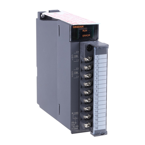
7 Setting and procedure for operation QE81WH 7.3 Name and function of each part Names and functions of parts of QE81WH are provided below. (1)LED Operation status of this module is displayed. (Refer to table.7.3-1.) (5) Push button (2) Current input terminals Use this button to Connect the current wire of insert a cable to the... - Page 76 7 Setting and procedure for operation QE81WH (1) Names and functions of LEDs The following describes names and functions of LEDs. Table 7.3-1 Names and functions of LEDs Name Color Role ON/OFF condition RUN LED Green Displays the Normal operation operation status OFF: 5V power discontinuity, watch dog...
-
Page 77: Attaching And Removing The Module
7 Setting and procedure for operation QE81WH 7.4 Attaching and removing the module 7.4.1 How to attach to the base unit (Q6□WRB) Base unit Insert it securely so that the protruding portion for fixing the module* does not come off of the module-fixing hole. -
Page 78: Wiring
7 Setting and procedure for operation QE81WH 7.5 Wiring 7.5.1 Precautions for wiring (1) Connect cables. For connecting voltage transformer and current transformer, refer to the corresponding wiring diagram. (2) For wiring, check with the wiring diagram and check phase wire system for the connecting circuit. - Page 79 7 Setting and procedure for operation QE81WH 7.5.2 How to connect wires (1) Follow the wiring diagram for external connection to QE81WH. (2) Use appropriate electric wires as described below. At the connection between the secondary terminal of current (EMU-CT***, EMU-CT***-A) sensor and , use twisted pair cable.
- Page 80 7 Setting and procedure for operation QE81WH 7.5.3 How to wire Follow the wiring diagram (Figure 7.5.3(1)-(a) ~ 7.5.3(2)-(c)) for external connection of QE81WH. (1) In the case using 5A current sensor. (a) Case of using EMU2-CT5 Power supply side 5A current sensor cable EMU2-CB-Q5A Current...
- Page 81 7 Setting and procedure for operation QE81WH (2) In the case using split-type current sensor. (a) Case of Three-phase 3-wire system Power supply side EMU-CT*** model current sensor (50/100/250/400/600) EMU-CT***-A model current sensor (50/100/250/400/600) Load side Figure 7.5.3(2)-(a) In the case of Three-phase 3-wire system (b) Case of Single-phase 2-wire system Power supply side EMU-CT*** model...
- Page 82 7 Setting and procedure for operation QE81WH (c) Case of Single-phase 3-wire system Power supply side EMU-CT*** model current sensor (50/100/250/400/600) EMU-CT***-A model current sensor (50/100/250/400/600) Load side Figure 7.5.3(2)-(c) In the case of Single-phase 3-wire 7 - 10...
- Page 83 7 Setting and procedure for operation QE81WH 7.5.3.1 Current circuit connection A dedicated current sensor (EMU-CT ***, EMU-CT ***-A, EMU2-CT5) is required to connect the current circuit. ■ How to attach EMU-CT5/CT50/CT100/CT250-A 1) Press the locking claw of the moving core, please open the moving core by removing the engagement (Figure 1).
- Page 84 7 Setting and procedure for operation QE81WH ■ How to attach EMU-CT400/CT600-A 1) Press the locking claw of the moving core, please open the moving core by removing the engagement (Figure 1). At this time, the hinge cover opens automatically. Before inserting the cable, check the symbols K and L to fit the current sensor in the correct direction.
- Page 85 7 Setting and procedure for operation QE81WH ■ How to attach EMU-CT50/CT100/CT250 Follow the procedure below to attach to the cable of the target circuit. Protective cover 1) Open the movable core, as shown in the figure on the right. Lift slowly the hooks located on both sides of the movable core, and detach them from the stopper.
- Page 86 7 Setting and procedure for operation QE81WH ■ How to attach EMU-CT400/CT600 Follow the procedure below to attach the cable to the target circuit. 1) Release the band 1) to the arrow direction (top), and Core cover detach the core cover. 2) Remove the terminal cover, and shift the secondary short switch into “short”.
- Page 87 7 Setting and procedure for operation QE81WH Follow the procedure below to attach the cable to the target circuit. 1) Slide the lock pin to the arrow Primary conductor (Cable) Lock pin direction. Clamp 2) Put the electric wire through the clamp, and close the clamp again.
- Page 88 7 Setting and procedure for operation QE81WH ◆Connecting 5 A current sensor and extension cable (separate) EMU2-CT5(0.5 m) EMU2-CB-T**MS(1 m to 10 m) EMU2-CB-Q5A(0.5 m) Supplementary ----------------------------------------------------------------------------------------------------------------------------- Cable extension for EMU2-CT5 is 10 m max. (Total cable length is 11 m max.) ...
-
Page 89: Setting From Gx Works2
7 Setting and procedure for operation QE81WH 7.6 Setting from GX Works2 This section explains setting from GX Works2 necessary to use QE81WH. Before performing this setting, install GX Works2 and connect the Management CPU with the PC using a USB cable. For details, refer to the manual of CPU module. - Page 90 7 Setting and procedure for operation QE81WH 7.6.2 Setting the intelligent function of the module switch Set the operation mode. (1)Setting procedure Open the “Switch Setting” window. Project window→[Intelligent Function Module]→Module name→[Switch Setting] Figure 7.6.2-1 Dialog box to set the intelligent function of the module switch Table 7.6.2-1 Setting the intelligent function of the module switch Item Description...
- Page 91 7 Setting and procedure for operation QE81WH 7.6.3 Parameter Setting Set the parameters. Setting parameters on the screen omits the parameter setting in a program. (1)Setting procedure Open the “Parameter” window. Project window→[Intelligent Function Module]→Module name→[Parameter] Figure 7.6.3-1 Dialog box to monitor all buffer memories (a case where the module is attached to the slot 0) (2)Double-click the item to change the setting, and input the setting value.
- Page 92 7 Setting and procedure for operation QE81WH Item Setting value Reference 1:single-phase 2-wire 2:single-phase 3-wire Phase wire system Section 6.2.1 3:three-phase 3-wire 0:Any setting 1:110V 2:220V 3:220/110V 4:440/110V Primary voltage Section 6.2.2 5:690/110V 6:1100/110V 7:2200/110V 8:3300/110V 9:6600/110V 0 V to 6600 V Primary voltage of VT Section 6.2.2 Secondary voltage of VT...
- Page 93 7 Setting and procedure for operation QE81WH 7.6.4 Auto Refresh This function transfers data in the buffer memory to specified devices. Programming of reading/writing data is unnecessary. (1)Setting procedure 1) Start “Auto Refresh” . Project window→[Intelligent Function Module]→Module name→[Auto Refresh] 2) Start “Auto Refresh”...
- Page 94 7 Setting and procedure for operation QE81WH 7.6.5 Setting function for integrated value This function is to set integrated value (electric energy (consumption, regeneration) and reactive energy (consumption lag)) to any value. If you want to clear integrated value, set it to 0. (1)Setting procedure 1) Start “Intelligent unit monitor”...
- Page 95 7 Setting and procedure for operation QE81WH 4) After checking that the Integrated value setting completion flag (Xn3) is in the ON status, turn off the integrated value setting request (Yn3). The integrated value setting completion flag (Xn3) is OFF, after detect the status is OFF. After detecting Integrated value setting request (Yn3) is in the OFF status, Integrated value setting completion flag (Xn3) turns to OFF.
- Page 96 7 Setting and procedure for operation QE81WH 7.6.6 Debugging program QE81WH provides a test function so that you can debug a program with no input of voltage or current. Pseudo-value can be stored into the buffer memory. For detailed explanation for the test function, refer to 4.2.5.
-
Page 97: Setting From Gx Developer
7 Setting and procedure for operation QE81WH 7.7 Setting from GX Developer This section explains setting from GX Developer necessary to use QE81WH. Before performing this setting, install GX Developer and connect the Management CPU with the PC using a USB cable. For details, refer to the manual of CPU module. - Page 98 7 Setting and procedure for operation QE81WH 7.7.2 Setting the intelligent function of the module switch (1) In the “I/O assignment” of 7.7.1, click the Switch setting button to display the dialog box of “I/O module, intelligent function module switch setting”. (2) The intelligent function module switch setting displays switches 1 to 5;...
- Page 99 7 Setting and procedure for operation QE81WH 7.7.3 Initial setting This section explains the setting of the operating condition for phase wire system, primary voltage, primary current, current demand time, and voltage demand time, primary voltage of VT, secondary voltage of VT, primary current of CT that are required for measurement. Once each value is set, these values will be stored in the nonvolatile memory of the module, so that reconfiguration is not needed.
- Page 100 7 Setting and procedure for operation QE81WH (2) Set the Buffer memory 1) In the dialog box to monitor all buffer memories, click the Device test button to display the Device test dialog box. 2) In the Word device / buffer memory, specify the module initial address and buffer address, and click the Set button to apply the setting.
- Page 101 7 Setting and procedure for operation QE81WH 7.7.4 Setting function for integrated value This function is to set integrated value ( electric energy ( consumption, regeneration ) and reactive energy (consumption lag) ) to any value. If you want to clear integrated value, set it to 0. (1) Check the current setting 1) From the “Online”...
- Page 102 7 Setting and procedure for operation QE81WH (2) Setting function for integrated value This function is to set integrated value (electric energy (consumption, regeneration) and reactive energy (consumption lag)) to any value. If you want to clear integrated value, set it to 0. 1) In the dialog box to monitor all buffer memories, click the Device test button to display the Device test dialog box.
- Page 103 7 Setting and procedure for operation QE81WH 7.7.5 Debugging program QE81WH provides a test function so that you can debug a program with no input of voltage or current. Pseudo-value can be stored into the buffer memory. For detailed explanation for the test function, refer to 4.2.5.
-
Page 104: Chapter 8: Programming
8: Programming QE81WH Chapter 8: Programming This chapter explains about programming for QE81WH. When you apply sample programs introduced in this chapter into the actual system, make sure to verify in advance that there is no problem with the target system control. Follow the procedure in Figure 8.1-1 to create a sample program using QE81WH. -
Page 105: System Configuration And Usage Conditions For Sample Program
8: Programming QE81WH 8.2 System configuration and usage conditions for sample program A sample program under the following system and the usage condition is shown below. (1) System configuration QY40 (Y20 to Y2F) QCPU QX40 (X10 to X1F) QE81WH (X/Y0 to X/YF) Figure 8.2-1 Sample system configuration using a sample program (2) Setting conditions for the intelligent function of the module switch Setting is as follows:... - Page 106 8: Programming QE81WH (c) Data acquisition clock setting - Output period of data acquisition clock : 1000 (1sec) (4) Before creating a program Before creating a program, attach QE81WH to the base unit, and connect it to external devices. Electric current sensor: EMU-CT250 Power supply side Load side Figure 8.2-2 Example of wiring using a sample program...
-
Page 107: Sample Programming
8: Programming QE81WH 8.3 Sample programming 8.3.1 Sample program when make the initial setting using GX Works2 or GX Developer. (1) List of devices Table 8.3.1-1 List of devices Device Function Device that stores latest error code Module ready Alarm 1 flag Alarm 2 flag Error flag QE81WH... - Page 108 8: Programming QE81WH (3) Sample program 1. Program for periodic energy function Instruct to measure the periodic electric energy 1 (Measurement is taken when X10 is ON.) Periodic electric energy 1 Module measurement flag READY Instruct to measure the periodic electric energy 2 (Measurement is taken when X10 is OFF.) Periodic electric energy 2 Module...
- Page 109 8: Programming QE81WH 8.3.2 Sample program when make the initial setting using sequence program. (1) List of devices Table 8.3.2-1 List of devices Device Function D0, D1 Device that stores Multiplier of electric energy D2, D3 Device that stores electric energy (consumption) D4, D5 Device that stores Average current D6, D7...
- Page 110 8: Programming QE81WH (2) List of buffer memories to be used Table 8.3.2-2 List of buffer memories to be used Device Description Setting Remarks value U0 \ G0 Phase wire system Three-phase 3-wire U0 \ G1 Primary voltage 220 V U0 \ G2 Primary current 250 A...
- Page 111 8: Programming QE81WH (3) Sample program 1. Initial setting program for QE81WH Phase Request of Module READY operating wire condition system setting Primary voltage Primary current Basic operating condition Current setting demand time Electric power demand time Primary voltage of VT Secondary voltage of VT Primary...
- Page 112 8: Programming QE81WH 2. Measured data acquisition program Multiplier of Module Output period of READY electric energy data acquisition clock Electric energy (consumption) Average current Average voltage Acquire each type of the measured values Active energy Reactive energy Power factor Frequency 3.
-
Page 113: Chapter 9: Troubleshooting 9-1
9 Troubleshooting QE81WH Chapter 9: Troubleshooting 9.1 List of error codes When the data are written to the CPU module from this module or when a reading error occurs, error codes will be stored into the following buffer memory. Table 9.1-1 Latest error code, storage destination upon error occurrence Latest error code Time of error occurrence Un\G3000... - Page 114 9 Troubleshooting QE81WH Error code Error Descriptions Action Reference (HEX) level Set primary voltage of VT within the range* of 0 to 6600 (V). Primary voltage of VT is set out of Section 100Dh However, this setting cannot set range. 6.2.2 0 (any setting) when primary voltage (Un¥G1) is 0.
- Page 115 9 Troubleshooting QE81WH 9.2 Troubleshooting 9.2.1 When “RUN” LED is turned off Table 9.2.1-1 When “RUN” LED is turned off Check item Action Reference Check that supply voltage of the power source is Section Is power source is supplied? within the rating. Calculate the consumption current of CPU Is capacity of the power source module, I/O module, and intelligent function...
- Page 116 9 Troubleshooting QE81WH 9.2.2 When “ERR.” LED is turned on or flashing (1) If it is ON Table 9.2.2-1 When “ERR.” LED is turned on Check item Action Reference Check latest error code (Un\G3000), and take a corrective action as described in section 9.1. After that, reset CPU module, and check whether it is Section turned on.
- Page 117 9 Troubleshooting QE81WH 9.2.3 If electric energy cannot be measured The following check has to be performed while current is flowing from the power source side to the load side. Table 9.2.3-1 If electric energy cannot be measured Check item Action Reference “MEA.”...
- Page 118 9 Troubleshooting QE81WH 9.2.4 If the electric current and voltage that are measured using this module do not match with the ones measured with other gauge Table 9.2.4-1 If current and voltage that are measured using this module do not match with the ones measured with other gauge Check item Action...
-
Page 119: Q&A
9 Troubleshooting QE81WH Q&A 9.3.1 General To what degree is the module durable against overvoltage and over current? Is external protective circuit required? Momentary* : Up to 2 times as high as rated voltage and 20 times as high as rated current. Continuous : Up to 1.1 times as high as rated voltage and rated current. - Page 120 9 Troubleshooting QE81WH If a load such as welding equipment exists, a current flows only for a short period (e.g. 2-cycle waveform of commercial frequency (50 Hz: 40 ms, 60 Hz: 33 ms)). Is accurate measurement possible? This module makes measurement with a sampling period of 4340 Hz (for both 50 Hz and 60 Hz).
- Page 121 9 Troubleshooting QE81WH What kind of time is “response time”? “Response time” is a period of time between a point of sudden change of voltage or current input and a point that an output (computation result) follows up to within± 10 % of input. Response time 100%...
- Page 122 9 Troubleshooting QE81WH 9.3.4 Q&A about Connection Does polarity exist in connection between a current sensor and the module? Yes, it does. Make connections so that secondary terminals of current sensor (k, l) and terminal symbols of module agree with each other. If polarity is incorrect, the current value is measurable, but the electric power and the electrical energy can not be measured correctly.
-
Page 123: Appendix 1: External Dimensions
Appendix QE81WH Appendix Appendix 1: External dimensions Unit [mm] Appendix - 1... -
Page 124: Appendix 2: Optional Devices
Appendix QE81WH Appendix 2: Optional devices (1)Specifications Split type current sensor ■ Item Specifications Model EMU-CT50 EMU-CT100 EMU-CT250 EMU-CT400 EMU-CT600 Rated primary current 50 A AC 100 A AC 250 A AC 400 A AC 600 A AC Rated secondary current 16.66 mA 33.33 mA 66.66 mA... - Page 125 Appendix QE81WH 5A current sensor ■ Item Specifications Model EMU2-CT5 EMU-CT5-A Rated primary current 5 A AC Rated secondary current 1.66 mA Rated burden 0.1 VA Maximum voltage 260 V AC 260 V AC (voltage to ground/line voltage) Ratio error ±1 %(5 % to 100 % of rating,R ≦10 Ω)...
- Page 126 Appendix QE81WH (2)External dimensions ■ Current sensor EMU-CT50, EMU-CT100, EMU-CT250 EMU-CT400, EMU-CT600 Core cover Protective cover M4 screw Split metal Hole for core surface fixing Secondary terminal (3×2) M4 screw Secondary short-circuit switch Binding band Stopper Movable Terminal Hook for fixing the movable core core cover...
- Page 127 Appendix QE81WH ■ Dedicated cable 5A current sensor cable EMU2-CB-Q5A Unit[mm] Extension cable (standard) EMU2-CB-T**M Model EMU2-CB-T1M EMU2-CB-T5M EMU2-CB-T10M Length 1000 mm 5000 mm 10000 mm Extension cable (separate) EMU2-CB-T**MS Model EMU2-CB-T1MS EMU2-CB-T5MS EMU2-CB-T10MS Length 1000 mm 5000 mm 10000 mm Appendix - 5...
-
Page 128: Appendix 3: Addition Or Change Of Functions
Appendix QE81WH Appendix 3: Addition or change of functions The following table lists functions added or changed to the QE81WH and GX Works2, serial number of compatible QE81WH, and software version of compatible GX Works2. serial number with Software version with Added or changed contents the QE81WH the GX Works2... - Page 129 Index 【5】 【M】 5A current sensor cable ·························· 7-14 Max./min. value hold function ··················· 4-12 【A】 Max./min. values clear completion flag (XnD) Alarm delay time ··································· 4-13 ···················································· 4-12, 5-4 Max./min. values clear request (YnD) ·· 4-12, 5-6 Alarm flag (XnA, XnB) ······················ 4-16, 5-3 Measured items ······································...
- Page 130 Warranty For using this product, please thoroughly read the following product warranty descriptions. 1. Gratis Warranty Period and Gratis Warranty Coverage If any failure or defect (hereinafter collectively called “failures”) for which our company is held responsible occurs on the product during the gratis warranty period, our company shall replace the product for free through the distributor at which you purchased the product or our service company.
- Page 131 Vte. Agua Santa 4211 Casilla 30-D (P.O. Box) Vina del Mar, Chile +56-32-2-320-600 Mitsubishi Electric Automation (China) Ltd. Mitsubishi Electric Automation Building, No.1386 Hongqiao Road, Shanghai, China 200336 +86-21-2322-3030 Mitsubishi Electric Automation (China) Ltd. 5/F,ONE INDIGO,20 Jiuxianqiao Road Chaoyang District,Beijing, China 100016...