
Related Manuals for Allen-Bradley Compact 5000


Summary of Contents for Allen-Bradley Compact 5000
- Page 1 User Manual Original Instructions Compact 5000 I/O Serial Module Catalog Number 5069-SERIAL...
- Page 2 Important User Information Read this document and the documents listed in the additional resources section about installation, configuration, and operation of this equipment before you install, configure, operate, or maintain this product. Users are required to familiarize themselves with installation and wiring instructions in addition to requirements of all applicable codes, laws, and standards.
-
Page 3: Table Of Contents
Power Compact 5000 I/O Serial Module......17 Configure Compact 5000 I/O Modules ......18 Connections . - Page 4 Chapter 3 Compact 5000 I/O Serial Module Purpose of the Module......... 23 General Module Features .
- Page 5 Module Status Indicator ........71 Compact 5000 I/O Serial Module Status Indicators....73...
- Page 6 Table of Contents Appendix D ASCII Conversion Tables ASCII Conversions ......... . 107 Index .
-
Page 7: Preface
Preface This manual describes how to use Compact 5000™ I/O Serial modules in Logix 5000™ systems. Make sure that you are familiar with the following: • Use of a Logix 5000™ controller • Use of an EtherNet/IP network, if the serial module is installed in a remote location that is accessible via the EtherNet/IP network. - Page 8 Preface To order paper copies of technical documentation, contact your local Allen-Bradley distributor or Rockwell Automation sales representative. Rockwell Automation Publication 5069-UM003A-EN-P - May 2018...
- Page 9 Preface Notes: Rockwell Automation Publication 5069-UM003A-EN-P - May 2018...
- Page 10 Preface Rockwell Automation Publication 5069-UM003A-EN-P - May 2018...
-
Page 11: Compact 5000 I/O Serial Module Overview
Add-On Profile to use the serial module. To find the Add-On Profile go to the Product Compatibility and Download Center (PCDC). For more information on how a Compact 5000 I/O serial module can function in a control system, see Chapter 2, Compact 5000 I/O Serial Module Operation in a Logix 5000 Control System. -
Page 12: About The Module
MOD Power bus and SA Pass system-side and field-side power across the internal circuitry of the I/O Power bus connectors modules in a Compact 5000 I/O system. The connectors are isolated from each other. Channel 0 Channel 0 isolated serial port. -
Page 13: Controller And Software Compatibility
• The manner in which you use the serial module affects controller compatibility. • You can use Compact 5000 I/O serial modules as local or remote I/O modules. IMPORTANT The serial module is not compatible with the 5069-AEN2TR. See the... -
Page 14: Local I/O Or Remote
Chapter 2 Compact 5000 I/O Serial Module Operation in a Logix 5000 Control System Local I/O or Remote You can use a Compact 5000 I/O Serial module as a local or remote I/O module. I/O Modules Local I/O Module When Compact 5000 I/O Serial module resides in the same system as the controller, it is a local I/O module. -
Page 15: Remote I/O Module
Remote Compact 5000 I/O modules are installed to the right of the adapter and exchange data across the remote system backplane. The data is exchanged with the controller over the EtherNet/IP network. IMPORTANT Compact 5000 I/O Serial modules can function as remote I/O modules in the following: • CompactLogix 5380 control systems •... -
Page 16: Ownership
• Stores configuration data for every module that it owns. • Can reside in a location that differs from the Compact 5000 I/O system. • Sends the I/O module configuration data to define module behavior and begin operation in the control system. -
Page 17: Power Compact 5000 I/O Serial Module
DC voltage. Power begins at the left-most device in the system and passes across the Compact 5000 I/O module internal circuitry via power buses, that is, a MOD power bus. The left-most device is either a controller or an EtherNet/IP adapter, depending on whether the Serial module is a local or remote I/O module. -
Page 18: Configure Compact 5000 I/O Modules
The owner-controller monitors its connection with a module. Any break in the connection, for example, the loss of power to the Compact 5000 I/O system, causes a fault. The Logix Designer application monitors the fault status tags to indicate when a fault occurs on a module. - Page 19 Compact 5000 I/O Serial Module Operation in a Logix 5000 Control System Chapter 2 Multiple Connections to One Serial Module Unlike other Compact 5000 I/O modules that make one connection to the owner-controller, the Compact 5000 I/O Serial module can have multiple connections based on how the module channels are configured.
- Page 20 Chapter 2 Compact 5000 I/O Serial Module Operation in a Logix 5000 Control System • Channel 0 = Generic ASCII, Channel 1 = Modbus Master - Three connections are made between the owner-controller and the module Table 2 shows the total number of connections for all protocol combinations.
-
Page 21: 5069-Arm And 5069-Fpd Modules
Compact 5000 I/O system. In this case, however, the required 5069-SERIAL module is not available for insertion. To install Compact 5000 I/O modules, you attach them to left-most device in the system. The node addresses increment as each module is installed. To make sure that the 5069-SERIAL module is installed in the correct location later, you install a 5069-ARM during initial system installation. -
Page 22: 5069-Fpd Field Potential Distributor
CH1 TXD CH1 RXD First SA Power Bus Second SA Power Bus For more information on how to power Compact 5000 I/O modules, see the following: • EtherNet/IP Communication Modules in Logix5000 Control Systems User Manual, publication ENET-UM004. • CompactLogix 5380 and Compact GuardLogix 5380 Controllers User Manual, publication 5069-UM001. -
Page 23: Purpose Of The Module
Modbus Master Data Exchange Modbus Slave Data Exchange Purpose of the Module The Compact 5000™ I/O Serial Module allows you to select two different communication modes to connect to serial devices in various communication mediums. For example, the RS-232C, RS-422, or RS-485. -
Page 24: Software Configurable
Chapter 3 Compact 5000 I/O Serial Module Features Software Configurable You use the Logix Designer application to configure the module, monitor system operation, and troubleshoot issues. You can also use the Logix Designer application to retrieve the following information from any module in the system: •... -
Page 25: Fault And Status Reporting
• Depending on the software version, you can set each channel value separately. Fault and Status Reporting The Compact 5000 I/O serial modules report fault and status data along with channel data. Fault and status data is reported in the following ways: • Logix Designer application •... -
Page 26: Module Inhibiting
Chapter 3 Compact 5000 I/O Serial Module Features Module Inhibiting Module inhibiting lets you indefinitely suspend a connection between an owner-controller and a serial module without removing the module from the configuration. This process lets you temporarily disable a module, such as to perform maintenance. -
Page 27: Electronic Keying
Compact 5000 I/O Serial Module Features Chapter 3 Electronic Keying Electronic Keying reduces the possibility that you use the wrong device in a control system. It compares the device that is defined in your project to the installed device. If keying fails, a fault occurs. These attributes are compared. -
Page 28: Status Indicators
Compact 5000 I/O Serial Module Features Status Indicators Each Compact 5000 I/O serial module has a status indicator on the front of the module that lets you check the health and operational status of a module. The status indicator displays vary for each module. -
Page 29: Common Module Functions
Compact 5000 I/O Serial Module Features Chapter 3 Common Module Functions The module supports the following terms, definitions, and parameters. Table 3 - Common Module Function Function Definition Available Options Baud Rate The communication speed of each channel. • 9600 •... -
Page 30: Control Line Menu
Chapter 3 Compact 5000 I/O Serial Module Features Control Line Menu When you are required to connect to a dial up modem, see Table 4 explaining the duplex setting in the serial port. Table 4 - Control Line Menu Modem... -
Page 31: Data Exchange
Compact 5000 I/O Serial Module Features Chapter 3 Data Exchange Generic ASCII Data Exchange The following illustrations show the different data exchanges using the serial module. Data Sent with the Serial Port Data is sent out of the serial port using the following steps: 1. -
Page 32: Generic Ascii Transmit Functions
Chapter 3 Compact 5000 I/O Serial Module Features Generic ASCII Transmit Functions In Generic ASCII mode, you can define any kind of data to be transmitted to communicate to serial devices. Some examples are barcode scanners, dial up modems, serial printers, temperature controllers, and so on. -
Page 33: Generic Ascii Receive Functions
Compact 5000 I/O Serial Module Features Chapter 3 Generic ASCII Receive Functions Table 6 - Generic ASCII Receive Functions Swap Mode Swapping is done before the module sends output data to the Serial Port • No Change (default) or after the module receives input data from the Serial Port. - Page 34 Chapter 3 Compact 5000 I/O Serial Module Features Generic ASCII Receive Methods When receiving the ASCII packet based on a fixed number of characters, the number of characters is configured in the Read Buffer Size parameter. • For this method, configure Termination Mode for Ignore End Delimiter.
-
Page 35: Data Received From The Serial Port In Immediate Mode
Compact 5000 I/O Serial Module Features Chapter 3 Data Received from the Serial Port in Immediate Mode After the serial port receives data, it processes the data using the following steps. 1. The serial module receives the packet. 2. If any of the following conditions occur, the serial module creates a record. -
Page 36: Data Received From The Serial Port In Master/Slave
Chapter 3 Compact 5000 I/O Serial Module Features Data Received from the Serial Port in Master/Slave Handshake Mode The serial port works in a handshake mode using the following steps. 1. The serial module receives the packet. 2. If any of the following conditions occur, the serial module creates a record. -
Page 37: Modbus Master Data Exchange
• Write - the Modbus Master writes data to the Modbus Slave. Exchange • Read - the Modbus Master reads data from the Modbus Slave. The Compact 5000 I/O Serial Module can get Modbus Data from Produced/Consumed Data command, every RPI. Modbus Master Write Command... -
Page 38: Modbus Master Read Command
Chapter 3 Compact 5000 I/O Serial Module Features Modbus Master Read Command 5069-Serial Modbus Master ControlLogix 5580/CompactLogix 5380 Config Tag Command List Table Command List Config Data Consumed Output Tag Output Command List Interpreter Data Data to Slave Consumed Data... -
Page 39: Modbus Slave Data Exchange
Compact 5000 I/O Serial Module Features Chapter 3 Modbus Slave Data Exchange For the Modbus Slave data exchange, the following definitions apply: • Write - the Controller and Modbus Master can write data to the Modbus Slave. • Read - the Modbus Master reads data from the Modbus Slave. -
Page 40: Modbus Slave Read Command
Chapter 3 Compact 5000 I/O Serial Module Features Modbus Slave Read Command ControlLogix 5580/CompactLogix 5380 5069-Serial Modbus Slave Config Tag Virtual Device Application Mapping Table Config Data Output Tag Output Consumed Mapping Table Data to Master Data Consumed Data Produced... -
Page 41: Modbus Master Functions
Compact 5000 I/O Serial Module Features Chapter 3 Modbus Master Functions In Modbus mode, the serial module supports both Modbus ASCII and Modbus RTU to connect to Modbus enabled devices like flowmeters, power meters or remote RTU talking on Modbus RTU/ASCII. -
Page 42: Modbus Slave Functions
Chapter 3 Compact 5000 I/O Serial Module Features Table 9 - Inter-frame Timeout Minimum Values (11 Bit) Baud Rate Default Value 1Byte (11Bit) 3.5t (11Bit) Legal Range (11Bit) 1200 64000 9166.667 32083.333 32000…65535000 (us) 2400 32000 4583.333 16041.667 16000…65535000 (us) -
Page 43: Before You Begin
You must complete the following tasks before you can configure the module: 1. Create a Logix Designer application project. 2. If you use the Compact 5000 I/O serial module as remote I/O module, add a Compact 5000 I/O EtherNet/IP adapter to the project. -
Page 44: Create A New Module
Create a New Module After you create a Logix Designer application project and, if necessary, add a Compact 5000 I/O EtherNet/IP adapter to the project, complete the following steps to create a module in the project. There are two methods to add modules to your Logix Designer application project. - Page 45 Configure Compact 5000 I/O Serial Module Chapter 4 3. At the Select Module Type window, click Create to add the discovered module to your project. 4. At the New Module window, configure the module properties and click OK. Rockwell Automation Publication 5069-UM003A-EN-P - May 2018...
- Page 46 Chapter 4 Configure Compact 5000 I/O Serial Module 5. At the warning dialog box, click Yes. TIP If you inhibit the module connection, you must remember to uninhibit the connection later. 6. Close the Select Module Type dialog box. To add additional local I/O modules with this method, complete one of the following: •...
-
Page 47: New Local I/O Modules
Configure Compact 5000 I/O Serial Module Chapter 4 New Local I/O Modules To use the New Module method with local I/O modules, complete these steps. TIP This example shows how to add a local I/O module when the Logix Designer application project is offline. - Page 48 Chapter 4 Configure Compact 5000 I/O Serial Module 2. Select the module and click create. 3. At the New Module window, configure the module properties and click OK. To add additional local I/O modules with this method, complete one of the following: •...
-
Page 49: Discover Remote I/O Modules
To use the Discover Modules method with remote I/O modules, complete these steps. 1. Go online with your Logix Designer application. The project must include at Compact 5000 I/O EtherNet/IP adapter. 2. Right-click the Compact 5000 I/O EtherNet/IP adapter and choose Discover Modules. - Page 50 Chapter 4 Configure Compact 5000 I/O Serial Module 4. At the New Module window, configure the module properties and click 5. At the warning dialog box, make sure that Inhibit module connection is selected and click Yes. 6. Close the Select Module Type dialog box.
-
Page 51: New Remote I/O Module
Configure Compact 5000 I/O Serial Module Chapter 4 New Remote I/O Module To use the New Module method with remote I/O modules, complete these steps. TIP This example shows how to add a local I/O module when the Logix Designer application project is offline. - Page 52 Chapter 4 Configure Compact 5000 I/O Serial Module 2. Select the module and click Create. The New Module dialog box appears with a list of categories on the left side. The number and type of categories varies by module type.
- Page 53 Configure Compact 5000 I/O Serial Module Chapter 4 3. You can click OK to use the default configuration as shown or edit the module configuration. The rest of this chapter describes how to edit module configuration categories. To add additional remote I/O modules with this method, complete one of the following: •...
-
Page 54: Edit The Module Configuration
New Module dialog box. Some new module configuration categories apply to all Compact 5000 I/O digital modules. Some categories are specific to the module type. The following categories apply to all Compact 5000 I/O modules and are described in this section. •... - Page 55 Configure Compact 5000 I/O Serial Module Chapter 4 Module Definition Module Definition parameters are available on the General tab of the Module Properties dialog box in the Logix Designer application project. The module definition can only be edited during offline mode.
- Page 56 Chapter 4 Configure Compact 5000 I/O Serial Module Table 11 describes the parameters that are available on the Module Definition dialog box. Table 11 - Module Definition Parameters Parameter Definition Available Choices Series Module hardware series Module-specific Revision Module firmware revision, including major and minor revision levels...
- Page 57 Configure Compact 5000 I/O Serial Module Chapter 4 Depending on your parameter choice for one channel, you can have additional configurable parameters. The parameters are available on the left-side corresponding pages. Depending on what you choose, you can have additional parameters.
- Page 58 Chapter 4 Configure Compact 5000 I/O Serial Module Table 13 - Master Command List Modbus Master Parameters Parameter Definition Communication Method Communication Method: • Disabled • Continuous - sending the command based on the Poll interval value. • Conditional - only for Write command and triggered when the write value has changed.
- Page 59 Configure Compact 5000 I/O Serial Module Chapter 4 Master Command List Limitations • A maximum of 50 commands can be created. The commands are subject to available connection memory. • Each Modbus Master supports up to two data connections. • Each data connection supports a max of 446 bytes of read data and 482 bytes of write data.
- Page 60 Chapter 4 Configure Compact 5000 I/O Serial Module Figure 10 - Modbus Slave Module Definition Parameters IMPORTANT On the module definition screen, you will see two options at the top for moving the commands up and down. If either of these buttons are used, make sure the user program is adjusted to reflect the new location of the command or the program will show and error.
- Page 61 Configure Compact 5000 I/O Serial Module Chapter 4 Data Index This value indicates the offset of the register type address in the controller tags that allows the serial module to read or write the required data to or from the controller.
- Page 62 Chapter 4 Configure Compact 5000 I/O Serial Module Modbus Slave Address Table Limits • Up to 30 data point ranges can be created, subject to available memory: – 200 byte maximum of Holding registers (up to 100 INTs or 50 REALs) –...
-
Page 63: Connection Category
Configure Compact 5000 I/O Serial Module Chapter 4 Connection Category The Connection category lets you complete the following tasks: • Set the RPI rate. For more information on the RPI, see on page • Inhibit the module. For more information on inhibit the module, see page •... - Page 64 Chapter 4 Configure Compact 5000 I/O Serial Module Generic ASCII Figure 12 - Generic ASCII Connection Figure 13 - Generic ASCII Module Info Figure 14…Figure 16 show the communication port that defines the baud rate, serial media setting, and receive and transmit settings.
- Page 65 Configure Compact 5000 I/O Serial Module Chapter 4 Figure 15 - Generic ASCII Receive For more information, see Generic ASCII Receive Functions on page 33 Figure 16 - Generic ASCII Transmit For more information, see Generic ASCII Transmit Functions on page 32...
- Page 66 Chapter 4 Configure Compact 5000 I/O Serial Module Modbus Master and Slave Figure 17 - Modbus Master and Slave Connection Figure 18 - Channel 0 and Channel 1 Parameters For module function definitions, see Common Module Functions on page Rockwell Automation Publication 5069-UM003A-EN-P - May 2018...
- Page 67 Configure Compact 5000 I/O Serial Module Chapter 4 Figure 19 Figure 20 show the detailed communication settings for Modbus Master and Modbus Slave. Figure 19 - Modbus Master Channel Parameters For Modbus Master function definitions, see Modbus Master Functions on...
-
Page 68: Module Info Category
Chapter 4 Configure Compact 5000 I/O Serial Module Module Info Category The Module Info category displays module and status information about the module when the project is online. You can use this category to complete the following: • Determine the identity of the module. -
Page 69: View The Module Tags
Configure Compact 5000 I/O Serial Module Chapter 4 View the Module Tags When you create a module, the Logix Designer application creates a set of tags that you can view in the Tag Editor. Each configured feature on your module has a distinct tag that is available for use in the controller program logic. -
Page 70: Rockwell Automation Publication 5069-Um003A-En-P - May
Chapter 4 Configure Compact 5000 I/O Serial Module Notes: Rockwell Automation Publication 5069-UM003A-EN-P - May 2018... -
Page 71: Troubleshoot Your Module
Compact 5000 I/O Serial modules. Module Status Indicator Table 15 describes the Module (MOD) Status indicator on Compact 5000 I/ O Serial modules Table 15 - Module Status Indicator - Compact 5000 I/O Module Indicator State Description Recommended Action The module is not powered. - Page 72 Chapter 5 Troubleshoot Your Module Table 15 - Module Status Indicator - Compact 5000 I/O Module Indicator State Description Recommended Action Flashing green The following conditions exist: Complete the following: • Both channels are disabled. • Troubleshoot your Logix Designer application to determine what is •...
-
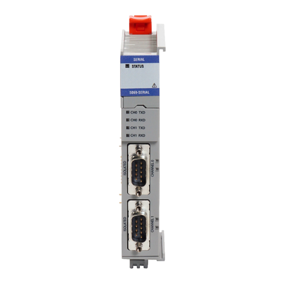
Page 73: Compact 5000 I/O Serial Module Status Indicators
Troubleshoot Your Module Chapter 5 Compact 5000 I/O Serial Figure 21 shows the Compact 5000 I/O serial Module Status indicators. Module Status Indicators Figure 21 - Compact 5000 I/O Serial Status Indicators SERIAL Module Status Indicator 5069-SERIAL CH0 TXD CH0 TXD Indicator... - Page 74 Chapter 5 Troubleshoot Your Module Notes: Rockwell Automation Publication 5069-UM003A-EN-P - May 2018...
-
Page 75: Module Tags
• 1 = slot number • I0 = tag type (input) and channel number (0) – The possible Compact 5000 I/O serial tag types are I (input) and O (output) – The possible channels are channel 0 and channel 1 •... -
Page 76: Modbus Master Name Conventions
• 1 = slot number • I00 = tag type (input), channel number (0), number of connections (0) – The possible Compact 5000 I/O serial tag types are I (input) and O (output) – The possible channels are channel 0 and channel 1 –... -
Page 77: Channel Configured Generic Ascii Tags
Module Tags Appendix A Channel Configured Generic This section describes the tags that are created when you choose the Generic ASCII option for a channel in the module definition dialog box as shown in ASCII Tags the following graphics. Rockwell Automation Publication 5069-UM003A-EN-P - May 2018... -
Page 78: Channel Configured For Generic Ascii
Appendix A Module Tags Channel Configured for Input Tags Generic ASCII The following image shows the tags that are described in the following table. Table 17 describes the input tags of channel 1 configured to the Generic ASCII. Rockwell Automation Publication 5069-UM003A-EN-P - May 2018... - Page 79 Module Tags Appendix A Table 17 - Generic ASCII Input Module Tags Name Data Type Definition Valid Values Ix.RunMode BOOL Channel’s operating state • 0 = Idle • 1 = Run Ix.ConnectionFaulted BOOL Indicates if a connection is running. • 0 = Connection running •...
- Page 80 Appendix A Module Tags Table 17 - Generic ASCII Input Module Tags Name Data Type Definition Valid Values Ix.ASCII.FramingError BOOL Indicates whether an error in framing has occurred. • 0 = Non-occurrence • 1 = Occurrence Ix.ASCII.BufferOverRun BOOL Indicates whether a buffer overrun has occurred. •...
-
Page 81: Output Tags
Module Tags Appendix A Output Tags This screen capture shows the tags that are described in the following table. Table 18 describes the output tags of channel 1 configured to the Generic ASCII Table 18 - Generic ASCII Output Module Tags Name Data Type Definition... -
Page 82: Channel Configured For Modbus Master
Appendix A Module Tags Channel Configured for This screen capture shows the tags that are described in the following tables. Modbus Master Input Tags In the following table, the in the tag names represents the channel number because the module has two channels, and both channels support the use of Modbus Master. - Page 83 Module Tags Appendix A Table 19 - Modbus Master Input Tags Name Data Type Definition Valid Values Ixx.DiagnosticSequenceCount SINT Increments for each time a distinct diagnostic condition is detected, -128…127 and when a distinct diagnostic condition transitions from detected The value of 0 is skipped except during to not detected.
-
Page 84: Output Tags
Appendix A Module Tags Table 19 - Modbus Master Input Tags Name Data Type Definition Valid Values Ixx.Command.yy.SlaveErrorCode SINT Indicates if a slave error code has occurred. • 0 = Non-occurrence • IMPORTANT: A slave error code is not equal to an exception •... -
Page 85: Channel Configured For Modbus Slave
Module Tags Appendix A Channel Configured for This screen capture shows the tags that are described in the following tables. Modbus Slave Rockwell Automation Publication 5069-UM003A-EN-P - May 2018... -
Page 86: Input Tags
Appendix A Module Tags Input Tags In the following table, the in the tag names represents the channel number because the module has two channels, and both channels support the use of Modbus Slave. Table 21 - Modbus Slave Input Tags Name Data Type Definition... -
Page 87: Output Tags
Module Tags Appendix A Output Tags In the following table, the in the tag name represents the channel number because the module has two channels, and both channels support the use of Modbus Slave. Table 22 - Modbus Slave Output Tags Name Data Type Definition... - Page 88 Appendix A Module Tags Notes: Rockwell Automation Publication 5069-UM003A-EN-P - May 2018...
-
Page 89: Master Command List
Appendix Master Command List Topic Page Read Coil Status (Function Code 01) Read Input Status (Function Code 02) Read Holding Registers (Function Code 03) Read Input Registers (Function Code 04) Force Single Coil (Function Code 05) Preset Single Register (Function Code 06) Force Multiple Coils (Function Code 15) Preset Multiple Registers (Function Code 16) Master Command List... - Page 90 Appendix B Master Command List Response An example response to Read Coil Status is as shown in the following table. The data is packed one bit for each coil. The response includes the slave address, function code, quantity of data characters, the data characters, and error checking.
-
Page 91: Read Input Status (Function Code 02)
Master Command List Appendix B Read Input Status (Function Code 02) Query This function allows you to obtain the ON/OFF status of discrete inputs (Modbus 1x range) in the addressed slave. PC Broadcast mode is not supported with this function code. In addition to the slave address and function fields, the message requires that the information field contain the initial input address to be read (Starting Address) and the number of locations that are interrogated to obtain status data. -
Page 92: Read Holding Registers (Function Code 03)
Appendix B Master Command List Because the slave interface device is serviced at the end of a controller's scan, the data reflect input status at the end of the scan. Some slaves limit the quantity of inputs provided each scan; thus, for large coil quantities, multiple PC transactions must be made using coil status for sequential scans. -
Page 93: Read Input Registers (Function Code 04)
Master Command List Appendix B Response The addressed slave responds with its address and the function code, followed by the information field. The information field contains 1 byte describing the quantity of data bytes to be returned. The contents of the registers requested (DATA) are two bytes each, with the binary content right justified within each pair of characters. -
Page 94: Force Single Coil (Function Code 05)
Appendix B Master Command List Response The addressed slave responds with its address and the function code followed by the information field. The information field contains 1 byte describing the quantity of data bytes to be returned. The contents of the registers requested (DATA) are 2 bytes each, with the binary content right justified within each pair of characters. - Page 95 Master Command List Appendix B The use of slave address 00 (Broadcast Mode) forces all attached slaves to modify the desired coil. TIP Functions 5, 6, 15, and 16 are the only messages that are recognized as valid for broadcast. The following example is a request to slave number 11 to turn ON coil 0173.
-
Page 96: Preset Single Register (Function Code 06)
Appendix B Master Command List Preset Single Register (Function Code 06) Query This Function Code allows you to modify the contents of a Modbus 4x range in the slave. This code writes to one register only. Any holding register that exists within the controller can have its contents changed by this message. -
Page 97: Force Multiple Coils (Function Code 15)
Master Command List Appendix B Force Multiple Coils (Function Code 15) Query This function forces each coil (Modbus 0x range) in a consecutive block of coils to a desired ON or OFF state. Any coil that exists within the controller can be forced to either state (ON or OFF). -
Page 98: Preset Multiple Registers (Function Code 16)
Appendix B Master Command List Preset Multiple Registers (Function Code 16) Query The Function Code allows you to modify the contents of a Modbus 4x range in the slave. This writes up to 125 registers at a time. Since the controller is actively scanning, it can alter the content of any holding register at any time. -
Page 99: Programming Example
Appendix Programming Example Generic ASCII Sample Code The following images show sample code for Generic ASCII Transmit data and Generic ASCII Receive data. Configuration Generic ASCII Transmit and Receive Channel Configurations The following image shows the Generic ASCII Transmit Configuration. The following image shows the Generic ASCII Receive Configuration Rockwell Automation Publication 5069-UM003A-EN-P - May 2018... - Page 100 Appendix C Programming Example To test the ASCII capabilities by transmitting out Channel 0 and receiving in Channel 1, connect the two serial ports together using a 1761-CBL-AC00 cable. On the Module Properties Channel screens, verify that both channels are configured identically for RS-232C.
- Page 101 Programming Example Appendix C Rockwell Automation Publication 5069-UM003A-EN-P - May 2018...
-
Page 102: Modbus Sample Code Configuration
Appendix C Programming Example Modbus Sample Code The following images show sample code configuration for Modbus Master and Modbus Slave communication. Configuration Modbus Master Command List Modbus Slave Address Mapping Table Modbus Sample Code Configuration Example To test the Modbus capabilities by configuring Channel 0 for Master and Channel 1 for Slave, connect the two serial ports together using a 1761-CBL- AC00 cable. -
Page 103: Modbus Master Sample Code
Programming Example Appendix C Modbus Master Sample Code Modbus Slave Sample Code Rockwell Automation Publication 5069-UM003A-EN-P - May 2018... - Page 104 Appendix C Programming Example Rockwell Automation Publication 5069-UM003A-EN-P - May 2018...
- Page 105 Appendix ASCII Conversion Tables ASCII Conversions The following table defines the conversions between decimal, octal, hex, and binary values and the ASCII character or control associated with that value. Table 23 - ASCII Conversions Decimal Octal Binary ASCII Character or Control Decimal Octal Binary...
- Page 106 Appendix D ASCII Conversion Tables Table 23 - ASCII Conversions (continued) Decimal Octal Binary ASCII Character or Control Decimal Octal Binary ASCII Character or Control 0110101 1011000 0110110 1011001 0110111 1011010 0111000 1011011 0111001 1011100 0111010 1011101 0111011 1011110 0111100 <...
-
Page 107: Ascii Conversions
Index Numerics function codes 91 force multiple coils 99 5069-ARM address reserve module 21 force single coil 96 5069-FPD field potential distributor 22 preset single register 98 read coil status 91 read holding registers 94 read input registers 95 read input status 93 access module tags 76 additional resources 7 ASCII conversion tables 107... -
Page 108: Index
Index Power Compact 5000 I/O Serial Module 17 field-side power 17 system-side power 17 programming example 101 remote I/O module 15 serial module diagram 12 parts 12 serial module diagram 12 serial module status indicators 73 software compatibility 13 software configurable 24... - Page 110 Rockwell Automation maintains current product environmental information on its website at http://www.rockwellautomation.com/rockwellautomation/about-us/sustainability-ethics/product-environmental-compliance.page. Allen-Bradley, Compact 5000, CompactLogix, CompactLogix 5380, ControlLogix, ControlLogix 5580, GuardLogix 5380, GuardLogix 5580, Logix 5000, Rockwell Software, Rockwell Automation, and Studio 5000 are trademarks of Rockwell Automation, Inc.