Table of Contents
Table of Contents

Related Manuals for Allen-Bradley PowerMonitor 500


Summary of Contents for Allen-Bradley PowerMonitor 500
- Page 1 User Manual Original Instructions PowerMonitor 500 Unit Catalog Numbers 1420-V1, 1420-V1P, 1420-V1A, 1420-V1-ENT, 1420-V1-485, 1420-V1P-ENT, 1420-V1P-485, 1420-V1A- ENT, 1420-V1A-485, 1420-V2, 1420-V2P, 1420-V2A, 1420-V2-ENT, 1420-V2-485, 1420-V2P-ENT, 1420-V2P-485, 1420- V2A-ENT, 1420-V2A-485...
- Page 2 Important User Information Read this document and the documents listed in the additional resources section about installation, configuration, and operation of this equipment before you install, configure, operate, or maintain this product. Users are required to familiarize themselves with installation and wiring instructions in addition to requirements of all applicable codes, laws, and standards.
- Page 3 Summary of Changes This manual contains new and updated information as indicated in the following table New and Updated This table contains the changes made to this revision. Information Topic Page Updated wiring diagrams in Chapter 2. 19…22 Added CIP message examples to Appendix C 75…82 Rockwell Automation Publication 1420-UM001E-EN-P - March 2016...
- Page 4 Summary of Changes Notes: Rockwell Automation Publication 1420-UM001E-EN-P - March 2016...
-
Page 5: Table Of Contents
PowerMonitor 500 Unit Overview About the PowerMonitor 500 Unit ....... . . 9 PowerMonitor 500 Features and Functions . - Page 6 Table of Contents Index ..............85 Rockwell Automation Publication 1420-UM001E-EN-P - March 2016...
-
Page 7: About This Manual
Catalog Number Explanation 1420 -485 Bulletin Number Voltage Auxiliary Optional Comms 1420 - PowerMonitor 500 V1 - 240V AC V-LL P - Pulse (Digital) Output 485 - Serial RS-232, 120V AC V-LN/208V AC V-LL A - Analog Output RS-485, Modbus RTU... -
Page 8: Additional Resources
Provides declarations of conformity, certificates, and other certification details. You can view or download publications at http://www.rockwellautomation.com/literature/. To order paper copies of technical documentation, contact your local Allen-Bradley distributor or Rockwell Automation sales representative. Rockwell Automation Publication 1420-UM001E-EN-P - March 2016... -
Page 9: About The Powermonitor 500 Unit
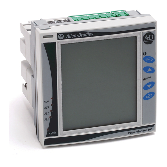
Chapter PowerMonitor 500 Unit Overview About the PowerMonitor 500 The PowerMonitor™ 500 unit is an AC power monitor with a built-in advanced configuration system and LCD data display. The unit is designed for Unit measurement of electrical parameters in various three-phase, single-phase (2-wire European), and split-phase (3-wire North American single phase) circuits. -
Page 10: Powermonitor 500 Features And Functions
Chapter 1 PowerMonitor 500 Unit Overview PowerMonitor 500 Features The power monitor connects to your three-phase, split-phase (3-wire North American single phase), or single-phase (2-wire European) AC power system and Functions directly or through instrument transformers (PTs and CTs). It converts instantaneous voltage and current values to digital values, and uses the resulting digital values in calculations of voltage, current, power, energy, and demand. -
Page 11: Front Panel Features
PowerMonitor 500 Unit Overview Chapter 1 Front Panel Features This section describes the front panel of the unit. Front Panel Indicators and Control Buttons The buttons are enhanced touch buttons. The touch icon turns on each time a button is pressed. We recommend using your forefinger to activate the touch buttons. - Page 12 Certain buttons have two functions. To access the second function, press and hold the button for more than 2 seconds. Displays PowerMonitor 500 information screens, which provide reference standards, firmware revision, and year of manufacture. Resets the max (maximum) of the displayed variables. You must press Program/ select to confirm the reset.
-
Page 13: Display Features
PowerMonitor 500 Unit Overview Chapter 1 Display Features Figure 2 - Features Display Item Description Phase displacement indicator: inductive L, -L, or capacitive C, -C. The sign is based on the direction of real power flow. Positive = consuming power, negative = generating power. -
Page 14: Selecting Data To Display
Chapter 1 PowerMonitor 500 Unit Overview Selecting Data to Display Table 1 Table 2 provide a guide to navigation through the metering data displays available on the front panel display. Row 1…Row 5 indicate the rows of the display (see Figure 2 on page 13). - Page 15 PowerMonitor 500 Unit Overview Chapter 1 To access information pages, press and hold for more than 2 seconds, then press to select information items, as shown in Table After a period of inactivity, the information pages close, and the display returns to the default screen.
- Page 16 Chapter 1 PowerMonitor 500 Unit Overview Figure 3 are examples of how the information pages are displayed. Figure 3 - Information Page 2 Row 1 Row 2 Row 3 Row 4 Row 5 PowerMonitor 500 Figure 4 - Information Page 15...
-
Page 17: Installation
Chapter Installation and Wiring Installation This section shows the dimensions of the unit for installation in a panel. Figure 5 - Base Unit Dimensions 89.97 mm 96.00 mm (3.54 in.) (3.78 in.) 93.00 mm (3.66 in.) 96.00 mm (3.78 in.) 20.20 mm 29.70 mm (0.80 in.) - Page 18 Chapter 2 Installation and Wiring Figure 8 - Installation in Panel Figure 9 - Rear View of Unit Showing Wiring Terminals Power Supply Rockwell Automation Publication 1420-UM001E-EN-P - March 2016...
-
Page 19: Wiring Diagrams
Installation and Wiring Chapter 2 Wiring Diagrams The PowerMonitor™ 500 unit can monitor various three-phase, single-phase, and split-phase circuits. Select the voltage connections, current wiring, and system metering mode to match the configuration of the circuit being monitored. Table 4 provides a key for you to select the proper wiring diagrams and system metering modes. - Page 20 Chapter 2 Installation and Wiring These diagrams are simplified. Wiring of the power monitor must comply with all applicable codes, standards, and regulations. Protect voltage and control power wiring with suitable overcurrent protection. Connect current transformer (CT) secondary wiring through a suitable shorting terminal block. In these diagrams, ‘balanced load’...
- Page 21 Installation and Wiring Chapter 2 Figure 13 - 3-phase, 3-wire Delta, Unbalanced Load Meter Configuration: System = 3P Line Line PM 500 PT 1 PM 500 (VT 1) Fuse Fuse Fuse Fuse Fuse Fuse PT 3 (VT 3) Ground Shorting Shorting terminal block terminal block...
- Page 22 Provide overcurrent protection that is sized to protect the wiring. Apply supply power only after all wiring connections are made to the unit. Figure 17 - Supply Power 120/240V AC 50/60Hz, or 120/240V DC PowerMonitor 500 F = 250V (T) 630 mA Rockwell Automation Publication 1420-UM001E-EN-P - March 2016...
- Page 23 Installation and Wiring Chapter 2 Factory Installed Option Wiring Figure 18 - Pulse (digital) Outputs (P option) Out 1 Out 2 Out 1 Out 2 Figure 19 - Analog Outputs (A option) Analog 20 mA DC Out 1 Out 2 Figure 20 - Serial RS-485 and RS-232 Communication Wiring (485 option) RS-485 Port RS-232 Port...
- Page 24 Ethernet Network Switch Uplink to LAN PowerMonitor 500 PowerMonitor 500 The PowerMonitor 500 unit connects to industry-standard Ethernet hubs and switches by using standard CAT-5 UTP (unshielded twisted-pair) cables with RJ45 connectors. Table 5 shows the cable and connector pin assignments.
-
Page 25: Configure With The Display
Chapter Unit Configuration Configure with the Display The PowerMonitor™ 500 unit provides menu-based configuration (programming) by using its front panel display. The programming menus let you select parameters to edit, select digits within parameters, and increase or decrease the value of each digit. Place the unit in Programming mode by pressing Program/select (8) for about 2 seconds. - Page 26 Chapter 3 Unit Configuration Figure 22 - Front Panel Display Table 6 - Front Panel Display Descriptions Display Item Description Navigating Menus Editing a Menu Programming mode indicator Indicates programming mode. Programming menu page Identifies the current programming menu page. See the programming flowchart that begins on page Editing mode indicator Does not appear.
- Page 27 2 minutes, the power monitor exits Programming mode without saving any changes. You can make programming changes by using the PowerMonitor 500 software. Edit Decimal Point and Multiplier When the cursor is beneath the last digit on the left, pressing Exit (6) lets you change the decimal point and the multiplier (9) (k or M).
-
Page 28: Configuration Flowchart
Chapter 3 Unit Configuration Configuration Flowchart The following flowchart shows the configuration menus and submenus that are accessed through the display. To navigate through the menu pages, use the up and down arrows. To enter Edit mode or to access a submenu, press the Program/ select button. - Page 29 Unit Configuration Chapter 3 • 80 DMD: This function lets you select the calculation method of the DMD/AVG value of the selected variable. – 81 TYPE: select the type of Calculation mode to be used for the DMD/AVG calculation. FIXED: The instrument calculates the AVG/DMD value of the measured variable over the selected interval, updates the AVG/DMD value at the end of the interval, then resets and starts a new...
- Page 30 Chapter 3 Unit Configuration • 120 RS232-485: User settings for the RS-232 and RS-485 serial communication ports. • 130 ETHERNET: User settings for the Ethernet communication port. • 150 VIRT AL 1: This virtual alarm function lets you www.xxx.yyy.zzz -IP ADDRESS set the alarm parameters.
- Page 31 Unit Configuration Chapter 3 • 210 AN OUT 1: User programming of the analog outputs (0…20 mA). List of available – 211 VARIABLES: selects the variable to be variables retransmitted with the analog output. – 212 MIN OUTPUT: sets the value that is expressed as % of the output range (0…20 mA) that corresponds to the minimum measured value.
-
Page 32: Digital Filtering Operation
Chapter 3 Unit Configuration Digital Filtering Operation Digital filtering smooths out the display of fluctuating values. The parameter FILTER S defines the operating range of the filter. This operating range is represented as a yellow band (each small square is one digit). While the measured value (red curve in Figure 23) is within this band, the filter is active. - Page 33 Unit Configuration Chapter 3 The FILTER S parameter, which represents the action range of the digital filter, is programmed to a value that must be slightly higher than the percentage amplitude of the fluctuation, for example, 1.0%. FILTER CO: if the new value that is measured by the instrument is within the action range of the filter, the new displayed value is obtained by adding algebraically the previous value to the variation divided by the filtering coefficient.
- Page 34 Chapter 3 Unit Configuration FILTER CO: if the new value that is acquired by the unit is within the filtering action range, the new displayed value is obtained by adding algebraically the previous value to the variation divided by the filtering coefficient. As a consequence, a value higher than this coefficient implies a higher settling time and therefore better stability.
-
Page 35: Analog Output Configuration Examples
Unit Configuration Chapter 3 Analog Output Configuration These examples apply to units with catalog numbers 1420-V1A and 1420-V2A. Examples Example 1: Power value retransmission with a 0…20 mA analog output. This example describes how to retransmit measured power up to 100 kW with a 4…20 mA signal. -
Page 36: Alarm Configuration Example
IMPORTANT The PowerMonitor 500 unit is not intended to be applied as a protective device. An ‘UP’ alarm is selected. The recommended programming is the following: • ENABLE: YES •... -
Page 37: Ethernet/Ip Communication
The Ethernet hardware address (MAC ID) is printed on the unit label. The PowerMonitor 500 unit provides nine Assembly Instances that contain real- time, maximum, demand, energy, and status data that can be read by a client by using implicit messaging (Class 1) or Explicit Messaging (Class 3 or UCMM). - Page 38 Communication Electronic Data Sheet (EDS) The EDS file is used to convey device configuration data that is provided by the manufacturer. You can obtain EDS files for the PowerMonitor 500 unit by downloading the file from the following website: http://www.rockwellautomation.com/rockwellautomation/support/networks/eds.page You can install EDS files on your computer by using the EDS Hardware Installation Tool that comes with RSLinx®...
- Page 39 Communication Chapter 4 We assume that you are familiar with basic message programming in a Logix controller. Once you configure the logic, message tag, destination tag, and message instruction, follow these steps to configure the message. This example uses a CompactLogix™ controller, revision 20. 1.
-
Page 40
Implicit Messaging - Generic Ethernet Module Input Data Connection The PowerMonitor 500 unit with EtherNet/IP communication supports Class 1 connections to its nine Assembly Instances. To configure a Class 1 connection to a selected Assembly Instance with a Logix controller, follow these steps. - Page 41 Required; must be IEC 1131-3 compliant Description Optional Comm Format Depends on selected Assembly Instance Address/Host Name IP Address IP address of target PowerMonitor 500 unit Host Name Not applicable Connection Parameters Assembly Instance Size Comm Format Data Table Description...
-
Page 42
Chapter 4 Communication 5. When finished, click OK to save the new module. The module updates its input tag
.I.Data at the Requested Packet Interval (RPI). You can use additional programming to show the data in another way. Instances 101…107 show data in the REAL, or floating point, format. However, Instance 100 combines ASCII characters with numeric byte (SINT) values. -
Page 43: Modbus Communication
• Modbus_Application_Protocol_ V1_1a • Modbus_Messaging_Implementation_Guide_V1_0a Modbus Functions Supported Modbus RTU is supported in PowerMonitor 500 units that are ordered with optional RS-485/RS-232 communication. In addition, Modbus TCP/IP is supported in units that are ordered with optional Ethernet communication. Communication parameters in the power monitor must be configured. See the Unit Configuration section of this manual. - Page 44 To avoid errors due to signal reflections or line coupling, a termination resistor must be connected at the RS-485 ports of the master station and of the furthest power monitor from the master station. In the PowerMonitor 500, you can implement a jumper between (B+) and (T) to apply the required termination resistance between (A-) and (B+) internally.
- Page 45 Communication Chapter 4 Modbus Register Format Modbus registers are 16-bit words that are organized as shown in the following diagram. Holding Register (word) High Byte (MSB) Low Byte (LSB) 15 14 13 12 11 10 MSb (Most Significant Bit) (Least Significant Bit) LSb 32-bit and 64-bit Data types that are presented as arrays of single registers in LSW (least significant word) to MSW (most significant word) order.
- Page 46 Chapter 4 Communication Notes: Rockwell Automation Publication 1420-UM001E-EN-P - March 2016...
-
Page 47: Summary Of Data Tables
Appendix PowerMonitor 500 Unit Data Tables Summary of Data Tables The Data Table Summary Index table summarizes all data tables available and their general attributes. Table 8 - Data Table Summary Index Name of Data Table Read Write Modbus Starting CIP Assy. -
Page 48: Geometric Representation Of Power And Power Factor
Appendix A PowerMonitor 500 Unit Data Tables Geometric Representation of Power and power factor values are signed values in accordance with EN 62053 and as indicated in the diagram. Inductive or lagging power factor (Quadrant I Power and Power Factor and III) is indicated by a positive power factor value. -
Page 49: Data Tables
PowerMonitor 500 Unit Data Tables Appendix A Data Tables These tables detail each specific data table and its associated elements, such as address, length, description, and format. In the data tables, the symbol is used to indicate 3-phase or system values. - Page 50 Appendix A PowerMonitor 500 Unit Data Tables Real-time Metering Values (voltage and current) Table 11 - Table Properties CIP Assembly Instance No. of Elements Length in Words Data Type REAL Data Access Read Only Table 12 - Real-time Metering Values (voltage and current) Data Table...
- Page 51 PowerMonitor 500 Unit Data Tables Appendix A Real-time Metering Values (power, PF, frequency) Table 13 - Table Properties CIP Assembly Instance No. of Elements Length in Words Data Type REAL Data Access Read Only Table 14 - Real-time Metering Values (power, PF, frequency) Data Table...
- Page 52 Appendix A PowerMonitor 500 Unit Data Tables Maximum Metering Values (voltage and current) Table 15 - Table Properties CIP Assembly Instance No. of Elements Length in Words Data Type REAL Data Access Read Only Table 16 - Maximum Metering Values (voltage and current) Data Table...
- Page 53 PowerMonitor 500 Unit Data Tables Appendix A Maximum Metering Values (power, PF, frequency) Table 17 - Table Properties CIP Assembly Instance No. of Elements Length in Words Data Type REAL Data Access Read Only Table 18 - Maximum Metering Values (power, PF, frequency) Data Table...
- Page 54 Appendix A PowerMonitor 500 Unit Data Tables DMD Metering Values (voltage and current) Table 19 - Table Properties CIP Assembly Instance No. of Elements Length in Words Data Type REAL Data Access Read Only Table 20 - DMD Metering Values (voltage and current) Data Table...
- Page 55 PowerMonitor 500 Unit Data Tables Appendix A DMD Metering Values (power, PF, frequency) Table 21 - Table Properties CIP Assembly Instance No. of Elements Length in Words Data Type REAL Data Access Read Only Table 22 - DMD Metering Values (power, PF, frequency) Data Table...
- Page 56 Appendix A PowerMonitor 500 Unit Data Tables Total and Partial Energy Meters - EtherNet/IP Data Table Table 23 - Table Properties CIP Assembly Instance No. of Elements Length in Words Data Type REAL Data Access Read Only Table 24 - Total and Partial Energy Meters - EtherNet/IP Data Table...
- Page 57 PowerMonitor 500 Unit Data Tables Appendix A Table 25 - Energy Metering Values Modbus - Read-only Modbus Length Description / Units Data Format Notes Address (words) 301281 Total kWh+ ULINT Values in Wh or varh 301285 Total kVARh+ ULINT 301289...
- Page 58 Appendix A PowerMonitor 500 Unit Data Tables Table 27 - Configuration - Alarms Modbus Length Description / Units Data Format Notes Address (words) Block address Alarm N - Enabling UINT Value=1: alarm N enabled Value=0: alarm N disabled All other...
- Page 59 PowerMonitor 500 Unit Data Tables Appendix A Table 29 - Configuration - Analog Outputs: Read and Write Modbus Length Description / Units Data Format Notes Address (words) 304609 Analog output A0: parameters CUSTOM Table 28 configuration 304625 Analog output A1: parameters...
- Page 60 Appendix A PowerMonitor 500 Unit Data Tables Table 31 - Configuration - Digital Relay Outputs: Read and Write Modbus Length Description / Units Data Format Notes Address (words) 304865 Digital output channel 1: enabling UINT 0=Remote 1=Alarm 2= Pulse 304866...
- Page 61 PowerMonitor 500 Unit Data Tables Appendix A Table 32 - Commands: Write-only Modbus Length Description / Units Data Format Notes Address (words) 312369 Get clock values UINT Value=1 - command executed; Value≠1 - no effect 312370 Set clock values UINT...
- Page 62 Appendix A PowerMonitor 500 Unit Data Tables Table 32 - Commands: Write-only Modbus Length Description / Units Data Format Notes Address (words) 312814 Reset W L1 UINT 16 Bit0 = 1: Reset Max Value Bit1 = 1: Reset DMD value...
- Page 63 PowerMonitor 500 Unit Data Tables Appendix A Alarm and Output Status Table 33 - Table Properties CIP Assembly Instance No. of Elements Length in Words Data Type Data Access Read Only Table 34 - Alarm and Output Status: read-only Mode Data Table...
- Page 64 Appendix A PowerMonitor 500 Unit Data Tables Notes: Rockwell Automation Publication 1420-UM001E-EN-P - March 2016...
- Page 65 Appendix Technical Specifications Table 35 - Input Specifications Attribute Value Rated inputs System type: 1, 2, or 3-phase Current type Galvanic insulation with built-in CTs Current range (by CT) 5 A nom (6 A max) Voltage (by direct connection or VT/PT) V1: 120/208V LL;...
-
Page 66: Appendix B
Appendix B Technical Specifications Table 35 - Input Specifications Attribute Value Current overloads Continuous 6 A, at 50/60 Hz For 500 ms 120 A, at 50/60 Hz Voltage overloads Continuous 1.2 × V (where V is the nominal voltage of the module) For 500 ms 2 ×... -
Page 67: Appendix B
Technical Specifications Appendix B Table 37 - Analog Output Specifications (A option) Attribute Value Number of outputs Accuracy (at 25 °C ±5 °C, R.H. ≤ 60%) ± 0.2% of full scale Range 0…20 mA Configuration By using the front keypad Signal retransmission The signal output can be connected to any instantaneous variable. -
Page 68: Appendix B
Appendix B Technical Specifications Table 38 - Serial RS-485/RS-232 Communication Specifications (485 option) Attribute Value Data (bidirectional) Dynamic (reading only) System and phase variables: see the Modbus register tables in Appendix A Static (reading and writing only) All configuration parameters; see the Modbus register tables in Appendix A Data format One start bit, eight data bit, no/even/odd parity, 1 stop bit... -
Page 69: Appendix B
Technical Specifications Appendix B Table 40 - Display, Status Indicators, and Commands Attribute Value 0.001 kWh/kVARh by pulse if the Ct ratio by VT ratio is ≤ 7 kWh pulsating 0.01 kWh/kVARh by pulse if the Ct ratio by VT ratio is ≥7.1 ≤ 70.0 0.1 kWh/kVARh by pulse if the Ct ratio by VT ratio is ≥70.1 ≤700.0 1 kWh/kVARh by pulse if the Ct ratio by VT ratio is ≥700.1 ≤... -
Page 70: Appendix B
Appendix B Technical Specifications Table 41 - Main Functions Attribute Value Virtual alarms Working condition Basic unit (indication only) or with (P) optional digital output modules No. of alarms Up to 4 Working mode Up alarm and down alarm Controlled variables The alarms can be connected to any instantaneous variable. -
Page 71: Appendix B
Technical Specifications Appendix B Table 42 - General Specifications Attribute Value Pulse output DIN43864, IEC62053-31 Approvals CE, cULus (E56639) Connections Screw-type Cable cross-section area Max 2.5 mm (14 AWG) Screw tightening torque: 0.4 N•m min/0.8 N•m max Suggested screw tightening torque: 0.5 N•m Housing DIN Dimensions (WxHxD) Module holder: 96 x 96 x 50 mm... -
Page 72: List Of Connectable Variables
Appendix B Technical Specifications List of Connectable Variables The variables that are listed in this table can be connected to the following items: • Analog outputs (all variables except energy values and run hour counter) • Pulse (digital relay)outputs (only energy values) •... - Page 73 Technical Specifications Appendix B Table 45 - Variables Variable 1-ph. Sys (1P) 2-ph. Sys (2P) 3-ph. 3/4-wire 3-ph. 2-wire 3-ph. 3-wire 3-ph. 4-wire Notes Balanced Sys Balanced Sys Unbal. Sys (3P) Unbal. Sys (3P.1) (3P.2) (3P.n) kVARh (+) Total kWh (+) Partial kVARh (+) Partial...
- Page 74 Appendix B Technical Specifications Figure 27 - Calculation Formulas Phase variables System variables Three-phase power factor (TPF) Equivalent three-phase voltage Instantaneous effective voltage Instantaneous real power Energy metering Three-phase reactive power Instantaneous power factor Three-phase real power Instantaneous effective current Three-phase apparent power Where: i= considered phase (L1, L2 or L3)
-
Page 75: General
PowerMonitor 500 EtherNet/IP Device Profile This section describes the specific CIP Objects, Instances, Attributes, and Services that are supported by the PowerMonitor™ 500 system. This information is for anyone wishing to integrate the PowerMonitor 500 system into existing or planned shop floor networks. General... - Page 76 Instance 1 represents the PowerMonitor 500 device with its EtherNet/IP module. Instance 1 of the Identity Object is the one that is browsed by RSLinx® software, relevant to the complete device, that is, the PowerMonitor 500 device and Communication module.
- Page 77 Product Code Values Part Number Name Product Description Code 1420-V1-ENT 146 - PowerMonitor 500 PowerMonitor 500 (240V AC, No I/O) Catalog Number 1420-V1-ENT 1420-V1P-ENT 146 - PowerMonitor 500 PowerMonitor 500 (240V AC, Digital I/O) Catalog Number 1420-V1P-ENT 1420-V1A-ENT 146 - PowerMonitor 500...
- Page 78 Appendix C PowerMonitor 500 EtherNet/IP Device Profile Get Attribute All Service The Get Attribute All service returns a concatenation of all class or instance attributes. The following example shows how to configure your message instruction configuration for the Get Attribute All Service type for the Logix Designer application.
- Page 79 PowerMonitor 500 EtherNet/IP Device Profile Appendix C Get Attribute Single Service The Get Attribute Single service returns the single attribute that is specified by the parameter Attribute ID. Request Parameters Parameter Data Type Description Attribute ID UINT Identifies the attribute to be read/returned...
-
Page 80: Assembly Object - Class Code 0X0004
Appendix C PowerMonitor 500 EtherNet/IP Device Profile Assembly Object - CLASS CODE The Assembly Object collects attributes from multiple objects, allowing data to or from each object to be sent or received over a connection. Assembly Objects 0x0004 are used to produce and/or consume data to/from the network. An instance of the Assembly Object can both produce and consume data from the network. - Page 81 PowerMonitor 500 EtherNet/IP Device Profile Appendix C Assembly Object Instances The communication module Assembly Object supports nine instances (instances 100d to 108d). The Data attributes of these instances can be accessed via Class 1 scheduled connections and via Class 3 or UCMM unscheduled connections.
- Page 82 Appendix C PowerMonitor 500 EtherNet/IP Device Profile Get Attribute Single Service The Get Attribute Single service returns the single attribute that is specified by the parameter Attribute ID. The following example shows how to create your message instruction configuration for the Get Attribute Single Service type for the Logix Designer application.
-
Page 83: Technical Notes
Behavior The purpose of the Assembly Object is to act as a network interface to the PowerMonitor 500 unit data. That data is accessed by various means: Class 1 or Class 3 connections and also with UCMM messages. Technical Notes This section lists additional technical information about Ethernet network communication. - Page 84 We recommend that you use Modbus TCP/IP to configure or write to the IMPORTANT PowerMonitor 500 unit and that you use Ethernet/IP to read the PowerMonitor 500 unit. If an address conflict is detected from the communication module, then the base module displays ‘ACD Found’...
- Page 85 9 current transformer wiring 19 485 option 67 data tables 47 A option 67 data types supported 44 about PowerMonitor 500 9 decimal point change 27 access information pages 15 diagrams,wiring 19 accuracy 10 digital filter programming examples 32...
- Page 86 10 power supply wiring 22 power system icons monitoring 9 alarm 13 power system control 9 display 13 PowerMonitor 500 IEC vs NEMA diagrams 19 about 9 implicit messaging 40 configuration 25 indications 13 cut-out 17 indicators 11...
- Page 87 Index specifications 485 option 67 A option 67 analog output 67 command 68 digital output 66 display 68 energy meters 68 general 70 input 65 isolation between inputs and outputs 71 main functions 69 P option 66 power supply 71 pulse output 66 relay output 66 RS-485 and RS-232 67...
- Page 88 Index Notes: Rockwell Automation Publication 1420-UM001E-EN-P - March 2016...
- Page 90 Rockwell Automation maintains current product environmental information on its website at http://www.rockwellautomation.com/rockwellautomation/about-us/sustainability-ethics/product-environmental-compliance.page. Allen-Bradley, Rockwell Software, Rockwell Automation, PowerMonitor, FactoryTalk EnergyMetrix, RSNetWorx, CompactLogix, ControlLogix, RSLinx, RSLogix, and Studio 5000 Logix Designer are trademarks of Rockwell Automation, Inc. Trademarks not belonging to Rockwell Automation are property of their respective companies.