Table of Contents
Table of Contents

Related Manuals for Allen-Bradley 1747-ASB


Summary of Contents for Allen-Bradley 1747-ASB
- Page 1 Artisan Technology Group is your source for quality new and certified-used/pre-owned equipment SERVICE CENTER REPAIRS WE BUY USED EQUIPMENT • FAST SHIPPING AND DELIVERY Experienced engineers and technicians on staff Sell your excess, underutilized, and idle used equipment at our full-service, in-house repair center We also offer credit for buy-backs and trade-ins •...
- Page 2 Remote I/O Adapter Module Catalog Number 1747-ASB User Manual Artisan Technology Group - Quality Instrumentation ... Guaranteed | (888) 88-SOURCE | www.artisantg.com...
- Page 3 (to include intellectual property liability) for actual use based upon the examples shown in this publication. Allen-Bradley publication SGI-1.1, Safety Guidelines for the Application, Installation and Maintenance of Solid-State Control (available from your local Rockwell Automation office), describes...
- Page 4 Summary of Changes Summary of Changes The information below summarizes the changes to this manual since the last printing as Publication 1747-6.13 - December 1996. To help you find new information and updated information in this release of the manual, we have included change bars as shown to the right of this paragraph.
- Page 5 Summary of Changes Publication 1747-UM006B-EN-P - June 2003 Artisan Technology Group - Quality Instrumentation ... Guaranteed | (888) 88-SOURCE | www.artisantg.com...
-
Page 6: Table Of Contents
Compatible Modules ......1-10 1747-ASB Module Feature ......1-10 Hardware Features. - Page 7 Available Slots ....... 4-13 1747-ASB Image Size Exceeds Slot Requirements..4-14 One Slot of Pair is Present, and 1747-ASB Module Image is Available for Both Slots .
- Page 8 Invalid Length RIO Block Transfers....6-7 Testing the 1747-ASB Module ..... . 6-7 I/O Module Insertion into a Slot .
- Page 9 1747-ASB Module Configuration Details ... . 8-4 1747-ASB Module I/O Mapping Details... . . 8-4 RIO Address Label Examples ....8-5 Application Example Program .
-
Page 10: Preface
Purpose of this Manual This manual is a learning and reference guide for the remote I/O adapter module. It describes the procedures you use to address, configure, install, and operate the 1747-ASB remote I/O adapter module. Contents of this Manual... -
Page 11: Related Documentation
DIP switches and addressing remote I/O modules with an SLC processor. Related Documentation The following documents contain additional information concerning Allen-Bradley SLCt and PLC products. To obtain a copy, contact your local Allen-Bradley office or distributor. Read This Document Document... -
Page 12: Terms And Abbreviations
You configure the adapter image by assigning it a starting logical rack number, starting logical group number and the number of logical groups it uses. In the case of the 1747-ASB module, this is referred to as the 1747-ASB module image. - Page 13 PLC Chassis - A physical PLC rack that houses 1771 I/O modules and PLC processors. Remote Chassis - The chassis containing a 1747-ASB module and connected to the local SLC or PLC chassis via the RIO link. Remote Expansion Chassis - A chassis that is connected to a remote chassis using a 1747-C9 (91.4 cm [36 in.]) or 1747-C7...
-
Page 14: Common Techniques Used In This Manual
RIO Block Transfer - The exchange of up to 64 words of data between the scanner and adapter. RIO block transfers only occur if you program them in your processor control program. The 1747-ASB module supports a block transfer of up to 8 words. -
Page 15: Rockwell Automation Support
Preface Rockwell Automation Before you contact Rockwell Automation for technical assistance, we suggest you please review the troubleshooting information contained Support in this publication first. If the problem persists, call your local Rockwell Automation representative or contact Rockwell Automation in one of the following ways: Phone United... -
Page 16: Overview
Overview where the SLC processor normally resides. The 1747-ASB module is an adapter, or slave, on the RIO link, and the master of the remote chassis and remote expansion chassis it is installed in. Remote expansion chassis are optional. It acts as a gateway between the scanner and the I/O modules residing in the remote chassis and remote expansion chassis. -
Page 17: Remote I/O Overview
Overview To better understand the use of the 1747-ASB module, you should have an understanding of the RIO link. The RIO link is an Allen-Bradley communications system supporting high-speed transfer of control information. An RIO link consists of a single master device and one or more slave devices. -
Page 18: Publication 1747-Um006B-En-P - June
Overview 1747-ASB Module RIO Discrete Scanner Processor Transfers with Adapter 1 Remote Chassis Remote Expansion Chassis RIO Discrete SLC Local Chassis Transfers with Adapter 2 RIO Link RediPANEL 1747-ASB Module RIO Discrete Transfers with Adapter 3 Remote Chassis Remote Expansion Chassis... -
Page 19: Scanner I/O Image Division
Crossing Logical Rack Boundaries Adapter image size is expressed in an even number of groups. For example, the 1747-ASB module image can be any size between 2 logical groups and 32 logical groups (4 logical racks), in 2 logical group increments. -
Page 20: Creating More Than One Logical Device By Crossing A Logical Rack Boundary
Due to SLC and PLC addressing differences, when IMPORTANT the 1747-ASB module is used with an SLC processor, the image bit numbers are 0 to 7, 8 to 15 decimal. When the 1747-ASB module is used with a PLC processor, the image bit numbers are 0 to 7, 10 to 17 octal. -
Page 21: Transferring Data With Rio Discrete And Block Transfers
I/O modules. You may then want to reassign certain adapters so their images do not cross logical rack boundaries, allowing the scanner to update their images in one RIO discrete transfer. The 1747-ASB module always functions as one IMPORTANT adapter on the RIO link, even though it may contain more than one logical device. -
Page 22: Rio Discrete Transfer Example
Adapter 2 requires two RIO discrete transfers to update its image. Adapter 3 requires three RIO discrete transfers to update its image. Scanner Input or Output Image 1747-ASB Module to scanner Bit Number (Octal) Bit Number (Decimal) -
Page 23: Physical And Logical Rio Link Specifications
The 1747-ASB module is compatible with all Allen-Bradley scanners. Scanners that do not support RIO block transfers do not work with all of the I/O modules supported by the 1747-ASB module. For example, the Catalog Number 1747-SN Series A, RIO Scanner does not work with a Catalog Number 1746-BAS, BASIC module because the scanner does not support RIO block transfer. -
Page 24: Compatible Rio Scanners
(2) Extended node capability. (3) Series A scanner does not have block transfer. Compatible RIO Adapters The 1747-ASB module can physically reside on the RIO link with any other adapter. The following table lists the adapters available for use with an RIO link. -
Page 25: Compatible Modules
1-10 Overview Compatible Modules The 1747-ASB module supports all SLC 5/01 compatible I/O modules (class 0 and 1). The following modules can be placed in the remote chassis and remote expansion chassis: • all discrete I/O modules • all analog I/O modules •... -
Page 26: Hardware Features
RIO link. When combined with the COMM and FAULT LEDs, they are very effective troubleshooting tools. DIP Switches The 1747-ASB module's three DIP switches allow you to configure the following items: • Starting Logical Rack Number (Logical Rack) - is the 1747-ASB module's starting logical rack number in the scanner's image. - Page 27 1-12 Overview • Baud Rate (Baud Rate) - is the 1747-ASB module's RIO link communication rate. The baud rate must be the same for all adapters on the RIO link. • Primary/Complementary SLC Chassis (PRI/COMP) - determines whether the 1747-ASB module appears to the scanner as a primary or complementary chassis.
-
Page 28: Rio Link And Processor Restart Lockout Connector
Overview 1-13 RIO Link and Processor Restart Lockout Connector The 6-pin male connector attaches the 1747-ASB module to the RIO link and processor restart lockout device. Door Label The door label provides DIP switch and wiring information. Self-Locking Tabs Self-locking tabs secure the module in the rack. No tools are necessary to install or remove a module. - Page 29 1-14 Overview Publication 1747-UM006B-EN-P - June 2003 Artisan Technology Group - Quality Instrumentation ... Guaranteed | (888) 88-SOURCE | www.artisantg.com...
-
Page 30: Quick Start For Experienced Users
Chapter Quick Start for Experienced Users This chapter helps you to get started using the 1747-ASB module. We base the procedures here on the assumption that you have an understanding of PLC and SLC 500 products, as well as the RIO link. -
Page 31: Procedures
SLC processor, the image bit numbers are 0 to 7, 8 to 15 decimal. When the (DIP Switch and 1747-ASB module is used with a PLC processor, the image bit numbers are 0 to 7, 10 to 17 Address octal. -
Page 32: Sw1
ASB Module Image Size Bit 0 (LSB) 230.4K INVALID • Primary/Complementary Chassis ON=Primary OFF=Complementary (Default) • 1747-ASB Module Image Size For details, see page 4-9. • Hold Last State Hold Last State ON=Hold Last State Processor Restart Lockout OFF = Do Not Hold Last State (default) Link Response Last Chassis/PLC –3 Backup... - Page 33 Quick Start for Experienced Users Insert the 1747-ASB module into the chassis. Reference Chapter 5 (Installation and Never insert, remove or wire modules with power Wiring) ATTENTION applied to the chassis or devices wired to the module. Make sure system power is off; then insert the adapter module into slot 0 of your 1746 chassis.
- Page 34 Attach the appropriate I/O Module Addressing Labels. Reference Attach the Remote PLC or Remote SLC label to the outside bottom of each I/O module in Chapter 5 your 1747-ASB chassis, as shown below. Fill out each label completely. (Installation and Wiring) Chapter 8...
- Page 35 1. Cycle power one last time in save mode (SW3-8 ON). 2. Remove power from the system. 3. Remove the 1747-ASB module and set SW3-8 to the OFF position (check mode). 4. Replace the 1747-ASB module in slot 0. 5. Apply power to your system.
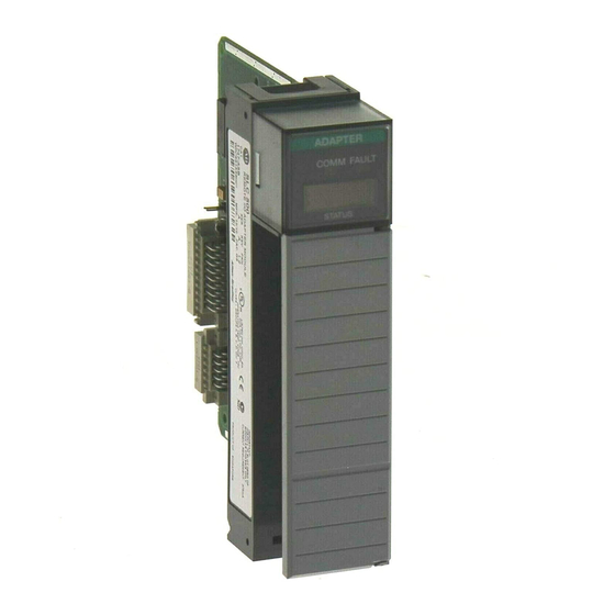
- Page 36 Quick Start for Experienced Users Check that the module is operating correctly. Reference During normal operation (PLC or SLC in Run mode), the 1747-ASB module appears as shown Chapter 6 (Start-Up and below: Operation) ADAPTER Chapter 7 (Troubleshooting) COMM F AULT Green COMM LED is on.
- Page 37 Quick Start for Experienced Users Publication 1747-UM006B-EN-P - June 2003 Artisan Technology Group - Quality Instrumentation ... Guaranteed | (888) 88-SOURCE | www.artisantg.com...
-
Page 38: Chassis Overview
• 2-slot, 1-slot, and 1/2-slot addressing • how I/O module images are mapped The 1747-ASB module controls 1 remote chassis and up to 2 remote expansion chassis with a maximum of 30 slots. Currently, there are four different types of chassis available. -
Page 39: Slot Numbering
The remote chassis and remote expansion chassis slots are numbered from 0 to 30. The 1747-ASB module must reside in slot 0. Slots numbered 31 and above cannot be used. -
Page 40: 2-Slot Addressing
Addressing Slot addressing refers to how each chassis slot is assigned a specific amount of the 1747-ASB module image. The amount depends on which type of slot addressing you choose; 2-slot, 1-slot, and 1/2-slot addressing is available, as shown below:... - Page 41 Addressing 2-Slot Addressing When the 1747-ASB module is configured for 2-slot addressing, the processor addresses two chassis slots as one logical group. Each slot, beginning with slot 1, is sequentially assigned one byte (8 bits) of the 1747-ASB module's input and output image. Each terminal on a discrete I/O module installed in a slot is assigned a bit within the byte, beginning with the least significant bit.
-
Page 42: 2-Slot Addressing Considerations
If block transfer mode is selected, all specialty I/O modules are block transfer mapped regardless of their image size. The 1747-ASB module can block transfer map a maximum of eight words. Publication 1747-UM006B-EN-P - June 2003... -
Page 43: 2-Slot Addressing Examples
Slot 18 Slot 18 Slot Pair 9 If images overlap, a 1747-ASB module error occurs. For example, if 16 point input modules are installed in slots 1 and 2, their input images overlap and a 1747-ASB module error occurs. Publication 1747-UM006B-EN-P - June 2003... -
Page 44: 1-Slot Addressing
I/O modules whose image size is less than or equal to one word but more than one byte. Slot 1 is assigned to the first logical group of the 1747-ASB Slot 1 module’s image, beginning with bit 0 (the LSB). -
Page 45: 1-Slot Addressing Considerations
1746-NI4, -NO4I, -NO4V, and -HS. If the block transfer mode is selected, all specialty I/O modules are block transfer mapped regardless of their image size. The 1747-ASB module can block transfer map a maximum of eight words. Publication 1747-UM006B-EN-P - June 2003... -
Page 46: 1-Slot Addressing Examples
Slot 18 Slot 18 = unused If images overlap, a 1747-ASB module error occurs. For example, if 32-point input modules are installed in slots 1 and 2, their input images overlap and a 1747-ASB module error occurs. Publication 1747-UM006B-EN-P - June 2003... -
Page 47: 1/2-Slot Addressing
Each slot, beginning with slot one, is sequentially assigned two words (32 bits) of the 1747-ASB module's input and output image. Each terminal on the I/O module is assigned a bit within the word, beginning with the least significant bit. -
Page 48: 1/2-Slot Addressing Considerations
1746-BAS. If the block transfer mode is selected, all specialty modules are block transfer mapped regardless of the image size. The 1747-ASB module can block transfer map a maximum of eight words. Publication 1747-UM006B-EN-P - June 2003... -
Page 49: 1/2-Slot Addressing Examples
Input modules must be paired with output modules so their input or output images, refer to the complementary I/O description, found on page 4–5. images do not overlap. 1747-ASB Input Image 1747-ASB Output Image 1747-ASB Input Image 1747-ASB Output Image... -
Page 50: How I/O Module Images Are Mapped
Addressing 3-13 How I/O Module Images The method of transferring an I/O module's image to the 1747-ASB module's image is referred to as image mapping, or mapping. An I/O Are Mapped image can be discretely mapped or block transfer mapped. How the module's image is mapped depends on the type of module you are using (discrete or specialty I/O). -
Page 51: How Specialty I/O Module Images Are Mapped
When block transfer mode is selected, all specialty modules that are block transfer mapped use one byte in the 1747-ASB module's input and output image. These bytes reside in the least significant byte of the 1747-ASB image reserved for the module's slot. -
Page 52: When Discrete Mode Is Selected
RIO block transfers for a logical device, at least four RIO scans are required to complete these RIO block transfers. The 1747-ASB module can block transfer up to a maximum of 8 words per block transfer. 1747-ASB module exchanges data with the speciality I/O module via the backplane. - Page 53 For example, if the specialty I/O module such as the 1746-NIO4I and -NIO4V requires two words of input and output image, and the 1747-ASB module is configured for 1-slot addressing, the specialty I/O module is discretely mapped . However, if four words of input or output image are required, the specialty I/O module such as the 1746-NI4, -NO4V, -NO4I, and -HS, are block transfer mapped.
- Page 54 5 to 8 Words 1-slot Block transfer -HSTP1 1747-DCM 1/2-slot Block transfer The 1747-ASB module can block transfer map a maximum of eight words. Publication 1747-UM006B-EN-P - June 2003 Artisan Technology Group - Quality Instrumentation ... Guaranteed | (888) 88-SOURCE | www.artisantg.com...
- Page 55 3-18 Addressing Publication 1747-UM006B-EN-P - June 2003 Artisan Technology Group - Quality Instrumentation ... Guaranteed | (888) 88-SOURCE | www.artisantg.com...
-
Page 56: Configuration
This chapter presents the configuration options made through the various DIP switch settings. DIP Switch Information The 1747-ASB module parameters are configured by three DIP switches, shown below. To assist you in the configuration of multiple 1747-ASB modules, a configuration worksheet is provided in Appendix C. -
Page 57: Dip Switch Sw1
Primary/Complementary Chassis When configured as a complementary chassis (SW2 switch 3), the Reserved 1747-ASB module can appear on the RIO link as any starting logical ASB Module Image Size rack between 0 and 62 (0 to 76 octal). When configured as a primary chassis (SW2 switch 3), the 1747-ASB... - Page 58 Configuration Logical Rack Number (Octal) Switch Number (SW1) 1747-SN PLC 2 PLC 3 PLC 5/15 PLC 5/25 PLC 5/40 PLC 5/60 PLC 5/250 OFF OFF ON ON ON OFF OFF ON OFF OFF ON ON ON OFF OFF ON OFF OFF ON ON ON OFF OFF ON...
-
Page 59: Logical Group Number (Sw1-7,8)
If an invalid starting logical group number is selected, an error occurs. DIP Switch SW2 Baud Rate (SW2-1,2) SW2 switches 1 and 2 determine the baud rate the 1747-ASB module operates at while communi cating across the RIO link. The default is 57.6K as shipped from the factory. -
Page 60: Primary/Complementary Chassis (Sw2-3)
Baud Rate DIP Switch Settings 57.6K 115.2K 230.4K Invalid If the invalid switch setting is selected, a 1747-ASB module error occurs. Primary/Complementary Chassis (SW2-3) SW2 switch 3 determines whether the 1747-ASB module appears to the scanner as a primary or complementary chassis. - Page 61 If you want to use complementary I/O, two 1747-ASB modules are required. One 1747-ASB module is configured as a primary chassis, the other as a complementary chassis. If a primary chassis exists, it is scanned first.
- Page 62 Complementary Chassis Logical Rack Number Logical Rack Number Decimal Octal (1) If a 1747-ASB module is configured as a primary chassis with a logical rack number greater than 7, a 1747-ASB module error occurs. If the logical rack numbers are not properly ATTENTION assigned, unpredictable operation of both 1747-ASB modules results.
- Page 63 Configuration I = Input Module = Output Module Slot Slot Slot Pair Slot Pair Complementary Chassis Primary Chassis Complementary Chassis Configured As: Primary Chassis Configured As: Logical Rack Number 8 (decimal) Logical Rack Number 0 Logical Group Number 0 Logical Group Number 0 Image Size (logical groups) 16 Image Size (logical groups) 16 Addressing Mode 1/2-slot...
-
Page 64: Reserved (Sw2-4)
I/O Module Keying ASB Module Image Size (SW2-5, 6, 7, 8) SW2 switches 5 through 8 determine the size of the 1747-ASB module's image that is reserved in the scanner. You must also make sure you do not exceed the maximum logical rack number, described on page 4-11. - Page 65 4-10 Configuration The 1747-ASB module image size can be between 2 and 32 logical groups, in 2 logical group increments. Logical Rack Number ASB Module Image Size DIP Switch Settings Logical Group Number Baud Rate Primary/Complementary Chass Reserved ASB Module Image Size...
- Page 66 Configuration 4-11 If after assigning your 1747-ASB module image size, IMPORTANT you exceed logical rack 62 in complementary mode (SW2 switch 3) or logical rack 7 in primary mode (SW2 switch 3), an error occurs. When assigning the starting logical rack and group numbers, make sure the size of...
- Page 67 4-12 Configuration The following examples illustrate how the selection of the 1747-ASB image size is determined by: • the addressing mode (2-slot, 1-slot, 1/2-slot) Logical Rack Number • the number of chassis slots required Logical Group Number 1747-ASB Module 1-Slot Addressing With Six Slots Available...
-
Page 68: Special Image And Chassis Size Considerations
Sometimes, logical slots and groups are not mapped due to chassis size and selected image size because: Size Considerations • There is not enough 1747-ASB module image to map all of the available slots. • The 1747-ASB image size exceeds requirements for available slots. -
Page 69: 1747-Asb Image Size Exceeds Slot Requirements
One Slot of Pair is Present, and 1747-ASB Module Image is Available for Both Slots When one slot of a pair is present and 1747-ASB module image is available for both slots, the single slot can use the extra image space. -
Page 70: 1747-Asb Module Image Space Available For One Slot
This condition only occurs in 1/2-slot addressing. When both slots of a pair are available but there is only enough 1747-ASB module image space available for one slot, the lower numbered slot uses the available image space. If a four word specialty module (i.e., 1746-NI4) is installed in this slot and the... - Page 71 SLC processor that is in the test mode. See the specialty I/O module's manual to determine the response to this condition. • The specialty I/O module's inputs are still read by the 1747-ASB module. However, the specialty I/O module's outputs are not modified by the 1747-ASB module.
-
Page 72: Processor Restart Lockout (Sw3-2)
RIO link communications are interrupted or if the 1747-ASB module is inhibited and re-enabled. While in the ON position, the 1747-ASB module does not respond if terminals 5 and 6 are shorted together. The 1747-ASB module is shipped from the factory with the default position ON (automatic restart). - Page 73 PLC auto configurations on the 1747-ASB module. If the 1747-ASB module has not received communications for all of its logical devices, you are able to perform PLC auto configurations once the 1747-ASB module is powered up. If processor restart lockout is not selected, you are able to perform PLC auto configurations on the 1747-ASB module.
-
Page 74: Addressing Mode (Sw3-5,6)
The 1747-ASB module is shipped from the factory with the default position ON (restricted). Last Chassis SW3 switch 4 is used for last chassis selection when the 1747-ASB module is connected to a PLC-2, PLC-5, or SLC scanner (Catalog Logical Rack Number Number 1747-SN).. - Page 75 Addressing Mode DIP Switch Settings 2-slot 1-slot 1/2-slot Invalid The 1747-ASB module is shipped from the factory with the default position selected for 1-slot addressing. Publication 1747-UM006B-EN-P - June 2003 Artisan Technology Group - Quality Instrumentation ... Guaranteed | (888) 88-SOURCE | www.artisantg.com...
-
Page 76: Specialty I/O Mode (Sw3-7)
Configuration 4-21 If the invalid switch setting is selected, a 1747-ASB module error occurs. 1/2-slot addressing is not supported by the PLC-2 family of processors. Specialty I/O Mode (SW3-7) SW3 switch 7 determines the specialty I/O mode (discrete or block transfer). -
Page 77: Switch Setting Summary
I/O Module Keying DIP Switch Settings Save Mode Check Mode The 1747-ASB module is shipped from the factory with the default position ON (save mode). Switch Setting Summary The following is a summary listing the various DIP switch settings. -
Page 78: Sw3
Configuration 4-23 • Hold Last State Hold Last State ON=Hold Last State Processor Restart Lockout OFF=Do Not HOld Last State Link Response (default) Last Chassis/PLC-3 Backup • Processor Restart Lockout Addressing Mode Bit 1 (MSB) ON=Automatic Restart (default) Addressing Mode Bit 0 (LSB) OFF=Processor Lockout Specialty I/O Mode •... - Page 79 4-24 Configuration Publication 1747-UM006B-EN-P - June 2003 Artisan Technology Group - Quality Instrumentation ... Guaranteed | (888) 88-SOURCE | www.artisantg.com...
-
Page 80: Installation And Wiring
1. Install the module in slot 0 of the remote chassis by aligning the circuit board with the chassis card guide. The 1747-ASB module must only be installed in slot 0 (the left slot) of the remote chassis. Do not install the 1747-ASB module in the remote expansion chassis. -
Page 81: Link Wiring
A daisy chain network is formed by connecting network devices together in a serial manner using Belden 9463 cable. Belden 9463 cable is the only approved cable for Allen-Bradley RIO links. Link Wiring The total number of adapters allowed on the RIO link are: •... -
Page 82: Correct Link Wiring
No two devices can be connected to the same point IMPORTANT on the link. An example of correct and incorrect link wiring is shown below. Correct Link Wiring 1747-ASB Module To Scanner 1747-ASB Module 1747-ASB Module Incorrect Link Wiring 1747-ASB Module... -
Page 83: Link Termination
1/2 Watt If the signal integrity on the RIO link is compromised IMPORTANT by environmental noise, improper termination, and/or improper cable installation, the 1747-ASB module scan rate drops. This is indicated by a pronounced flickering of the status display. To Scanner’s... -
Page 84: Wiring A Processor Restart Lockout Switch
Wiring a Processor Restart When processor restart lockout is enabled (SW3-2) and communications are restored, the 1747-ASB module does not respond Lockout Switch to any type of communications, or communication commands until terminals IN and RET are momentarily shorted together. This occurs while the RIO scanner is attempting to communicate with the 1747-ASB module. -
Page 85: I/O Module Addressing Labels
PLC processor on a logical rack, logical group basis and by the SLC processor on a 1747-SN scanner slot and word basis. A remote PLC and SLC label kit is included with each 1747-ASB module to assist you in addressing your I/O modules. -
Page 86: Octal Label Kit Installation
Installation and Wiring Octal Label Kit Installation The octal filter and door label must be used when working with a PLC processor as a master. An octal label kit is included with the I/O modules listed in the table on page 5-8. The kits can also be obtained through your Rockwell Automation distributor. -
Page 87: Octal Kit And I/O Module Information
Installation and Wiring Octal Kit and I/O Module Information Octal Kit Catalog Applies to I/O Number 1746- Module 1746- RL40 IA16 RL41 IB16 RL42 IG16 RL43 IM16 RL44 IN16 RL45 IV16 RL46 ITB16 RL47 ITV16 RL50 OA16 RL51 OB16 RL52 OG16 RL53 OV16... -
Page 88: Start-Up And Operation
1. Cycle the power one last time in save mode (SW3-8 ON). 2. Remove power from the system. 3. Remove the 1747-ASB module and set SW3-8 to the OFF position (check mode). 4. Replace the 1747-ASB module in slot 0. -
Page 89: Save Mode
After successfully completing a powerup and initialization sequence, the 1747-ASB module waits to receive RIO link communications from the scanner for all of its logical devices. Once the 1747-ASB module receives RIO link communication for all of its logical devices, it begins normal operation. -
Page 90: Normal Operation
Therefore, if one of the 1747-ASB module's logical devices is receiving reset adapter decide commands and another is inhibited, the 1747-ASB module treats all of its logical devices under its control as if they too were inhibited. Once the inhibit condition is cleared, the module treats all of its logical devices as if they were receiving reset adapter decide commands. -
Page 91: Inhibit Condition
• The enabled logical devices communicate on the RIO link. • The 1747-ASB module does not send output data to any of its output modules, even those that are enabled. • The 1747-ASB module does not process any RIO block transfer writes. - Page 92 Not read (1) This is the 1747-ASB module's operating mode, as compared to an SLC processor. For example, if the SLC state is TEST, the 1747-ASB module is controlling the specialty I/O modules in the same manner as an SLC processor would in the test mode. Refer to the appropriate SLC specialty I/O user's manual for more information.
-
Page 93: Remote Expansion Chassis Power Loss
The 1747-ASB module assigns each slot in the remote chassis and remote expansion chassis a fixed amount of its image using slot addressing. The 1747-ASB module then maps the I/O module's images to the portion of the 1747-ASB image that is assigned to their slots. Invalid RIO Link Transfers... -
Page 94: Rio Discrete Transfers To Block Transfer Chassis Slots
Start-Up and Operation RIO Discrete Transfers To Block Transfer Chassis Slots Discrete output image data received by the 1747-ASB module for a block transfer slot is ignored by the 1747-ASB module. Discrete input image data from the 1747-ASB module for block transfer slots may be non-zero. - Page 95 4. Configure the PLC or SLC processor so that the scanner will communicate on the RIO link with the 1747-ASB module. Place the processor in the test mode. The 1747-ASB module display appears as shown below: Green COMM LED is off.
-
Page 96: I/O Module Insertion Into A Slot
1747-ASB module image, is always scanned by the 1747-ASB module. (1) Loss of power to the remote chassis or remote expansion chassis is considered a 1747-ASB module error. I/O modules can be inserted or removed from a remote expansion chassis that is not powered, even if the remote chassis is powered. -
Page 97: I/O Module Removal From An Unscanned Slot
Any block transfer mapped specialty I/O module which is mapped into the 1747-ASB image having only output image, is scanned by the 1747-ASB module only when a block transfer write to the I/O module occurs. -
Page 98: Troubleshooting
This chapter presents status display information during operational and fault conditions. The 1747-ASB module has two LEDs and a status display. These LEDs and status display are used to indicate operating status and error conditions while the module is operating. -
Page 99: Contacting Rockwell Automation
HLS. (2) Some, but not all of the 1747-ASB module's logical devices are receiving RIO link communications from the scanner. The 1747-ASB module is returning valid input data to the scanner, but is not turning outputs on or off. -
Page 100: Error Codes For Error Conditions
Corrective Action Display Power Up Self Test in progress This appears for less than one second after power is applied. Replace the 1747-ASB module if condition persists. Powerup OK. 1747-ASB This occurs for several seconds configuring RIO image. after power is applied. Replace the 1747-ASB module if condition persists. - Page 101 1747-ASB module was powered Code 2 up in save mode (SW3-8) do not match the current settings now that the 1747-ASB module is in check mode. flashing I/O Configuration Mismatch and Correct the I/O module...
-
Page 102: Dip Switch Configuration Mismatch Fault Codes - Codes 1 And 2
(1) 8 indicates the 1747-ASB module has encountered an unrecoverable fault. (2) Slot # is a 2-digit decimal slot number between 1 and 31. 31 indicates the offending slot could not be detected. (3) The Status Display alternates between these two codes. Code 1 is the incorrect parameter, Code 2 is the expected (saved) parameter`s value. - Page 103 Troubleshooting Starting Logical Group mismatch. 1-digit decimal value previously saved is displayed (group 0, group 2, etc.). Baud Rate mismatch. Baud rate previously saved is displayed. Abbreviated values are used. Primary/Complementary Selection mismatch. The mode previously saved is displayed. Image Size mismatch. Number of groups from 02 to 32 decimal indicates previously saved selection.
-
Page 104: Fault Codes - Code 3
Troubleshooting Addressing Mode mismatch. 1/2-slot, 1-slot, and 2-slot indicates previously saved selection. Specialty I/O Mode mismatch. Discrete (dSc) or Block Transfer (bL) indicates previously saved selection. C stands for configuration, the first number from the left is the DIP switch number (SW1, SW2, or SW3). -
Page 105: I/O Runtime Fault Codes - Code 4
Troubleshooting I/O Runtime Fault Codes - Code 4 Meaning Code 4 I/O Parity Error Hardware Parity Error or module installed or removed under power I/O Module Removed Under Power File Access Grant Timeout (specialty I/O only) I/O Module Fault (generic) I/O Module Reported Error Code through I/O Module Reported Error Code Unknown... -
Page 106: Basic Slc 500 Example Using And Rio Scanner
A RIO scanner, Catalog Number 1747-SN, resides in slot 3 of the local chassis. The scanner controls one remote 7-slot chassis using one 1747-ASB module. The 1747-ASB module controls the following I/O modules: • 1746-IA16, 16-point 100/120 VAC input module in slots one, two, and three •... -
Page 107: Rio Device Configuration
Bulb 2 is connected to to output 1. to input 15. output 12. RIO Device Configuration The 1747-ASB module is configured in the following manner. Function 1747-ASB Module 1 Starting logical rack number Starting logical group number Image size (number of logical groups) -
Page 108: Slc Processor Image
SLC processor image is comprised of the local I/O module images and the RIO scanner images. The RIO scanner image size is four logical racks. The 1747-ASB module is in the RIO scanner image. SLC Processor Input Image SLC Processor Output Image... -
Page 109: 1747-Asb Module Configuration Details
Not Used I:3.7 O:3.7 The 1747-ASB module is configured as the last chassis because it uses the highest numbered logical group in the highest logical rack it resides in. The 1747-ASB module is configured for hold last state and processor restart lockout. -
Page 110: Rio Address Label Examples
SLC processor based on the slot location of the SN and the word that the I/O module uses in the SN image. A label kit is included with each 1747-ASB module to assist you in addressing I/O modules. - Page 111 Application Examples Shown below are examples of how the labels are filled out. The switch is connected Bulb 2 is connected The meter is connected Bulb 1 is connected to output 1. to input 15. to output 12. to output 4. 0 –...
-
Page 112: Application Example Program
The scanner controls two remote expansion chassis (one Using and RIO Scanner 7-slot and one 4-slot) and a RediPANEL. 1747-ASB module 1 controls the following I/O modules: • 1746-NIO4I, analog module (2 current/voltage inputs and 2 current outputs) • 1746-IV32, 32-point 24VDC sourcing input module •... - Page 113 Application Examples 1747-ASB module 2 controls the following I/O modules: • 1746-OA8, 8-point AC output module • 1746-IO12, 6-point input/output module • 1746-IA16, 16-point AC input module The application is illustrated below. When the switch is closed, bulbs 1 and 2 turn on and an analog signal is moved to analog module output 1, which leads to the meter.
-
Page 114: Rio Device Configuration
Application Examples RIO Device Configuration The 1747-ASB modules and RediPANEL are configured in the following manner. Function 1747-ASB 1747-ASB RediPANEL Module 1 Module 2 Starting logical rack number Starting logical group number Image size (number of logical groups) Addressing mode... -
Page 115: Slc Processor Image
O:3.31 1747-ASB Module 1 Configuration Details Because 1747-ASB module 1's image crosses the logical rack boundary of racks 1 and 2, 1747-ASB module 1 appears as two logical devices to the RIO scanner. SLC Processor Input Image SLC Processor Output Image... -
Page 116: 1747-Asb Module 2 Configuration Details
Application Examples 8-11 1747-ASB module 1 is not configured as the last chassis because the highest numbered logical group it uses (Group 3) is not the highest numbered logical group in the highest logical rack it resides in. The RediPANEL uses the highest numbered logical group (Group 7) in logical rack 2. -
Page 117: 1747-Asb Module 1 I/O Mapping Details
Application Examples 1747-ASB Module 1 I/O Mapping Details Because 1747-ASB module 1 is configured for 1-slot addressing, has six logical groups and six slots available for I/O, all of the slots present are mapped into the scanner image. No extra slots in the chassis, or extra words in the image remain. -
Page 118: Rio Address Label Examples
SLC processor based on the slot location of the SN and the word that the I/O module uses in the SN image. A label kit is included with each 1747-ASB module to assist you in addressing I/O modules. - Page 119 8-14 Application Examples Shown below are examples of how the labels are filled out. RediPANEL The meter is connected to output 1. The switch is connected to input 17. Bulb 2 is connected to output 12. Bulb 1 is connected to output 4. 0 –...
-
Page 120: Application Example Program
Application Examples 8-15 Application Example Program Shown below is an excerpt from the user program. When the switch is closed, bulbs 1 and 2 turn on and the decimal value 5555 is moved to analog output 1 and is converted to an analog signal. I:3.17 MOVE Source... -
Page 121: Plc-5 Example
Application Examples PLC-5 Example The PLC-5/40 built-in scanner controls two 1747-ASB modules. 1747-ASB module 1 controls a 7-slot and 10-slot chassis. The I/O modules residing in those chassis are: • 1746-NIO4V, analog module (2 current or voltage inputs and 2 voltage outputs) •... -
Page 122: Rio Device Configuration
This kit is also available as a replacement part through your Rockwell Automation distributor. RIO Device Configuration The 1747-ASB modules are configured in the following manner. Function 1747-ASB Module 1 1747-ASB Module 2 Starting logical rack number... -
Page 123: Plc Processor Image
I:017 Group 7 O:017 IG16 OG16 OG16 IG16 Group 0 Group 0 I:020 O:020 Group 1 I:021 Group 1 O:021 1747-ASB 1747-ASB OB16 IB16 IB16 OB16 Group 2 I:022 Group 2 O:022 Logical Logical NO4V Module 1 Module 1 NO4V... -
Page 124: 1747-Asb Module 1 Configuration Details
8-19 1747-ASB Module 1 Configuration Details Because the image of the 1747-ASB module 1 crosses logical rack boundary 1 and 2, 1747-ASB module 1 appears as two logical devices to the RIO scanner. PLC Processor Input Image PLC Processor Output Image... -
Page 125: 1747-Asb Module 2 Configuration Details
8-20 Application Examples 1747-ASB Module 2 Configuration Details Because the image of 1747-ASB module 2 does not cross a logical rack boundary, 1747-ASB module 2 appears as one logical device to the scanner. PLC Processor Input Image PLC Processor Output Image... -
Page 126: 1747-Asb Module 1 I/O Mapping Details
8-21 1747-ASB Module 1 I/O Mapping Details Because 1747-ASB module 1 is configured for 2-slot addressing, has eight logical groups and 16 I/O slots available, all of the slots present are mapped into the PLC-5/40 image. No extra slots in the chassis or extra words in the image remain. -
Page 127: 1747-Asb Module 2 I/O Mapping Details
1746-NIO4I module in slot three requires two input and output words, the 1746-NIO4I module can be installed in slot three. If a four word input or output module is installed in slot three, a 1747-ASB module error occurs because only half of the module's image can be mapped. -
Page 128: Rio Address Label Examples
I/O modules controlled by the 1747-ASB module are addressed by the PLC processor on a logical rack, logical group basis. A label kit is included with each 1747-ASB module to assist you in assigning the logical rack and logical group designation for each I/O module. -
Page 129: Application Example Program
8-24 Application Examples Application Example Program Shown below is an excerpt from the user program. When the switch is closed, the bulb illuminates, decimal value 5555 is moved to the 1746-NO4V output 2 (connected to meter 2) and to the 1746-NIO4I output 0 (connected to meter 1). - Page 130 Appendix Specifications This appendix provides adapter and system specifications, as well as throughput information. Topics include: • adapter operating specifications • network specifications • throughput introduction • calculating throughput Adapter Operating Specifications Backplane Current Consumption 375mA at 5V Operating Temperature 32°...
- Page 131 82Ω 1/2 Watt Throughput is the time between when a control system senses an input event on an I/O module in a 1747-ASB chassis to when an output event occurs on an I/O module within the same 1747-ASB chassis. There are three types of 1747-ASB module throughput: Troughput Production •...
- Page 132 1747-ASB module during a discrete scan. The 1747-ASB module writes the output data to a discretely mapped output module during a 1747-ASB module backplane scan. The output data exits the chassis via the I/O module in order to control the field device.
- Page 133 • There are no RIO block transfers occurring on the RIO link to any chassis. If RIO block transfers are present on the RIO link or if the 1747-ASB chassis has block transfer mapped I/O modules, you must use the Discrete I/O Throughput with Block Transfers Present section.
- Page 134 Specifications RIO Scan Time Calculation (T The RIO scan time is calculated by identifying the baud rate and image size of each logical device on the RIO link. Locate the corresponding time value in the following table. If you are using multiple logical devices, add the time values together to determine the total RIO scan time (T RIO)
- Page 135 115.2K baud 1.32T + 1.58 230.4K baud 1.67T + 2.00 (1) Only modules mapped to the 1747-ASB image; unmapped modules are not scanned. Publication 1747-UM006B-EN-P - June 2003 Artisan Technology Group - Quality Instrumentation ... Guaranteed | (888) 88-SOURCE | www.artisantg.com...
- Page 136 A PLC 5/40 is controlling an RIO link running at 115.2K baud that has the following adapters: • One 1747-ASB module configured as 1/2 logical rack with 1-slot addressing and discrete specialty I/O mode – slot 1 - 1746-IB16, 16-point input module –...
- Page 137 Specifications These values are listed in the Backplane Scan Time table on page A-6. 4. Add the backplane scan times together for each module in slots one, two, and three. ) = T base backplane scan time I/O module 1 I/O module 2 I/O module 3 = 0.325ms + 0.273ms + 0.625ms + 0.620ms...
- Page 138 The information in this section is used to calculate the discrete throughput of the 1747-ASB module if either of the following conditions are true: • There are block transfer mapped I/O modules in the 1747-ASB chassis. • There are RIO block transfers occurring on the RIO link to any chassis.
- Page 139 Discrete I/O Throughput with Block Transfers Present Example A PLC 5/40 is controlling a 115.2K baud RIO link that has 3 adapters and 4 logical devices. 1747-ASB module: • starting logical rack 0, logical group 0 • 12 logical groups (1 1/2 logical racks) •...
- Page 140 2. Determine the maximum length of the block transfer to each logical device. There are two logical devices for the 1747-ASB module. The largest block transfer that is possible with the full logical rack, logical device is 8 words. The largest block transfer that is possible with the 1/2 logical rack, logical device is 2 words.
- Page 141 (3) The time involved to block transfer data is calculated using the T formula in the previous section. (4) The 1747-ASB backplane scan time is calculated in the same manner as described in the discrete throughput sections. Publication 1747-UM006B-EN-P - June 2003...
- Page 142 Differences Between the 1747-ASB Module and the 1771-ASB Series C Module This appendix examines the differences between Catalog Number 1747-ASB and Catalog Number 1771-ASB Series C, Revision E or later. These differences are: • image size selection • hold last state operation •...
- Page 143 • the 1771-ASB module is inhibited • the 1771-ASB module receives reset, adapter decide commands from the scanner When the hold last state mode is selected the 1747-ASB module holds discrete outputs in their last state if: • RIO communications are lost •...
- Page 144 Differences Between the 1747-ASB Module and the 1771-ASB Series C Module Inserting and Removing I/O Modules Under Power Disconnect power to the 1771- or 1747-ASB ATTENTION chassis before attempting to insert, remove, or (page 6-9) wire any I/O modules. In most cases, inserting or removing I/O modules while under power does not cause a 1771-ASB error.
- Page 145 Differences Between the 1747-ASB Module and the 1771-ASB Series C Module If the 1747-ASB module is configured for the block transfer mode, it handles all specialty I/O modules in the same manner as the 1771-ASB module does by using RIO block transfers.
- Page 146 (page 6-3) • communicate on the RIO link • control outputs in its chassis If some, but not all, of the 1747-ASB logical devices are inhibited, the 1747-ASB module: • continues to communicate on the RIO link if processor restart...
- Page 147 Differences Between the 1747-ASB Module and the 1771-ASB Series C Module Publication 1747-UM006B-EN-P - June 2003 Artisan Technology Group - Quality Instrumentation ... Guaranteed | (888) 88-SOURCE | www.artisantg.com...
- Page 148 Use this worksheet to record the DIP switch settings for each of your module. DIP Switch Configuration Self Locking Tab DIP Switches 1747-ASB Module Hold Last State Baud Rate Bit 1 (MSB) Logical Rack Number Bit 5 (MSB) Processor Restart Lockout...
- Page 149 DIP Switch and Address Configuration Worksheets Hold Last State Baud Rate Bit 1 (MSB) Logical Rack Number Bit 5 (MSB) Processor Restart Lockout Baud Rate Bit 0 (LSB) Logical Rack Number Bit 4 Module _ Link Response Primary/Complementary SLC Chassis Logical Rack Number Bit 3 Last Chassis/PLC-3 Backup Reserved...
- Page 150 DIP Switch and Address Configuration Worksheets Address Configuration Use this worksheet to address the I/O modules residing in the 1747-ASB module chassis. SLC Processor Input Image SLC Processor Output Image High Byte Low Byte High Byte Low Byte Bit Number...
- Page 151 DIP Switch and Address Configuration Worksheets SLC Processor Input Image SLC Processor Output Image High Byte Low Byte High Byte Low Byte Bit Number Decimal Bit Number Decimal Group 0 Group 0 I:e.0 O:e.0 Group 1 Group 1 O:e.1 I:e.1 Group 2 Group 2 O:e.2...
- Page 152 SLC example 8-3, 8-4 transferring data 1-7 in PLC example 8-17, 8-18, 8-21, 8-22 block transfer mode 3-14 in SLC example 8-9, 8-12, 8-13 Allen-Bradley 7-2 contacting for assistance 7-2 application example program 8-7 cable distances 5-2 maximum 5-2...
- Page 153 SLC application 8-7 extended node capability 1-8 definitions 1-3 link termination 5-4 of scanners and adapters 1-8 differences between 1747-ASB and of the ASB module 1-8 1771-ASB series c modules B-1 DIP switch locations B-4 hold last state B-2 I/O module keying B-4...
- Page 154 Index inhibit 6-4 status display codes for normal operating conditions 7-2 installing the ASB module in an SLC chassis 5-1 invalid RIO link transfers 6-6 PLC application example 8-15 application example program 8-24 ASB module 1 configuration 8-19 labels, addressing ASB module 1 I/O mapping 8-21 attaching to the I/O modules 2-5, 5-6 ASB module 2 configuration 8-20...
- Page 155 1-7 in SLC example 8-9, 8-12, 8-13 RIO discrete example 1-7 specialty I/O modules 3-14 troubleshooting 7-1 mapping 3-14 contacting Allen-Bradley 7-2 block transfer mode 3-15 major error 7-1 discrete mode 3-16 minor error 7-1 overview 3-13 specifications A-1...
- Page 156 Artisan Technology Group - Quality Instrumentation ... Guaranteed | (888) 88-SOURCE | www.artisantg.com...
- Page 157 Publication 1747-UM006B-EN-P - June 2003 Supersedes Publication 1747-6.13 - December 1996 Copyright © 2003 Rockwell Automation. All rights reserved. Printed in the U.S.A. Artisan Technology Group - Quality Instrumentation ... Guaranteed | (888) 88-SOURCE | www.artisantg.com...
- Page 158 Artisan Technology Group is your source for quality new and certified-used/pre-owned equipment SERVICE CENTER REPAIRS WE BUY USED EQUIPMENT • FAST SHIPPING AND DELIVERY Experienced engineers and technicians on staff Sell your excess, underutilized, and idle used equipment at our full-service, in-house repair center We also offer credit for buy-backs and trade-ins •...