Table of Contents

Related Manuals for Allen-Bradley Guardmaster GuardLink


Summary of Contents for Allen-Bradley Guardmaster GuardLink
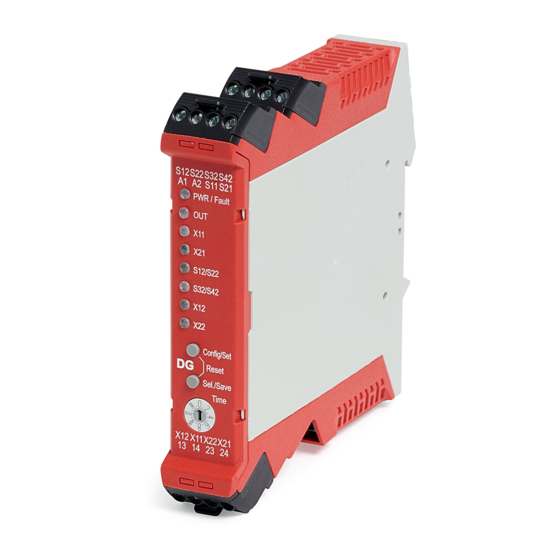
- Page 1 User Manual Original Instructions Guardmaster GuardLink Safety System Catalog Numbers 440R-DG2R2T (DG Safety Relay); 440S-SF8D, 440S-SF5D, 440S-MF5D, 440S-MF8D (Taps); 898D-418U-DM2 (Terminator); 440S-GLTAPBRKx (Bracket); 440R-ENETR (EtherNet/IP Network Interface)
- Page 2 Important User Information Read this document and the documents listed in the additional resources section about installation, configuration, and operation of this equipment before you install, configure, operate, or maintain this product. Users are required to familiarize themselves with installation and wiring instructions in addition to requirements of all applicable codes, laws, and standards.
-
Page 3: Table Of Contents
Table of Contents Preface Who Should Use This Manual ........7 Summary of Changes . - Page 4 Table of Contents Chapter 4 Power, Ground, and Wire Wiring Requirements and Recommendation ....37 DG Safety Relay..........37 Wire Size .
- Page 5 Table of Contents Chapter 9 440R-ENETR Network Interface Add-on Profile (AOP) ......... 61 Add a 440R-ENETR Interface to the Project .
- Page 6 Table of Contents Appendix C Regulatory Approvals Agency Certifications......... 117 Waste Electrical and Electronic Equipment (WEEE).
-
Page 7: Preface
Preface This user manual is a reference guide for the GuardLink™ safety system, plug-in modules, and accessories. It describes the procedures that you use to install, wire, and troubleshoot your relay. This manual explains how to install and wire your relay and gives you an overview of the GuardLink safety system Who Should Use This Manual Use this manual if you are responsible for the design, installation, programming, or troubleshooting of control systems that use the GuardLink... - Page 8 Preface • GuardLink Safety Signal - A known dynamic safety signal in operational mode and a two-way communication signal that the DG safety relay initiates to determine the status of the taps in the safe state. • HI - The ON state of the output of a logic block or the state of an input to a logic block or a voltage level to be above the turn-on threshold.
-
Page 9: Additional Resources
A glossary of industrial automation terms and abbreviations. You can view or download publications at http://www.rockwellautomation.com/global/literature-library/overview.page. To order paper copies of technical documentation, contact your local Allen-Bradley distributor or Rockwell Automation sales representative. Rockwell Automation Publication 440R-UM015C-EN-P - April 2018... - Page 10 Preface Notes: Rockwell Automation Publication 440R-UM015C-EN-P - April 2018...
-
Page 11: Overview
Chapter Overview What Is a GuardLink System? A GuardLink system is a collection of components to simplify a series connection of safety devices while achieving the highest industrial safety rating. The system has these important features: • Simplifies the connection of series connected safety devices. •... -
Page 12: Taps
Chapter 1 Overview Figure 1 - Typical GuardLink System Each DG safety relay can accommodate up to two GuardLink circuits, each containing up to 32 devices. One DG safety relay One GuardLink tap for each safety device. One terminator for each GuardLink circuit. -
Page 13: Dg Safety Relay
Overview Chapter 1 DG Safety Relay The DG safety relay is the host of the GuardLink system. By using a sequence of push buttons on the front face, the DG safety relay can be configured for many types of safety applications. The DG safety relay can do the following: •... -
Page 14: Reset
Chapter 1 Overview Reset The DG safety relay reset function can be applied one of three ways: • Automatic reset (no connection needed) • Monitored manual reset by a momentary push button that is connected to an input terminal • With an Ethernet interface, the machine control system can initiate the reset function. -
Page 15: Guardlink Principle Of Operation
Overview Chapter 1 Figure 3 shows an example of a DG safety relay operating as the equivalent of a DI safety relay. In Figure 3, the DG safety relay is configured to accept two input devices, control and monitor two contactors with a manual reset input. The 440R-ENETR interface reports the status to the machine control system. - Page 16 Chapter 1 Overview Initialization State The initialization state starts when power is applied to the GuardLink circuit and ends when the GuardLink circuit enters the safe state. If no errors exist, the GuardLink circuit transitions to the safe state; the initialization state cannot transition to the operational state.
-
Page 17: Guardlink Transition From Safe State To Operational State
Overview Chapter 1 Fault State The DG safety relay and the taps have two fault states: recoverable and non-recoverable. When a fault occurs, the taps and DG safety relay are in a safe state. Diagnostic information is provided by the indicators. The DG safety relay also sends diagnostic information to the EtherNet/IP interface. -
Page 18: Ossd Tap
Chapter 1 Overview OSSD Tap The OSSD tap is designed to specifically interface with safety products that generate OSSD outputs. The OSSD tap does not perform testing on the OSSD signals as the input device must perform the test. The OSSD tap is looking to see if the outputs of the connected device are energized or de-energized. -
Page 19: Guard Locking Application Example
Overview Chapter 1 When multiple guard locking devices are installed on a GuardLink system, the DG safety relay inserts a short delay between commands to each successive device to minimize the momentary inrush current to the solenoids. The device closest to the DG safety relay receives the command first. The device furthest away from the DG safety relay receives the command last. - Page 20 Chapter 1 Overview The SensaGuard switches allow immediate access to the machine. Additional risk reduction measures must be provided to prevent access to the hazards during the timing period. Because guard locking is used, a 440R-ENETR interface must be included in the application.
- Page 21 Overview Chapter 1 • Circuit Status The gates monitored by the SensaGuard interlock switches are closed. The guard locking switches are closed and locked. The DG and EM safety relays are OFF and ready for reset. • Starting Press the Reset button to energize the DG and EM safety relays. Their output contacts close.
- Page 22 Chapter 1 Overview Notes: Rockwell Automation Publication 440R-UM015C-EN-P - April 2018...
-
Page 23: Guardlink System Design
Chapter GuardLink System Design The design of a GuardLink circuit requires knowledge of the power requirements of the input devices and the length of the link cables. A voltage drop occurs across each tap. The cumulative voltage drop determines the number of taps that can be included in the circuit. -
Page 24: System Current Calculation
Chapter 2 GuardLink System Design Figure 6 - Tap Connections Safety Device 2 Safety Device 1 Safety Device 3 Device Cable Device Cable Device Cable INPUT INPUT INPUT Fuse Link Cable Link Cable Link Cable SLO-BLO™ Terminator V J1 V J2 V J3 + + - - Vs=24V Power... -
Page 25: Voltage Drop Consideration
GuardLink System Design Chapter 2 Voltage Drop Consideration With the potential of using up to 32 taps and long cable lengths between taps, the voltage available to the safety devices at connector J3 must be calculated. The voltage available to the safety device has two components: •... - Page 26 Chapter 2 GuardLink System Design The operating voltage specification of the tap is 20.4…26.4V. In the example that is shown in Table 4, the voltage at J1 of tap 6 has fallen below the lowest supply voltage specification of 20.4V DC. This system is not feasible, and remedial action must be taken (see Table IMPORTANT...
- Page 27 GuardLink System Design Chapter 2 To remedy the example in Table 4, the supply voltage can be increased from 24V to 26V as shown in Table 5. Now, all 13 taps meet the minimum voltage specification of 20.4V at connector J1. IMPORTANT Table 5 assumes the following:...
-
Page 28: Tap Cabling
Chapter 2 GuardLink System Design Tap Cabling The GuardLink system was designed with the intent of minimizing wiring by using quick-disconnect patchcords, while also allowing some manual wiring to terminals, when pinout incompatibilities exist. Figure 7 shows the recommended cable options for the various stages of a GuardLink system (to show the cable options only two taps are required, a full system has 32 taps). -
Page 29: Terminator
GuardLink System Design Chapter 2 Terminator The terminator (Figure 8), must be installed on the last tap to complete the link connection. The terminator contains internal electrical components specifically for a GuardLink system; other terminators cannot be used as substitutes. Figure 8 - Terminator —... - Page 30 Chapter 2 GuardLink System Design The safety system response time for the system that is shown in Figure 9 listed in Table 6. The time from when the SensaGuard interlock opens to the time when the 100S contactors drop out is 169.105 ms. The time from when the SensaGuard interlock opens to the time when the SWS signal turns OFF is 114.105 ms.
-
Page 31: Installation
Chapter Installation The DG safety relay uses the same housing as GSR modules. The module dimensions are shown in Figure 10, while Figure 11 shows the tap dimensions. Mounting Dimensions Figure 10 - DG Safety Relay Dimensions [mm (in.)] 22.5 113.6 (4.47) (0.88) S12 S22 S32 S42... -
Page 32: Din Rail Mounting And Removal
Chapter 3 Installation DIN Rail Mounting and The DG safety relay easily mounts onto 35 mm (1.4 in.) DIN rails: 35 x 7.5 x 1 mm (1.4 x 0.3 x 0.04 in.) (EN 50022 - 35x7.5). Removal 1. Hold the top at an angle (Figure 12). -
Page 33: Terminal Block Removal And Replacement
Installation Chapter 3 Terminal Block Removal and Terminal blocks can be removed and replaced following these instructions. Replacement Terminal Block Removal DG safety relays have removable terminal blocks. Use a screwdriver as a lever to remove the blocks. As shown in Figure 13, insert the screwdriver into the slot and pry up. -
Page 34: Tap Installation
Chapter 3 Installation Tap Installation The tap can be installed directly with two M5 screws. In Figure 15, the 38.5 mm (1.5 in.) wide tap fits neatly on a standard 40 mm (1.6 in.) aluminum extrusion construction profile. Figure 15 - Mounting Directly on 40 mm (1.6 in.) Profile INPUT 40 mm (1.6 in.) -
Page 35: Enclosure Considerations
Installation Chapter 3 Figure 18 shows some of the mounting options with the quick release bracket. The bracket can be mounted on various sizes of profile and can mount in-line or across the profile. Figure 18 - Mounting Options with Quick-release Bracket In-line with Profile Across Profile 20 mm Profile... -
Page 36: Prevent Excessive Heat
Chapter 3 Installation Prevent Excessive Heat Consider the following to help prevent excessive heat for your DG safety relay and tap. DG Safety Relay For most applications, normal convective cooling keeps the DG safety relay within the specified operating range. Verify that the specified temperature range is maintained. -
Page 37: Wiring Requirements And Recommendation
Chapter Power, Ground, and Wire Wiring Requirements and WARNING: Before you install and wire any device, disconnect power to Recommendation the system. WARNING: Calculate the maximum possible current in each power and common wire. Observe all electrical codes that dictate the maximum current allowable for each wire size. -
Page 38: Terminal Assignment And Function
Chapter 4 Power, Ground, and Wire Terminal Assignment and Function The relays have four terminals: two on the top and two on the bottom. As shown in Figure 19, the X2 and X4 terminal markings apply to the terminals further back. The X1 and X3 terminals apply to the terminals closest to the front. -
Page 39: Tap Pin Assignment And Function
The link connections carry the power and command signals. Figure 21 shows the functions of each pin. When using Allen-Bradley® Guardmaster patchcords and safety devices, you do not need to be concerned about the pin assignments, the system is connect and go. - Page 40 Chapter 4 Power, Ground, and Wire Figure 23 - J3 8-Pin EMSS (Female) Connector 2: Lock/Unlock Command 3: Aux Contact 8: Safety Contact A 1: Aux Contact 4: Safety Contact B 7: 0V 5: Safety Contact A 6: Safety Contact B Function Auxiliary (non-safety) contact Lock/Unlock command...
-
Page 41: Power Supply Connection
Power, Ground, and Wire Chapter 4 Bulletin 871A field-attachable quick-disconnect connectors can be used as shorting plugs during installation, troubleshooting, and for long distances. When the distance between taps exceeds 30 m (98.4 ft), a tap must be inserted into the GuardLink system at least every 30 m (98.4 ft). A shorting plug must then be added to the J3 connector. -
Page 42: Taps
Chapter 4 Power, Ground, and Wire Taps To comply with the CE (European) Low Voltage Directive (LVD), a DC source compliant with a protected extra low voltage (PELV) or, in certain circumstances, a safety extra low voltage (SELV) per IEC 60204-1 must power the tap. -
Page 43: Multiple Power Supplies
Power, Ground, and Wire Chapter 4 Multiple Power Supplies When separate power supplies are used for the DG safety relay and the GuardLink circuit, the protective earth connections must be at the same point. Figure 29 shows an example wiring diagram (catalog number 1606-XLE240EN is not Class 2 compliant;... -
Page 44: Devices With Ossd Outputs
Chapter 4 Power, Ground, and Wire Devices with OSSD Outputs Devices with OSSD outputs perform their own short circuit detection. The DG can be configured to accept up to two devices with OSSD signals. Connections of the OSSD outputs are shown in Figure Figure 31 - Wiring to Devices with OSSD Outputs +24V DC... -
Page 45: Single Wire Safety
Power, Ground, and Wire Chapter 4 Single Wire Safety The DG safety relay has the Single Wire Safety capability to expand the safety function (both input and output). SWS Connections The Single Wire Safety (SWS) feature allows a safety relay to expand the safety function to additional safety relays using one wire, provided all safety relays have the same voltage supply reference. -
Page 46: Safety Output Wiring
Chapter 4 Power, Ground, and Wire Figure 34 shows the characteristics of SWS signal when it is active. It starts with a 1 ms pulse, followed 700 µs later by a 500 µs wide pulse. This waveform is repeated every 4 ms. The tolerance of all edges is ±10%. When inactive, the SWS signal is 0V. -
Page 47: Surge Protection
Power, Ground, and Wire Chapter 4 Surge Protection Due to potentially high-current surges that occur when switching inductive load devices, such as motor starters and solenoids, the use of some type of surge suppression to help protect and extend the operating life of the relays is recommended. - Page 48 Chapter 4 Power, Ground, and Wire Notes: Rockwell Automation Publication 440R-UM015C-EN-P - April 2018...
-
Page 49: Config/Set Push Button
Chapter Configuration The DG safety relay has two push buttons on the front faceplate. These buttons are labeled Config/Set and Sel./Save. These push buttons allow you to do the following: • Configure the DG safety relay to perform a safety function •... -
Page 50: Configuration Mode
Chapter 5 Configuration Configuration Mode When you are in the configuration mode, the duration that the Config/Set button is depressed determines what the DG safety relay reveals. Button Press Function Short You can cycle through the configuration and can switch between the function of the blinking indicator. - Page 51 Configuration Chapter 5 Table 8 - Configuration Status Indicator Function Indicator Color and Setting Indicator Color and Setting Indicator Color and Setting Activate two Safety Functions Activate one Safety Function Number of Safety Functions — (IN1 and IN2) (only IN1) Activate GuardLink Input Activate OSSD or EMSS Input IN 1...
- Page 52 Chapter 5 Configuration 4. Short press the Config/Set button to change the function on the IN 2 status indicator, if available. Short press the Sel./Save button to accept and go to the next step. 5. Short press the Config/Set button to change the function on the OUT X status indicator.
-
Page 53: Delay Setting
Configuration Chapter 5 Delay Setting The delay is set by the 16 position switch as described in Table 9. The DG inputs must be opened during the delay. If the inputs close before the expiration of the delay time, the delayed output remains ON and any locked guards remain locked. -
Page 54: Push Buttons On The Front Of Dg Safety Relay
Chapter 5 Configuration Push Buttons on the Front of DG Safety Relay While in the Run mode, short presses of the Config/Set button can verify the configuration. IMPORTANT The PWR/Fault indicator remains green through these steps. 1. Short press the Config/Set push button. The indicators show the configuration. -
Page 55: Dg Safety Relay Status Indicators
Chapter Status Indicators DG Safety Relay Status Table 11 describes the status of the DG safety relay status indicators during normal operation. Indicators Table 11 - DG Indicators during Normal Operation Indicator State Description No power Solid Red DG safety relay is in self-test state or idle state PWR/Fault Solid Green Normal operation (Run mode) -
Page 56: Tap Status Indicators
Chapter 6 Status Indicators Tap Status Indicators Figure 37 shows the location of the two tap indicators: one for the input device connection and one for the link connection. Table 12 provides a description of the status for each indicator. Figure 37 - Tap Indicators Input indicator INPUT... -
Page 57: Pulse Testing For Inputs
Chapter Pulse Testing Functions Your DG safety relay uses pulse testing of inputs with voltage free contacts to detect short circuit conditions. The test pulses are used to detect three short circuit conditions: • Between the input terminals and +24V •... -
Page 58: Emss Smarttap Pulse Tests
Chapter 7 Pulse Testing Functions EMSS SmartTap Pulse Tests The EMSS SmartTap generates pulse tests to detect short circuit conditions. The waveforms are shown in Figure 40. The pulses are 1 ms wide. Channel 2 pulse occurs 8 ms after Channel 1. The pulses are repeated every 21 ms. When either of the input channels goes to an open state, the pulses are turned off. -
Page 59: Optical Bus
Chapter Opto-link Communications Optical Bus The GSR family of relays use an optical bus to communicate status information to the 440R-ENETR Guardmaster Ethernet/IP network interface . DG safety relays have two optical buses: • Bus 2 allows communication to pass from the 440R-ENETR interface to the DI, DIS, EM, EMD. -
Page 60: Arrangement With 440R-Enetr Interface
Chapter 8 Opto-link Communications Arrangement with Each 440R-ENETR interface can communicate with up to six GSR relays, in any combination. All DG safety relays must be located closest to the 440R-ENETR Interface 440R-ENETR interface, as shown in Figure Figure 42 - 440R-ENETR Interface Arrangement A1 A2 S12 S22 S32 S42 S12 S22 S32 S42... -
Page 61: Add-On Profile (Aop)
Chapter 440R-ENETR Network Interface Add-on Profile Status and control signal can be sent from the DG safety relay to the machine control system over EtherNet/IP by using the 440R-ENETR network interface. Add-on Profile (AOP) To use the 440R-ENETR network interface in a Logix Designer project, you must download and install the AOP. - Page 62 Chapter 9 440R-ENETR Network Interface Add-on Profile The Select Module Type window appears (Figure 44). 3. Find the 440R-ENETR. You can search, filter, or scroll to find it. 4. Click Create to add the module to the project. Figure 44 - Select Module Type The New Module window opens that shows the General information (Figure 45).
-
Page 63: Add Relays To The 440R-Enetr Interface
440R-ENETR Network Interface Add-on Profile Chapter 9 Add Relays to the There are two ways to add relays to the Ethernet module. 440R-ENETR Interface • Upload relays This preferred method requires the physical system to be complete, including relays, taps, and communications with the Ethernet Module. •... - Page 64 Chapter 9 440R-ENETR Network Interface Add-on Profile 5. Expand the AB_ETHIP-1 path. 6. Select the 440R-ENETR. 7. Click OK. 8. After the upload is completed, click OK. 9. Confirm the changes, click Yes. 10. Click OK to close the Module Definition window. Rockwell Automation Publication 440R-UM015C-EN-P - April 2018...
-
Page 65: Manual Method
440R-ENETR Network Interface Add-on Profile Chapter 9 11. Go on-line 12. Download the configuration to the controller. Manual Method Figure 46 shows the module definition and the steps necessary to add relays that the 440R-ENETR interface monitors. 1. Right-click Relay Bus. 2. - Page 66 Chapter 9 440R-ENETR Network Interface Add-on Profile Figure 47, the DG safety relay has been added to Slot 1 (the relay next to the 440R-ENETR interface). Each DG safety relay can have up to two GuardLink connections. By default, both GuardLink connections are disabled.
-
Page 67: Change The Order Of The Devices
440R-ENETR Network Interface Add-on Profile Chapter 9 Repeat the steps 4…6 to add as many modules that exist in the GuardLink chain. Remember that the order of the types of modules must be the same as the physical taps. Repeat the process for the second GuardLink chain, if a second GuardLink chain is used. - Page 68 Chapter 9 440R-ENETR Network Interface Add-on Profile When the nodes are established, click the OK button and confirm the module change by clicking Yes as shown in Figure Figure 52 - Confirm Module Change You return to the General tab. Use the Change button to add up to six relays.
-
Page 69: Controller Tags
440R-ENETR Network Interface Add-on Profile Chapter 9 Controller Tags When the Ethernet interface is added to the project, the tags that are shown in Figure 54 appear in the Controller Tags section of the Studio 5000 project. The Ethernet interface has both Input and Output tags. Notice the three relays match the example from Figure See publication... - Page 70 Chapter 9 440R-ENETR Network Interface Add-on Profile Table 13 - DG Safety Relay Tags Name Data Type Definition SafetyInput01 BOOL Safety Input 1 Status - Indicates whether safety input circuit 1 is On or Off. 0 = The input channel is Off. 1 = The input channel is On.
- Page 71 440R-ENETR Network Interface Add-on Profile Chapter 9 Table 14 shows the tags for GuardLink1. These tags apply to input IN1, which is wiring terminals S12 and S22. GuardLink2 has the same tags, but the tags apply to input IN2, which is wiring terminals S32 and S42. Table 14 - GuardLink 1 Tags Name Data Type...
- Page 72 Chapter 9 440R-ENETR Network Interface Add-on Profile Table 15 shows the 440R-ENETR interface input tags. These tags are read only and provide status of the communications to the Ethernet interface. Table 15 - 440R-ENETR Interface Input Tags Name Data Type Definition ConnectionFaulted BOOL...
- Page 73 440R-ENETR Network Interface Add-on Profile Chapter 9 The Ethernet interface can send commands to each of the relays that are included in the opto-links. Table 16 lists the tags for Relay 1, where Relay 1 is a DG safety relay. Output tags for other GSR relays can be found in publication 440R-UM009.
- Page 74 Chapter 9 440R-ENETR Network Interface Add-on Profile Table 17 - DG Safety Relay Fault Codes Fault Codes Type Name Description 0x0107 Recoverable GuardLink-CH[0] Tap 7 communication error No, or corrupted, communication 0x0108 Recoverable GuardLink-CH[0] Tap 8 communication error No, or corrupted, communication 0x0109 Recoverable GuardLink-CH[0] Tap 9 communication error...
- Page 75 440R-ENETR Network Interface Add-on Profile Chapter 9 Table 17 - DG Safety Relay Fault Codes Fault Codes Type Name Description 0x0114 Recoverable GuardLink-CH[1] Tap 20 communication error No, or corrupted, communication 0x0115 Recoverable GuardLink-CH[1] Tap 21 communication error No, or corrupted, communication 0x0116 Recoverable GuardLink-CH[1] Tap 22 communication error...
- Page 76 Chapter 9 440R-ENETR Network Interface Add-on Profile Table 18 lists the fault codes for the taps. Table 18 - Tap Fault Codes Fault Code Decimal (Hex) Name Description Recommended Action 00 (00) No fault — — 01 (01) Channel A fault Short circuit is detected on Channel A of the Check wiring monitored field device...
-
Page 77: I/O Faulted
440R-ENETR Network Interface Add-on Profile Chapter 9 I/O Faulted The following figures show how to remedy the I/O Faulted status on the EtherNet/IP interface. An exclamation mark in a small yellow triangle indicates a fault on the EtherNet/IP interface in the Controller Organizer panel. Figure 56 - I/O Faulted Identified With an EtherNet/IP connection, do the following: 1. - Page 78 Chapter 9 440R-ENETR Network Interface Add-on Profile 3. Click Upload to upload the configuration that is in the EtherNet/IP interface into the project. Figure 58 - Upload Next, you must select the upload path. 4. Expand your Ethernet connection. 5. Select your Ethernet interface. 6.
- Page 79 440R-ENETR Network Interface Add-on Profile Chapter 9 7. Click OK when upload is complete. Figure 60 - Upload Complete 8. Click Yes to confirm the change. 9. Click OK. Figure 61 - Confirm Change to Module Definition Rockwell Automation Publication 440R-UM015C-EN-P - April 2018...
-
Page 80: Studio 5000 Code Examples
Chapter 9 440R-ENETR Network Interface Add-on Profile 10. Go online to Run mode. 11. Download the new configuration to the controller. Figure 62 - Run and Download The process is complete. The EtherNet/IP interface no longer shows an I/O Fault. Studio 5000 Code Examples The following are examples of code that you encounter in the Studio 5000 environment. -
Page 81: Guardlink Fault Reset Commands
440R-ENETR Network Interface Add-on Profile Chapter 9 Figure 63 - Lock and Unlock Commands GuardLink Fault Reset Commands Figure 64 shows sample code to reset devices on the GuardLink circuit. Rung 16 uses an HMI input to reset all devices in the GuardLink circuit. First, we move a zero into the FaultResetCmd to clear out any previous commands. - Page 82 Chapter 9 440R-ENETR Network Interface Add-on Profile Notes: Rockwell Automation Publication 440R-UM015C-EN-P - April 2018...
-
Page 83: Guardlink System
Chapter Safety Function Calculations GuardLink System The GuardLink system typically consists of multiple taps and input devices. When calculating the Performance Level or the safety integrity level, the safety function must only consider the input device, the associated tap, the DG and EM safety relays, and the output devices driven by the safety relays. - Page 84 Chapter 10 Safety Function Calculations This system has eight safety functions; two functions for each input device. One function is for the DG outputs, and the second is for the expansion module outputs. The safety Function Block Diagrams are shown in Figure Figure 66 - Safety Function Block Diagrams Input...
-
Page 85: Sistema
Safety Function Calculations Chapter 10 SISTEMA SISTEMA is a free program that is used to determine the safety function values per ISO 13849. Many devices are preloaded into a Rockwell Automation library. The DG relay and taps were loaded into a local library, based on the safety data in Appendix C. - Page 86 Chapter 10 Safety Function Calculations Figure 68 shows a summary of the project. Each safety function has a required Performance Level of “e”, and each safety function has achieved that level. Figure 68 - Project Summary Rockwell Automation Publication 440R-UM015C-EN-P - April 2018...
-
Page 87: Dg Safety Relay
Appendix Specifications DG Safety Relay Table 20 - General Specifications — DG Safety Relay Attribute 440R-DG2R2T Dimensions, H x W x D 119.14 x 22.5 x 113.6 mm (6.49 x 0.88 x 4.47 in.) Shipping weight, approx. 225 g (0.5 lb) Wire size 0.2…2.5 mm ²... - Page 88 Appendix A Specifications Table 22 - Pulse Test Output Specifications — DG Safety Relay Attribute 440R-DG2R2T Wiring terminals S11/S21 Continuous output current, max 100 mA Surge output current, max 0.7 A Surge output current duration, max 5 ms Residual voltage drop from P/S, max 0.6V Load capacitance, max [nF/mA load] 200/20...
- Page 89 Specifications Appendix A Table 24 - SWS Specifications — DG Safety Relay Attribute 440R-DG2R2T Wiring terminal Output - X2 Input - X1 Continuous output current, max 50 mA ON state voltage drop (P/S to +), max 0.2V Surge output current, max 700 mA Surge output current duration, max 5 ms...
-
Page 90: Tap
Appendix A Specifications Table 26 - General Specifications — Tap Attribute 440S-SF8D, 440S-SF5D, 440S-MF5D, 440S-MF8D Dimensions, L x W x H 79.64 x 38.5 x 17 mm (3.14 x 1.51 x 0.67 in.) Shipping weight, approx. 27.2 g (0.96 oz) Case material Red RAL 3020 unfilled ABS MG47C plastic Mounting screw torque... - Page 91 Specifications Appendix A Table 28 - Environmental Specifications — Tap and Terminator Attribute Tap: 440S-SF8D, 440S-SF5D, 440S-MF5D, 440S-MF8D Terminator: 898D-418U-DM2 Temperature Operating -25…+70 °C (-13…+158 °F) Storage -40…+85 °C (-40…+185 °F) Relative humidity 35…85%, not exceed 50%RH at 70 °C (158 °F) Vibration per IEC 60068-2-6 10…55 Hz, 1 mm Shock per IEC 60068-2-27...
- Page 92 Appendix A Specifications Notes: Rockwell Automation Publication 440R-UM015C-EN-P - April 2018...
- Page 93 Appendix Configuration Examples This appendix contains examples of configurations. Each example contains the following: • Schematic This diagram shows the major connections. The input devices are not shown because of multiple configuration options. • Logic diagram This diagram shows the safety monitoring function (SMF), the logic level, and the safety output function (SOF).
-
Page 94: Configuration 10
Appendix B Configuration Examples Configuration 1 In Configuration 1, both safety inputs, Input 1 and Input 2, are in use. They can either be configured for GuardLink or OSSD with autodetect of EMSS devices. Input devices are not shown in the drawing. The input IN X (terminal X1) is configured for SWS In;... - Page 95 Configuration Examples Appendix B Figure 69 - Two Safety Inputs, Middle SWS, and Monitored Manual Reset Assigned to Safety Outputs Schematic Logic +24V DC IN X IN X IN 1 IN 1 IN 2 IN 2 SMF Level SMF Level Test Out Input 1 Reset...
-
Page 96: Configuration 11
Appendix B Configuration Examples Configuration 2 In Configuration 2, both safety inputs, Input 1 and Input 2, are in use. They can either be configured for GuardLink or OSSD with autodetect of EMSS devices. Input devices are not shown in the drawing. The input IN X (terminal X1) is configured for SWS In. - Page 97 Configuration Examples Appendix B Figure 70 - Two Safety Inputs, Middle SWS, Monitored Manual Reset Assigned to Input 1, Automatic Reset Assigned to Input 2 Schematic Logic +24V DC IN X IN 1 IN 2 Test Out Input 1 Reset SMF Level 13 23 13 23 33 43...
-
Page 98: Configuration 12
Appendix B Configuration Examples Configuration 3 In Configuration 3, both safety inputs, Input 1 and Input 2, are in use. They can either be configured for GuardLink or OSSD with autodetect of EMSS devices. Input devices are not shown in the drawing. The input IN X (terminal X1) is configured for SWS In. -
Page 99: Configuration 13
Configuration Examples Appendix B Configuration 4 In Configuration 4, only safety Input 1 is in use. It can either be configured for GuardLink or OSSD with autodetect of EMSS devices. Input devices are not shown in the drawing. The input IN X (terminal X1) is configured for SWS In. This input is ANDed with IN 1. -
Page 100: Configuration 14
Appendix B Configuration Examples Configuration 5 In Configuration 5, only safety Input 1 is in use. It can either be configured for GuardLink or OSSD with autodetect of EMSS devices. Input devices are not shown in the drawing. The input IN X (terminal X1) is configured for SWS In. This input is ANDed with IN 1. -
Page 101: Configuration 15
Configuration Examples Appendix B Configuration 6 In Configuration 6, both safety inputs, Input 1 and Input 2, are in use. They can either be configured for GuardLink or OSSD with autodetect of EMSS devices. Input devices are not shown in the drawing. The input IN 1 (terminal X1) is disabled;... -
Page 102: Configuration 16
Appendix B Configuration Examples Configuration 7 In Configuration 7, both safety inputs, Input 1 and Input 2, are in use. They can either be configured for GuardLink or OSSD with autodetect of EMSS devices. Input devices are not shown in the drawing. The input IN 1 (terminal X1) is disabled;... -
Page 103: Configuration 17
Configuration Examples Appendix B Configuration 8 In Configuration 8, both safety inputs, Input 1 and Input 2, are in use. They can either be configured for GuardLink or OSSD with autodetect of EMSS devices. Input devices are not shown in the drawing. The input IN 1 (terminal X1) is disabled;... -
Page 104: Configuration 18
Appendix B Configuration Examples Configuration 9 In Configuration 9, only safety Input 1 is in use. It can either be configured for GuardLink or OSSD with autodetect of EMSS devices. Input devices are not shown in the drawing. The input IN 1 (terminal X1) is disabled; there is no connection to terminal The output Out X (terminal X2) is configured for SWS Out. -
Page 105: Configuration 19
Configuration Examples Appendix B Configuration 10 In Configuration 10, only safety Input 1 is in use. It can either be configured for GuardLink or OSSD with autodetect of EMSS devices. Input devices are not shown in the drawing. The input IN 1 (terminal X1) is disabled; there is no connection to terminal The output Out X (terminal X2) is configured for SWS Out. - Page 106 Appendix B Configuration Examples Configuration 11 In Configuration 11, both safety inputs, Input 1 and Input 2, are in use. They can either be configured for GuardLink or OSSD with autodetect of EMSS devices. Input devices are not shown in the drawing. The output type for OUT X (terminal X2) is configured for OSSD, and input IN X (terminal X1) is enabled.
- Page 107 Configuration Examples Appendix B Configuration 12 In Configuration 12, both safety inputs, Input 1 and Input 2, are in use. They can either be configured for GuardLink or OSSD with autodetect of EMSS devices. Input devices are not shown in the drawing. The output type for OUT X (terminal X2) is configured for OSSD, and input IN X (terminal X1) is enabled.
- Page 108 Appendix B Configuration Examples Configuration 13 In Configuration 13, both safety inputs, Input 1 and Input 2, are in use. They can either be configured for GuardLink or OSSD with autodetect of EMSS devices. Input devices are not shown in the drawing. The output type for OUT X (terminal X2) is configured for OSSD, and input IN X (terminal X1) is enabled.
- Page 109 Configuration Examples Appendix B Configuration 14 In Configuration 14, only safety Input 1 is in use. It can either be configured for GuardLink or OSSD with autodetect of EMSS devices. Input devices are not shown in the drawing. The output type for OUT X (terminal X2) is configured for OSSD, and input IN X (terminal X1) is enabled.
- Page 110 Appendix B Configuration Examples Configuration 15 In Configuration 15, only safety Input 1 is in use. It can either be configured for GuardLink or OSSD with autodetect of EMSS devices. Input devices are not shown in the drawing. The output type for OUT X (terminal X2) is configured for OSSD, and input IN X (terminal X1) is enabled.
- Page 111 Configuration Examples Appendix B Configuration 16 In Configuration 16, both safety inputs, Input 1 and Input 2, are in use. They can either be configured for GuardLink or OSSD with autodetect of EMSS devices. Input devices are not shown in the drawing. The input IN X (terminal X1) is disabled.
- Page 112 Appendix B Configuration Examples Configuration 17 In Configuration 17, both safety inputs, Input 1 and Input 2, are in use. They can either be configured for GuardLink or OSSD with autodetect of EMSS devices. Input devices are not shown in the drawing. The input IN X (terminal X1) is disabled.
- Page 113 Configuration Examples Appendix B Configuration 18 In Configuration 18, both safety inputs, Input 1 and Input 2, are in use. They can either be configured for GuardLink or OSSD with autodetect of EMSS devices. Input devices are not shown in the drawing. The input IN X (terminal X1) is disabled.
- Page 114 Appendix B Configuration Examples Configuration 19 In Configuration 19, only safety Input 1 is in use. It can either be configured for GuardLink or OSSD with autodetect of EMSS devices. Input devices are not shown in the drawing. The input IN X (terminal X1) is disabled. The output type for OUT X (terminal X2) is configured for OSSD and can be used as a status output or to drive another control device.
-
Page 115: Configuration 20
Configuration Examples Appendix B Configuration 20 In Configuration 20, only safety Input 1 is in use. It can either be configured for GuardLink or OSSD with autodetect of EMSS devices. Input devices are not shown in the drawing. The input IN X (terminal X1) is disabled. The output type for OUT X (terminal X2) is configured for OSSD and can be used as a status output or to drive another control device. - Page 116 Appendix B Configuration Examples Notes: Rockwell Automation Publication 440R-UM015C-EN-P - April 2018...
-
Page 117: Agency Certifications
Appendix Regulatory Approvals Agency Certifications • UL Listed Industrial Control Equipment, certified for US and Canada. • CE Marked for all applicable directives • RCM marked for all applicable acts • CCC Mark • S-Mark • KC marked for Korea Waste Electrical and At the end of its life, this equipment should be collected separately from any Electronic Equipment (WEEE) -
Page 118: Dg Safety Relay Ratings
Appendix C Regulatory Approvals DG Safety Relay Ratings SIL Rating The DG safety relay meets the requirements of SIL in accordance with IEC/ EN 61508 and SIL CL 3 in accordance with IEC/EN 62061. Table 49 - SIL Ratings Attribute 440R-DG2R2T Safety integrity level Safety integrity level claim limit [SILCL]... -
Page 119: Tap Ratings
Regulatory Approvals Appendix C Tap Ratings SIL Rating The tap modules can be used in systems that require up to SIL 3 in accordance with IEC/EN 61508 and SIL CL 3 in accordance with EN 62061. A comprehensive analysis of the components that comprise the safety system function determines the actual performance rating. - Page 120 Appendix C Regulatory Approvals Notes: Rockwell Automation Publication 440R-UM015C-EN-P - April 2018...
-
Page 121: Index
Index Numerics config/set configuration mode 50 13/14 push button 49 safety output 46 run mode 49 23/24 configuration 49 safety output 46 example 93 440R-ENETR (Ethernet) interface mode add relay 63 config/set 50 add to project 61 sel./save 50 Add-on Profile 61 steps 50 arrangement 60 connection... -
Page 122: Rockwell Automation Publication 440R-Um015C-En-P - April
Index electrical mechanical safety switch 7 heat EMC directive prevent excessive 36 HI 8 tap 119 EMSS 7 tap 18 EMSS SmartTap pulse test 58 enclosure faulted 77 consideration 35 indicator DG safety relay 35 status 8 tap 35 DG safety relay 55 European Union directives tap 56 input... - Page 123 Index operation reaction time 8 GuardLink, principle 15 recommendation operational state wiring 37 recovery time 8 GuardLink 7 optical bus 59 regulatory approval 117 opto-link relay communication 59 manual 63 OSSD 8 upload 63 tap 18 removal OSSD output device DIN rail 32 input wiring 44 terminal block 33...
- Page 124 Index specifications 87 tap 9 electrical cabling 28 tap 90 diagnostic code 76 environmental EMC directive 119 DG relay 87 EMSS 18 tap 91 enclosure consideration 35 general excessive heat 36 DG relay 87 fault code 76 tap 90 installation 34 input device with voltage-free contacts OSSD 18 DG relay 88...
- Page 126 Rockwell Automation maintains current product environmental information on its website at http://www.rockwellautomation.com/rockwellautomation/about-us/sustainability-ethics/product-environmental-compliance.page. Allen-Bradley, GuardLink, GuardMaster, Rockwell Automation, Rockwell Software, SensaGuard, and Studio 5000 are trademarks of Rockwell Automation, Inc. Trademarks not belonging to Rockwell Automation are property of their respective companies.