Table of Contents
Table of Contents

Related Manuals for Allen-Bradley SmartGuard 600


Summary of Contents for Allen-Bradley SmartGuard 600
- Page 1 SmartGuard 600 Controller Catalog Number 1752-L24BBB User Manual...
- Page 2 SmartGuard, Rockwell Automation, Allen-Bradley, Logix, ControlLogix, Guard I/O, POINT I/O, RSLogix 5000, RSNetWorx for DeviceNet, and RSLinx are trademarks of Rockwell Automation, Inc. Trademarks not belonging to Rockwell Automation are property of their respective companies.
-
Page 3: Table Of Contents
Introduction ........13 About the SmartGuard 600 Controller....13 Hardware . - Page 4 Table of Contents Set Passwords (Optional)......41 Set or Change a Password ..... . . 41 Forgotten Passwords .
- Page 5 Table of Contents Chapter 8 Create Your Application Program Introduction ........83 The Logic Editor .
- Page 6 Table of Contents Chapter 10 Monitor Status and Handle Faults Introduction ........115 LED Indicators .
- Page 7 Table of Contents Exclusive NOR Instruction ......150 Exclusive NOR Instruction Diagram ....150 Exclusive NOR Instruction Truth Tables .
- Page 8 Table of Contents Safety Gate Monitoring Function Block Timing Charts . . 171 Two-hand Control Function Block ....172 Two-hand Control Function Block Optional Outputs . . . 172 Two-hand Control Function Block Fault Present Output Setting .
- Page 9 Table of Contents Counter ........202 Counter Function Block Parameters .
- Page 10 Table of Contents Publication 1752-UM001A-EN-P - October 2006...
-
Page 11: Preface
You must also be trained and experienced in the creation, operation, and maintenance of safety systems. Purpose of This Manual This manual is a guide for using SmartGuard 600 controllers. It describes the specific procedures you use to configure, operate, and troubleshoot your SmartGuard 600 controller. -
Page 12: Common Techniques Used In This Manual
Preface Common Techniques Used The following conventions are used throughout this manual: in This Manual • Bulleted lists, such as this one, provide information, not procedural steps. • Numbered lists provide sequential steps or hierarchical information. • Italic type is used for emphasis. Understanding Terminology The following table defines terms used in this manual. -
Page 13: Overview
DeviceNet network. As a DeviceNet safety slave, the controller can perform safety interlocking with another CIP Safety master. As a DeviceNet standard slave, the SmartGuard 600 controller communicates with a DeviceNet standard master. Publication 1752-UM001A-EN-P - October 2006... -
Page 14: Hardware
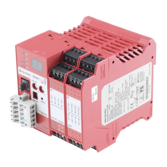
Overview Hardware The SmartGuard 600 controller features 16 digital inputs, 8 digital outputs, 4 pulse test sources, and connections for USB and DeviceNet Safety protocol. SmartGuard 600 Controller Features Number Feature Module LED Indicators Alphanumeric display Node address switches Baud rate switches... -
Page 15: Communications
Overview Safety Inputs The controller has 16 local safety inputs, which support the features described below. • Input circuit diagnosis — Test pulse sources can be used to monitor internal circuits, external devices, and external wiring. • Input on- and off-delays — You can set input time filters of 0…126 ms in multiples of the controller cycle time. -
Page 16: Configuration And Programming
Overview function simultaneously as a safety master, safety slave, and standard slave. Explicit messages can be used to read controller status information. Explicit messages set from the configuration software can be sent from the user program. The USB port can be used to program the SmartGuard controller and to configure devices on the DeviceNet network. -
Page 17: Safety Concept Of The Controller
Overview Safety Concept of the The SmartGuard 600 controller is certified for use in safety applications up to and including Safety Integrity Level (SIL) 3, Controller according to IEC 61508, and Category (CAT) 4, according to EN 954-1, in which the de-energized state is the safety state. Safety application... - Page 18 Overview Publication 1752-UM001A-EN-P - October 2006...
-
Page 19: Installing And Wiring The
Chapter Installing and Wiring the SmartGuard 600 Controller Introduction Topic Page General Safety Information Understanding Node Addressing Setting the Node Address Setting the Communication Rate Mounting the SmartGuard Controller Grounding the SmartGuard Controller Connecting a Power Supply Wiring the SmartGuard 600 Controller... - Page 20 Installing and Wiring the SmartGuard 600 Controller North American Hazardous Location Approval The following information applies when operating this Informations sur l’utilisation de cet équipement en equipment in hazardous locations environnements dangereux Products marked CL I, DIV 2, GP A, B, C, D are suitable for use in Les produits marqués CL I, DIV 2, GP A, B, C, D ne conviennent qu’à...
- Page 21 Installing and Wiring the SmartGuard 600 Controller Prevent Electrostatic Discharge ATTENTION This equipment is sensitive to electrostatic discharge, which can cause internal damage and affect normal operation. Follow these guidelines when you handle this equipment. • Touch a grounded object to discharge potential static.
-
Page 22: Understanding Node Addressing
Installing and Wiring the SmartGuard 600 Controller Understanding Node To communicate on the DeviceNet network, each device requires its own address. Follow the recommendations below when assigning Addressing addresses to the devices on your network. Node Address Recommendations Give This Device... -
Page 23: Setting The Communication Rate
Installing and Wiring the SmartGuard 600 Controller Follow these steps to set the node address. 1. Set the tens digit of the node address (decimal) by turning the left rotary switch. 2. Set the ones digit by turning the right rotary switch. -
Page 24: Mounting The Smartguard Controller
Installing and Wiring the SmartGuard 600 Controller Set the communication rate using the DIP switch on the front of the controller. Communication Rate Dip Switch DIP Switch Settings DIP Switch Pin Communication Rate 125 Kbps 250 Kbps 500 Kbps Set by software... -
Page 25: Grounding The Smartguard Controller
Installing and Wiring the SmartGuard 600 Controller The controller cannot be panel-mounted. Follow these steps to mount the controller to an EN50022-35x7.5 or EN50022-35x15 DIN rail. 1. Hook the top slot over the DIN rail. 2. Snap the bottom of the controller into position while pressing the controller down against the top of the rail. -
Page 26: Make Communication Connections
Class 2 circuits or limited voltage/current circuits defined in UL 508. The following Rockwell Automation 1606 power supplies are SELV- and PELV-compliant, and they meet the isolation and output hold-off time requirements of the SmartGuard 600 controller: • 1606-XLP30E • 1606-XLP72E •... -
Page 27: Connect To The Devicenet Port
Installing and Wiring the SmartGuard 600 Controller Connect to the DeviceNet port Follow these steps to connect to the DeviceNet port. 1. Wire the connector according to the colors on the connector. Connect Red Wire White White Wire CAN H —... -
Page 28: Wiring The Smartguard 600 Controller
Installing and Wiring the SmartGuard 600 Controller Wiring the SmartGuard 600 Use cables of 30 m (98 ft) or less. Controller General Wiring Information Wire type Copper 2 - on power, signal, and communication ports Wiring category Wire size For power supply and I/O, use 0.2…2.5 mm (12…24 AWG) -
Page 29: Wire Input Devices
Controller 24V dc Devices, such as light curtains, with current-sourcing PNP semiconductor outputs send a signal to the SmartGuard 600 controller safety input terminal and do not use a test output. Input Devices with PNP Semiconductor Outputs 4.5 mA Typical... -
Page 30: Wire Output Devices
Installing and Wiring the SmartGuard 600 Controller Wire Output Devices Serious injury may occur due to a loss of required safety ATTENTION functions. Do not connect loads beyond the rated value of safety or test outputs. Do not use test outputs as safety outputs. -
Page 31: Wiring Examples
Installing and Wiring the SmartGuard 600 Controller Wiring Examples ESTOP KM1-NC KM2-NC 11 21 12 22 E1 and E2: 24V dc Power Supplies S1: Emergency Stop Switch S2: Reset Switch (N.O. Contact) KM1 and KM2: Contactors Connect a 24V dc power supply to terminals V0 and G0, the power supply terminals for internal circuits. - Page 32 Installing and Wiring the SmartGuard 600 Controller Two-hand Switch KM1-NC KM2-NC E1 and E2: 24V dc Power Supplies S11 and S12: Two-hand Switches KM1 and KM2: Contactors Connect a 24V dc power supply to terminals V0 and G0, the power supply terminals for internal circuits.
- Page 33 Installing and Wiring the SmartGuard 600 Controller User Mode Switch E1 and E2: 24V dc Power Supplies S1: User Mode Switch Connect a 24V dc power supply to terminals V0 and G0, the power supply terminals for internal circuits. Publication 1752-UM001A-EN-P - October 2006...
- Page 34 Installing and Wiring the SmartGuard 600 Controller Publication 1752-UM001A-EN-P - October 2006...
-
Page 35: Set Up Your Devicenet Network
Chapter Set Up Your DeviceNet Network Introduction Topic Page Connect a Computer to the DeviceNet Network Commission All Nodes Browse the Network Configuration Signature Safety Reset (Optional) Set Passwords (Optional) Connect a Computer to the To access a network, either: DeviceNet Network •... -
Page 36: Configure A Driver For The Network
Set Up Your DeviceNet Network Configure a Driver for the Network 1. Start RSLinx software. 2. Click Configure Driver. 3. From the pull-down the list of Available Driver Types, add the driver for your network. Network Driver RS-232 RS-232 DF1 devices EtherNet/IP Ethernet devices DeviceNet... - Page 37 Set Up Your DeviceNet Network Follow the guidelines on page 22 when selecting node addresses for your DeviceNet network. To allow the node address to be set using the Node IMPORTANT Commissioning tool in RSNetWorx for DeviceNet, set the node address rotary switch on the controller to a value from 64…99.
-
Page 38: Browse The Network
Set Up Your DeviceNet Network Browse the Network Follow these steps to browse the network. 1. Determine your connection type. If You Are Using This Then Connection Type DeviceNet network Go to step 2. USB Port Follow these steps to configure a path to the DeviceNet network. -
Page 39: Safety Reset (Optional)
Set Up Your DeviceNet Network SmartGuard 600 Controller Configuration Signature The configuration signature is read during each browse and whenever the Device Properties dialog is launched while the software is in the Online mode. RSNetWorx for DeviceNet software compares the configuration signature in the software (offline) device configuration file to the configuration signature in the online device. -
Page 40: Publication 1752-Um001A-En-P - October
Set Up Your DeviceNet Network 1. Open the Reset Safety Device dialog by clicking on the device in the RSNetWorx for DeviceNet software graphic view and selecting Reset Safety Device from the Device menu. 2. Check the attributes you want to reset. Attribute Reset Behavior Configuration... -
Page 41: Set Passwords (Optional)
Set Up Your DeviceNet Network Set Passwords (Optional) You can protect safety devices with a password to prevent changes to the configuration of the device by unauthorized personnel. When a password is set, the following operations require the password to be typed. -
Page 42: Forgotten Passwords
Set Up Your DeviceNet Network 5. Type and confirm the new password. Passwords may be from 1…40 characters in length and are not case-sensitive. Letters, numerals, and the following symbols may be used: ‘ ~ ! @ # $ % ^ & * ( ) _ + , - = { } | [ ] \ : ; ? / . 6. -
Page 43: Chapter 4 Introduction
Chapter Manage the Safety Network Number Introduction Topic Page Safety Network Number (SNN) Formats Assignment of the Safety Network Number (SNN) Set the Safety Network Number (SNN) in All Safety Nodes Safety Network Number (SNN) Mismatch Safety Network Number (SNN) and Node Address Changes Each DeviceNet Safety device must be configured with a safety network number (SNN). -
Page 44: Time-Based Safety Network Number (Recommended)
Manage the Safety Network Number Time-based Safety Network Number (Recommended) In the time-based format, the safety network number (SNN) represents the date and time at which the number was generated, according to the personal computer running RSNetWorx for DeviceNet software. Manual Safety Network Number (SNN) In the manual format, the SNN represents typed values from 1…9999 decimal. -
Page 45: Assignment Of The Safety Network Number (Snn)
Manage the Safety Network Number Assignment of the Safety An SNN can be generated automatically via RSNetWorx for DeviceNet software or you can manually assign one. An automatically generated Network Number (SNN) SNN is sufficient and recommended for most applications. Automatic (Time-based) When a new safety device is added to the network configuration, a default SNN is automatically assigned via the configuration software,... - Page 46 Manage the Safety Network Number Follow these steps if you need to set the SNN for a particular device. 1. Click the target device in the hardware graphic view and choose Set Safety Network Number from the Device menu. 2. Choose Time-based and click Generate, or choose Manual and fill in a decimal number from 1…9999.
-
Page 47: Safety Network Number (Snn) Mismatch
Manage the Safety Network Number Safety Network Number RSNetWorx for DeviceNet software compares the offline SNN to the online SNN during each browse operation, one-shot or continuous, (SNN) Mismatch and during upload and download operations. If the SNNs do not match, RSNetWorx for DeviceNet software indicates an error with the SNN. - Page 48 Manage the Safety Network Number See Safety Reset (Optional) on page 39 for more information on the Safety Reset function. After the safety reset, the node address can be changed in RSNetWorx for DeviceNet software by double-clicking the safety device’s node address in the graphic view. After changing the node address, right-click the device and click Download to Device to restore the safety device’s SNN and configuration.
-
Page 49: Chapter 5 Introduction
Chapter Configure Local I/O Introduction Topic Page Configure Local Safety Inputs Configure Local Test Outputs Configure Local Safety Outputs Configure Local Safety The controller has 16 local safety inputs that support the following features. Inputs • Input circuit diagnosis — Test pulse sources can be used to monitor internal circuits, external devices, and external wiring. - Page 50 Configure Local I/O 2. Select the Local Input/Test Output tab. 3. Set the Error Latch Time. The error latch time applies to all safety inputs and test outputs. It sets the time to latch the error state when an error occurs in an input or output.
- Page 51 Configure Local I/O 6. Set the Channel Mode for the safety input. Input Channel Mode Settings Channel Mode Description Not used The input channel is not connected to an external device. This is the default. Test pulse from Use this mode when you are achieving a Category 4 input test output circuit.
-
Page 52: Example: Input Channel As Test Pulse From Test Output
Configure Local I/O The controller supports function blocks with functionality equivalent to Dual Channel mode. If Dual Channel mode is set in a function block, the safety input terminal can be set to Single Channel mode. 9. Specify an On Delay time and an Off Delay time. The valid range is 0…126 ms, but the delay time must be a multiple of the cycle time. -
Page 53: Automatic Adjustment Of On- And Off-Delay Times
Configure Local I/O Automatic Adjustment of On- and Off-delay Times If parameters that affect the cycle time are changed after the on- and off-delays have been set, you may not be able to close the Controller Properties dialog because of an error in the parameter settings. If this occurs, you can re-adjust the on-and off-delay times based on the cycle time using the Adjust valid ON/OFF delays with cycle time value button on the Local Input/Test Output tab. - Page 54 Configure Local I/O Follow these steps to configure a test output. 1. Right-click the SmartGuard controller and choose Properties. 2. Select the Local Input/Test Output tab. 3. Set the Error Latch Time. The error latch time applies to all safety inputs and test outputs. It sets the time to latch the error state when an error occurs in an input or output.
- Page 55 Configure Local I/O 5. Select a test output terminal and click Edit. 6. Type an I/O Comment. The I/O comment typed here is used as an I/O tag name in the Logic Editor. 7. Choose a Test Output Mode from the pull-down list. Test Output Mode Settings Test Output Mode Description...
-
Page 56: Configure Local Safety Outputs
Configure Local I/O Configure Local Safety The controller has eight local safety outputs that support the functions listed below. Outputs • Output circuit diagnosis — Test pulses can be used to diagnose the controller’s internal circuits, external devices, and external wiring. - Page 57 Configure Local I/O 4. Select a safety output terminal and click Edit. 5. Type an I/O Comment. The I/O comment typed here is used as an I/O tag name in the Logic Editor. 6. Set the Channel Mode for the safety output. Output Channel Mode Settings Channel Mode Description...
- Page 58 Configure Local I/O 7. Set the Dual Channel mode for the safety output. Setting Dual Channel mode enables an error to be detected if the two outputs from a user program are not equivalent. If an error is detected in one of two outputs circuits, both outputs to the device will become inactive.
-
Page 59: Chapter 6 Introduction
Chapter Configure Your Controller for DeviceNet Communications Introduction The SmartGuard controller can function simultaneously as a safety master, safety slave, or standard slave. Topic Page Set Up the Controller as a Safety Master Set Up the Controller as a Safety Slave Set Up the Controller as a Standard Slave Set Up the Controller as a As a Safety master, the controller can perform safety I/O... -
Page 60: Network
Configure Your Controller for DeviceNet Communications SmartGuard Controller as the Safety Master SmartGuard Controller - Safety Originator Safety Connections CIP Safety I/O Modules Configure CIP Safety I/O Targets on the DeviceNet Network To configure your module, double-click on the module in the graphic view or right-click on the module and select Properties. - Page 61 Configure Your Controller for DeviceNet Communications Standard Input and Output Parameters 1791DS modules shown here support standard data as well as safety data. Configure standard input and output parameters using the Parameters tab on the Module Properties dialog. Other devices may have different configuration options.
-
Page 62: Configure Safety I/O Connections
Configure Your Controller for DeviceNet Communications Configure Safety I/O Connections Safety I/O connections are used to exchange data automatically with the safety slaves without user programming. To perform safety I/O communications with other slaves, you must configure the connection to the SmartGuard controller. 1. - Page 63 Configure Your Controller for DeviceNet Communications 4. Select Configuration signature must match. This selection directs the SmartGuard controller to verify that the target safety device contains the correct configuration before opening the safety connection. If you do not choose Configuration signature must match, IMPORTANT you are responsible for verifying the safety integrity of your system by some other means.
-
Page 64: Set Up The Controller As A Safety Slave
Configure Your Controller for DeviceNet Communications 7. Set the Advanced Safety Connection Properties (if required). • Timeout Multiplier – The Timeout Multiplier determines the number of RPIs to wait for a packet before declaring a connection timeout. This translates into the number of messages that may be lost before a connection error is declared. -
Page 65: Create Safety Slave I/O Data
Configure Your Controller for DeviceNet Communications SmartGuard Controller as Safety Slave and Safety Originator Safety SmartGuard Controller GuardLogix System Safety Slave Control Safety PLC Safety Originator System Safety Originator Safety Communications Safety Communications CIP Safety I/O Modules When the controller operates as a safety slave, you can configure the safety slave assemblies to transfer local I/O data (monitor data), controller and I/O status data, and distributed I/O data to a safety master. - Page 66 Configure Your Controller for DeviceNet Communications 4. In the Edit Safety Slave I/O dialog, choose the I/O Type, either Safety Slave Input or Safety Slave Output. I/O Type Safety Data Direction Safety Slave Input SmartGuard controller safety slave —> safety master Safety Slave Output Safety master —>...
- Page 67 Configure Your Controller for DeviceNet Communications 6. You can add local I/O monitor data for Safety Input types by checking the appropriate Local I/O Monitor checkbox. Tag Name Data Size Attribute Type Local Input Monitor 1 (Inputs 0…7) Byte Safety Local Input Monitor 2 (Inputs 8…15) Byte Safety...
- Page 68 Configure Your Controller for DeviceNet Communications 10. You can create a tag name for each bit in an I/O assembly. a. Select the applicable assembly and click Edit Comment. b. Type a comment for each bit in the tag. The tag name comments typed here are displayed in the Logic Editor.
-
Page 69: Using The Safety Generic Profile In Rslogix 5000 Software
Configure Your Controller for DeviceNet Communications Using the Safety Generic Profile in RSLogix 5000 Software You can connect to the SmartGuard slave controller using the safety generic profile in RSLogix 5000 software. Follow these steps to connect to the controller. 1. - Page 70 Configure Your Controller for DeviceNet Communications 5. On the Module Definition tab, select the Connection tab. 6. Set the safety input and output parameters using the following tables. Input Assemblies When the Safety Set the Generic Profile Set the Generic Profile Slave Input Name is Input Instance Number Output Instance Number...
-
Page 71: Smartguard Controller To Smartguard Controller Safety Interlocking
Configure Your Controller for DeviceNet Communications SmartGuard Controller to SmartGuard Controller Safety Interlocking Safety interlocking lets two SmartGuard controllers to share safety data and make decisions based on one another’s inputs or outputs. Safety interlocking lets you distribute your safety control to multiple SmartGuard controllers that work together. - Page 72 Configure Your Controller for DeviceNet Communications 3. From the pull-down, choose the safety I/O assembly you want to use. 4. Click Add. 5. Now the SmartGuard controller acting as the safety master will be able to read the other SmartGuard controller’s inputs, 0…7. Publication 1752-UM001A-EN-P - October 2006...
-
Page 73: Set Up The Controller As A Standard Slave
Configure Your Controller for DeviceNet Communications Set Up the Controller as a As a standard slave, the controller can perform standard I/O communication with 1 standard master for up to 2 connections, using Standard Slave up to 16 bytes per connection. The SmartGuard controller can also respond to explicit standard messages. - Page 74 Configure Your Controller for DeviceNet Communications 3. Configure the slave controller to either clear or hold the last data for an input assembly that the slave controller transmits to the standard master when: • the slave controller changes from Run to Idle mode. •...
- Page 75 Configure Your Controller for DeviceNet Communications 6. You can add status information for Input types by checking the Status checkboxes (optional). When the I/O type is Input, you can include the following status information in the I/O assembly. Tag Name Data Size Attribute Type General Status...
- Page 76 Configure Your Controller for DeviceNet Communications 11. You can create a tag name for each bit in an I/O assembly. a. Select the applicable assembly and click Edit Comment. b. Type a comment for each bit in the tag. The tag name comments typed here are displayed in the Logic Editor.
-
Page 77: Add The Smartguard Standard Slave To The Standard Master's Scanlist
Configure Your Controller for DeviceNet Communications Add the SmartGuard Standard Slave to the Standard Master’s Scanlist To make the standard slave I/O assemblies available to the standard master, add the SmartGuard standard slave controller to the master’s scanlist. Refer to the user documentation for your standard master for information on configuring your specific device. - Page 78 Configure Your Controller for DeviceNet Communications Publication 1752-UM001A-EN-P - October 2006...
-
Page 79: Chapter 7 Introduction
Chapter Set Controller Modes Introduction Topic Page Set Automatic Execution Mode (Optional) Set Standalone Communication Mode (Optional) Set Automatic Execution The controller can be configured for Normal mode or Automatic Execution mode. Set the Automatic Execution mode only after the Mode (Optional) system has been configured. -
Page 80: Set Standalone Communication Mode (Optional)
Set Controller Modes 3. Choose either Normal Mode or Automatic Execution Mode. Mode Description Normal The controller starts in Idle mode when the power supply is turned on. You must use RSNetWorx for DeviceNet software to change to Execute mode by clicking Change Mode on the Mode/Cycle Time tab of the Controller Properties dialog. -
Page 81: Change Controller Mode
Set Controller Modes 3. In RSNetWorx for DeviceNet software, right-click the controller and choose Properties. 4. Select the Mode/Cycle Time tab. 5. Choose Disable (Stand Alone Mode) and click OK. Change Controller Mode Follow these steps to change the controller mode. 1. - Page 82 Set Controller Modes Publication 1752-UM001A-EN-P - October 2006...
-
Page 83: Introduction
User-defined Function Blocks Additional Resources The Logic Editor You program the SmartGuard 600 controller using the Logic Editor in RSNetWorx for DeviceNet software. The Logic Editor consists of a object list, where function blocks, I/O tags, and other programming elements are registered, and a workspace, where programming is performed. -
Page 84: Programming Basics
Create Your Application Program You can password-protect your application program to prevent unauthorized editing, verification, or printing of programs. To create a password, follow these steps. 1. On the Logic tab of the Controller Properties dialog, check the Enable Password checkbox. 2. -
Page 85: Logic Functions And Function Blocks
Create Your Application Program Logic Functions and Function Blocks A maximum of 254 logic functions and function blocks can be used. Supported Logic Instructions and Function Blocks Function Blocks Logic Instructions • NOT • Reset • AND • Restart • OR •... - Page 86 Create Your Application Program In the object list, I/O tags are displayed with symbols to indicate how they are configured. Input Tag Symbols Input Mode Symbol Channel Mode Symbol Not Used Single None Test Pulse From Test Out Dual Channel Equivalent Used As Safety Input Dual Channel Complementary Used As Standard Input...
-
Page 87: Output Tags
Create Your Application Program Output Tags Output tags reflect the status of outputs from these I/O areas: • The controller’s local terminals • Output area of safety slaves registered as communications partners • Output area reflected from safety master data •... -
Page 88: I/O Comment Function
Create Your Application Program I/O Comment Function The I/O comment is an optional name, consisting of up to 32 ASCII characters that can be registered in the controller for each I/O terminal using RSNetWorx for DeviceNet software. These I/O comments can be used in the object list of the Logic Editor as I/O tags, simplifying programming. -
Page 89: Create A Function Block Program
Create Your Application Program Create a Function Block To create a program using function blocks, you create connections from the function block to input and output tags. Program Add an Input or Output Tag Follow these steps to add a tag. 1. -
Page 90: Connect The Tags To The Function Block
Create Your Application Program Place a Function Block Connect the Tags to the Function Block To connect the I/O tags to the function block, click the source connector ( ) and drag it to the destination connector ( ■ ■ Connect Tags to Function Blocks Edit Function Block You can edit function blocks by changing parameter settings,... -
Page 91: In/Out Settings
Create Your Application Program Parameter Tab In/Out Settings You can edit the Number of Inputs, Number of Outputs, and, in some cases, the Fault Present settings for many instructions. In/Out Setting Tab Number of Inputs The number of inputs for logic functions can be increased or the optional input to function blocks can be enabled. -
Page 92: Optional Output Point Selections
Create Your Application Program Fault Present Bit You can enable the Fault Present diagnostic-status bit in some function blocks by selecting the checkbox located on the In/Out Setting tab of the Function Block Properties dialog. If the Use Fault Present checkbox is checked, an additional Fault Present output is displayed on the function block. -
Page 93: Find Function Blocks With Open Connections
Create Your Application Program Comment Tab Find Function Blocks with Newly created programs containing function blocks with open inputs or outputs cannot be downloaded. All I/O must be used. Open Connections Function Block With Open Connections Open Connection To find all open connections in the Logic Editor, choose Edit>Search OpenConnection. -
Page 94: Programming On Multiple
Create Your Application Program Programming on Multiple The SmartGuard 600 controller supports up to 32 pages of programming logic. Pages To create a new page, click the Add Page icon Use jump addresses to connect logic between pages. A SmartGuard 600 controller program can contain up to 128 jump addresses. -
Page 95: Save The Program
Create Your Application Program Save the Program Follow these steps to save your application program. 1. Choose File>Apply. The program is saved temporarily in RSNetWorx for DeviceNet software. 2. Exit the Logic Editor by choosing File>Exit. 3. Click OK on the Edit Device Parameters dialog. If you do not click OK or you click Cancel, none of your program changes will be saved. -
Page 96: Monitor The Program Online
Create Your Application Program Monitor the Program Online The I/O tag values and signal states of connections with function blocks can be monitored online in the Logic Editor. Make sure that RSNetWorx for DeviceNet software is connected to the network and that the controller being monitored is in Run mode before starting online program monitoring. -
Page 97: Program Execution Sequence
Create Your Application Program Program Execution The order of execution of function blocks is automatically set by the Logic Editor and displayed in the right-hand corner of each function Sequence block. Example Program In this example, the execution order is: 1. -
Page 98: User-Defined Function Blocks
Create Your Application Program User-defined Function The Logic Editor lets you create user-defined function blocks that consist of existing function block logic. Once created, these function Blocks blocks are stored in a user-defined library and can be used in any SmartGuard controller application. - Page 99 Create Your Application Program 6. Write the logic for the function block. 7. Choose File>Save and type a name for the function block, when prompted. 8. Add the new function block to your application logic. Publication 1752-UM001A-EN-P - October 2006...
-
Page 100: Password Protect User-Defined Function Blocks
Create Your Application Program If you wish to edit your user-defined function block, it cannot be used in the current application. If it is, the edit option is unavailable. Always download programs with user-defined function blocks IMPORTANT to the controller, check their configuration, and verify their operation before using them in an application. -
Page 101: Reuse User-Defined Function Block Files
Create Your Application Program We recommend using a password to protect user-defined function blocks that have been tested to prevent unauthorized or unintentional changes once the function block has been allocated in a user program. Reuse User-defined Function Block Files Project files (*.dnt) and user-defined function block files (*.fbd) exist as separate files. -
Page 102: Precautions For Reusing User-Defined Function Blocks
Create Your Application Program 6. Import the user-defined function block. a. In RSNetWorx for DeviceNet software, create a new project and add a SmartGuard controller. b. Right-click the controller, choose Properties and select the Logic tab. c. Click Edit to start the Logic Editor. d. -
Page 103: Additional Resources
Create Your Application Program Outcomes Without Function Block Files Action File Outcome Verification Required Program verification can be completed even without the function block file once the file is downloaded to the controller, but the function block configuration cannot be checked. Edit the program Required A warning message will appear if the Logic Editor is... - Page 104 Create Your Application Program Publication 1752-UM001A-EN-P - October 2006...
-
Page 105: Download And Verify
Chapter Download and Verify Introduction Topic Page Download the DeviceNet Network Configuration Verify Your DeviceNet Safety Configuration Start the Safety Device Verification Wizard Determine if Devices Can Be Verified Select Devices to Verify Review the Safety Device Verification Reports Lock Safety Devices View the Safety Device Verification Wizard Summary Download the DeviceNet Before you download, you must go online to the DeviceNet network... - Page 106 Download and Verify Follow these steps to download the DeviceNet network configuration. 1. Go online by clicking the online icon. 2. Browse to the DeviceNet network and click OK at the prompt. During each browse operation, RSNetWorx for DeviceNet software reads the following attributes of each device. Safety Attribute Description Safety Network Number...
-
Page 107: Verify Your Devicenet Safety Configuration
Download and Verify If none of your devices are password-protected or safety-locked, you can choose Download to Network from the Network menu to download your configuration to the network. However, this process skips devices that are password-protected or safety-locked. Verify Your DeviceNet Safety Configuration Before running the Safety Device Verification Wizard, you IMPORTANT... -
Page 108: Determine If Devices Can Be Verified
Download and Verify Determine if Devices Can When the Safety Device Verification Wizard browses the network, it checks the safety status of the devices on the network to determine if Be Verified the devices can be verified. If any devices are in a state that prevents the wizard from continuing the verification process, the Unable to verify the listed devices dialog appears listing those devices and their current status, including a device icon overlaid with a status icon. -
Page 109: Select Devices To Verify
Download and Verify To skip the devices listed and continue the verification process for other safety devices on the network, click Next. Select Devices to Verify Choose which devices to verify using the checkboxes in the Verify column of the Verify Safety Device Configuration dialog. You can select only the devices whose status is Ready to be verified. - Page 110 Download and Verify Click Next to begin the upload and compare process. If you click Next without selecting a device to verify, the wizard checks whether any devices were verified or are ready to be locked in this execution of the wizard. Then the wizard displays Devices were verified the Review dialog listing those...
-
Page 111: Review The Safety Device Verification Reports
Download and Verify Review the Safety Device The Review page displays safety devices with status of either Verify FAILED or Ready to be Safety Locked. Verification Reports 1. Click Review in the Report column to launch the device’s HTML report in your default browser. 2. -
Page 112: Lock Safety Devices
Download and Verify Lock Safety Devices Before you lock your safety device configurations, you must IMPORTANT perform all of the verification steps required for your application. 1. Choose which devices to safety-lock by checking the checkbox in the Lock column for each device that is ready to be safety-locked. -
Page 113: View The Safety Device Verification Wizard Summary
Download and Verify View the Safety Device Before closing, the wizard displays a summary of all the safety devices that were safety-locked, the number of safety devices that still need to Verification Wizard be safety-locked, and lets you display the verified and safety-locked Summary state of all of the safety devices on the network. -
Page 114: Publication 1752-Um001A-En-P - October
Download and Verify Publication 1752-UM001A-EN-P - October 2006... -
Page 115: Introduction
Reset Errors and Corrective Actions Mode Change Errors and Corrective Actions LED Indicators The SmartGuard 600 controller features LED indicators for module status, network status, lock status, communication status, and individual input and output status. For a description of the color and status combinations of the LED indicators and recommended actions, see Appendix A. -
Page 116: Monitor I/O Power Supply Input
Monitor Status and Handle Faults Safety tab of the controller Properties dialog in RSNetWorx for DeviceNet software. You can use the configuration signature to verify that the program and configuration of the controller has not been changed. Explanation of Display Operation Status Display Operating mode: Run... -
Page 117: Monitor I/O Maintenance Information
Monitor Status and Handle Faults Monitor I/O Maintenance You can configure a maintenance mode and alarm threshold for each local input, test output, and local output terminal using the Information Maintenance tab of the Controller Properties dialog in RSNetWorx for DeviceNet software. -
Page 118: Configure A Maintenance Monitoring Mode
Monitor Status and Handle Faults Calculating Total On-time With 1.5 Second On Pulses EXAMPLE In this example, the bit is actually on for 1.5 s x 2 = 3 s, but the bit is on 4 times when status is checked, so the total on-time is measured as 4 s. -
Page 119: Clear The Maintenance Values
Monitor Status and Handle Faults 4. Select the desired terminal and click Edit. 5. On the Edit Maintenance Config dialog choose the Detection mode, either Count or Time. 6. Type an alarm threshold value for the specified Detection mode. Detection Mode Valid Range for Values Time 0…4,294,967,295 seconds... -
Page 120: View I/O Status Data
Monitor Status and Handle Faults 2. Click Clear on the Maintenance Monitor dialog. View I/O Status Data When the controller operates as a safety slave or a standard slave target, status information can be added to the first line of the transmit data. -
Page 121: General Status Data
Monitor Status and Handle Faults General Status Data The general status flags are non-safety attributes that indicate system status. General Status Data Details Bit Name Description Input Power Supply Indicates the status of the power supply voltage for Voltage Status Flag inputs. -
Page 122: Local Input Status
Monitor Status and Handle Faults Local Input Status When the bit is on, the status of the input is normal. When the bit is off, an error has been detected Local Safety-Input Terminal Status Byte Bit 7 Bit 6 Bit 5 Bit 4 Bit 3 Bit 2... -
Page 123: Controller Connection Status (Safety Slave Function)
Monitor Status and Handle Faults Controller Connection Code Status Corrective Action Status (Safety Slave 00:0001 Normal The safety I/O connection status is normal. Function) communications 01:0001 Safety I/O The safety I/O connection has timed out. Check the Connection following: Timeout •... - Page 124 Monitor Status and Handle Faults Code Status Corrective Action 01:0117 Connection Path Two or more single-cast safety I/O connections or a Error multi-cast safety I/O connection with a different RPI has been set for a safety slave I/O. To share one safety slave I/O on a safety slave with more than one safety master, make the RPI all the same and set the connection type to multi-cast.
-
Page 125: Error Categories
Monitor Status and Handle Faults Code Status Corrective Action 01:080C Safety Signature The safety signature for the safety slave monitored by the Match safety master does not match the safety signature of the safety slave itself. Reset the safety slave to default setting then download the device parameters again. -
Page 126: Error History Table
Monitor Status and Handle Faults Error History Table When an error is detected, a record is made in the error history table in the controller’s RAM. If the number of error records exceeds the maximum of 100, the oldest records are deleted sequentially and the most recent error data is stored as a new record. -
Page 127: Error History Messages And Corrective Actions
Monitor Status and Handle Faults 2. Select the Error History tab. One Error History Record Status When the Error Occurred a. Click Save to save the error history data, which can also be saved in a separate CSV file. b. Click Clear to erase the error history saved in the controller. c. - Page 128 Monitor Status and Handle Faults DeviceNet Communication Error Messages Message Description Corrective Action Switch Setting Mismatch Switch settings do not match. Check that the node address is the same as the address in the last configuration. If not, change back to the original node address or reconfigure.
- Page 129 Monitor Status and Handle Faults DeviceNet Communication Error Messages Message Description Corrective Action EM Transmission Error Unable to transmit because the Make sure the communication rate of all nodes is the same. (Device Offline) local device is not on the network. Make sure the cable lengths of main or branch lines are not too long.
- Page 130 Monitor Status and Handle Faults Safety Input Error Messages Message Description Corrective Action External Test Signal A failure has occurred in the external wiring at Make sure the input signal wire is not contacting the power Failure at Safety Input the safety input.
-
Page 131: Download Errors And Corrective Actions
Monitor Status and Handle Faults Safety Output Error Messages Message Description Corrective Action Over Current Detected at Overcurrent was detected at the safety Make sure there is no overcurrent for the output. Safety Output output. Make sure the output signal wire does not have an earth Short Circuit Detected at A short-circuit was detected at the safety fault. - Page 132 Monitor Status and Handle Faults RSNetWorx for DeviceNet Software Download Error Messages and Corrective Actions Message Description Corrective Action An error was found An inconsistency exists between Correct the parameters settings. Check for the following: during parameter check. configuration parameters. •...
-
Page 133: Reset Errors And Corrective Actions
Monitor Status and Handle Faults RSNetWorx for DeviceNet Software Download Error Messages and Corrective Actions Message Description Corrective Action Message could not be A connection to the controller Make sure that power to the device has been turned on and try sent. - Page 134 Monitor Status and Handle Faults RSNetWorx for DeviceNet Software Reset Error Messages and Corrective Actions Message Description Corrective Action Access error. The password used does not Make sure the correct password is being used. provide authority to change configurations. The device cannot be 1.
-
Page 135: Mode Change Errors And Corrective Actions
Monitor Status and Handle Faults Mode Change Errors and The controller may return an error response when you change modes. Use the messages displayed in RSNetWorx for DeviceNet software to Corrective Actions identify the error. RSNetWorx for DeviceNet Software Mode-Change Error Messages and Corrective Actions Message Description Corrective Action... - Page 136 Monitor Status and Handle Faults Publication 1752-UM001A-EN-P - October 2006...
-
Page 137: Status Led Indicators
Appendix Status Indicators LED indicators are not reliable indicators for safety functions. ATTENTION They should be used only for general diagnostics during commissioning and troubleshooting. Do not use LED indicators as operational indicators. Status LED Indicators Use this table to interpret the color and status combinations of the LED indicators and take recommended actions where applicable. - Page 138 Status Indicators LED Indicator Descriptions LED Indicator Color/ Description Recommended Action State The controller is not online or may 1. Cycle the DeviceNet power supply. not have power from the 2. Check external wiring. DeviceNet network. 3. Take corrective actions for noise. 4.
-
Page 139: Identifying Errors Using Status Indicators
Status Indicators Identifying Errors Using Use these tables to interpret the color and status combinations of the LED and alphanumeric display indicators and take corrective action Status Indicators where applicable. Critical Errors Indicators Error Log Cause Corrective Action Alphanumeric Display Code None Critical hardware fault. - Page 140 Status Indicators Nonfatal Errors Indicators Error Log Cause Corrective Action Alphanumeric Display Code Red, Safety I/O Safety I/O connection could not be Make sure the slave device is Flashing Connection established. configured and in a normal Establishment operational state. Failure Red, Invalid Slave Device Invalid slave device due to...
- Page 141 Status Indicators Nonfatal Errors Indicators Error Log Cause Corrective Action Alphanumeric Display Code Target External Test Signal An external wiring error has 1. Check that the signal wire: terminal Failure at Safety occurred at a safety input. • is not contacting the power Red, on Input source (positive side).
- Page 142 Status Indicators Nonfatal Errors Indicators Error Log Cause Corrective Action Alphanumeric Display Code Target Overcurrent An overcurrent was detected at 1. Make sure there is no terminal Detected at Safety the safety output. overcurrent for the output. Red, on Output 2.
-
Page 143: Introduction
Appendix Logic Functions Command Reference Introduction This appendix describes the logic functions used for programming. Topic Page NOT Instruction AND Instruction OR Instruction Exclusive OR Instruction Exclusive NOR Instruction Routing Instruction Reset Set Flip-flop (RS-FF) Instruction Multi-connector Instruction Comparator Instruction NOT Instruction The outcome is the inverse of the input. -
Page 144: And Instruction
Logic Functions Command Reference AND Instruction The output is the logical AND of up to eight input conditions. The number of inputs can be set using the In/Out Setting tab in the Function Block Properties dialog. The default setting is 2 inputs. AND Instruction Diagram Input 1 Output 1... - Page 145 Logic Functions Command Reference Truth Table for Four-input AND Evaluation Input 1 Input 2 Input 3 Input 4 Output 1 Truth Table for Five-input AND Evaluation Input 1 Input 2 Input 3 Input 4 Input 5 Output 1 Truth Table for Six-input AND Evaluation Input 1 Input 2 Input 3...
-
Page 146: Or Instruction
Logic Functions Command Reference Truth Table for Seven-input AND Evaluation Input 1 Input 2 Input 3 Input 4 Input 5 Input 6 Input 7 Output 1 Truth Table for Eight-input AND Evaluation Input 1 Input 2 Input 3 Input 4 Input 5 Input 6 Input 7 Input 8 Output 1 OR Instruction The Output is the logical OR of up to eight input conditions. -
Page 147: Or Instruction Diagram
Logic Functions Command Reference OR Instruction Diagram Input 1 Output 1 Input 2 OR Instruction Truth Tables In the truth table, 0 is off and 1 is on. Lowercase x is don’t care. Truth Table for One-input OR Evaluation Input 1 Output 1 Truth Table for Two-input OR Evaluation Input 1... - Page 148 Logic Functions Command Reference Truth Table for Four-input OR Evaluation Input 1 Input 2 Input 3 Input 4 Output 1 Truth Table for Five-input OR Evaluation Input 1 Input 2 Input 3 Input 4 Input 5 Output 1 Truth Table for Six-input OR Evaluation Input 1 Input 2 Input 3...
-
Page 149: Exclusive Or Instruction
Logic Functions Command Reference Truth Table for Seven-input OR Evaluation Input 1 Input 2 Input 3 Input 4 Input 5 Input 6 Input 7 Output 1 Truth Table for Eight-input OR Evaluation Input 1 Input 2 Input 3 Input 4 Input 5 Input 6 Input 7 Input 8 Output 1 Exclusive OR Instruction The output is the exclusive OR of the input conditions. -
Page 150: Exclusive Or Truth Table
Logic Functions Command Reference Exclusive OR Truth Table In the truth table, 0 is off and 1 is on. Truth Table for Exclusive OR Evaluation Input 1 Input 2 Output 1 Exclusive NOR Instruction The output is an exclusive NOR of the input conditions. Exclusive NOR Instruction Diagram Input 1 Output 1... -
Page 151: Routing Instruction
Logic Functions Command Reference Routing Instruction The Routing instruction routes one input signal to a maximum of eight output signals. It is used to output a signal to more than one physical address, such as an output tag. The number of outputs can be set using the I/O Setting tab in the Function Block Properties dialog. -
Page 152: Reset Set Flip-Flop Instruction Diagram
Logic Functions Command Reference Reset Set Flip-flop Instruction Diagram Input Output Enable Input Output Enable Reset Fault Present Reset Default Connections Maximum Inputs for Reset Set Flip-Flop Function Reset Set FIip-flop Error Handling Use this table to diagnose and reset a discrepancy error condition in the RS Flip-flop instruction. -
Page 153: Multi-Connector Instruction Diagram
Logic Functions Command Reference The number of inputs and outputs can be increased to eight on the I/O Settings tab of the Function Block Properties dialog in RSNetWorx for DeviceNet software. The default setting is one. Multi-connector Instruction Diagram Input 1 Output 1 Input 1 Output 1... -
Page 154: Comparator Instruction
Logic Functions Command Reference Comparator Instruction The comparator instruction compares the specified input signals of up to eight inputs with the configured comparison pattern and turns on the Output 1 signal when all of the input signals match the comparison pattern. The Output 1 signal turns off when the input signals no longer match the comparison value. -
Page 155: Comparator Instruction Truth Table
Logic Functions Command Reference Comparator Instruction Truth Table In the truth table, 0 is off and 1 is on. CV is the comparison value. An X indicates that the status of the input (match or don’t match) is not applicable. Truth Table for Comparator Instruction Input 8 Input 7 Input 6 Input 5 Input 4 Input 3 Input 2 Input 1 Output 1 ≠CV for... -
Page 156: Comparator Instruction Timing Chart
Logic Functions Command Reference Comparator Instruction Timing Chart The horizontal dashed lines in the chart represent the comparison values (CV) for each input. 1. Output 1 turns on when all of the input signals match the comparison value. 2. Output 1 turns off when any of the input signals does not match the comparison value. - Page 157 Appendix Function Blocks Command Reference Introduction This appendix describes the function blocks used for programming. Topic Page Reset Function Block Restart Function Block Emergency Stop (ESTOP) Light Curtain (LC) Function Block Safety Gate Monitoring Function Block Two-hand Control Function Block OFF-delay Timer Function Block ON-delay Timer Function Block User Mode Switch Function Block...
-
Page 158: Reset Function Block Parameters
Function Blocks Command Reference The Output Enable signal turns on if the Reset signal is correctly received while the Monitored Input condition to the Reset function block is on. This function block can be used to prevent the machine from automatically resetting when power to the controller is turned on, when the operating mode is changed from Idle mode to Run mode, or when a signal from a safety input device turns on. -
Page 159: Reset Function Block Timing Charts
Function Blocks Command Reference Reset Function Block Timing Charts Low-High-Low Reset Signal Monitored Input Optional Input (N) Reset Output Enable Static Release Reset Required Indication Idle to Run Rising Edge Reset Signal Monitored Input Optional Input (N) Reset Output Enable Static Release Reset... -
Page 160: Restart Function Block Parameters
Function Blocks Command Reference The number of inputs can be increased from two to eight on the I/O Settings tab of the Function Block Properties dialog in RSNetWorx for DeviceNet software. The default number of inputs is two. The Output Enable signal turns on if the Restart signal is correctly received while the Monitored Input condition to the Restart function block is on. -
Page 161: Restart Function Block Timing Charts
Function Blocks Command Reference Restart Function Block Timing Charts Low-High-Low Restart Signal Monitored Input Optional Input (N) Restart Output Enable Static Release Restart Required Indication Idle to Run Rising Edge Restart Signal Monitored Input Optional Input (N) Restart Output Enable Static Release Restart... -
Page 162: Estop Function Block Parameters
Function Blocks Command Reference active. The Output Enable turns off if the inputs become inactive or if an error is detected for the function block. A manual reset function is required for emergency stop IMPORTANT applications. When using the Emergency Stop Pushbutton function block, you must also use the Reset function block. -
Page 163: Estop Function Block Error Handling
Function Blocks Command Reference Truth Table for ESTOP Function Block Single Channel Dual Channel Equivalent Dual Channel Complementary Input 1 Output Input 1 Input 2 Output Input 1 Input 2 Output (NC) Enable (NC) (NC) Enable (NC) (NO) Enable ESTOP Function Block Error Handling A discrepancy error is generated when one of the inputs is not in it’s correct state for longer than the Discrepancy Time. -
Page 164: Estop Function Block Timing Chart
Function Blocks Command Reference ESTOP Function Block Timing Chart The chart shows the I/O timing when the function block is set up as Dual Channel Equivalent. Input 1 (NC) Input 2 (NC) Output Enable Discrepancy Error Fault Present Idle to Run Discrepancy Time Light Curtain (LC) Function Light Curtain Function Block Diagram... -
Page 165: Light Curtain Function Block Parameters
Function Blocks Command Reference Light Curtain Function Block Parameters Set these parameters for the LC function block. LC Function Block Parameters Parameter Valid Range Default Setting Input Type Dual Channel Equivalent Dual Channel Equivalent Dual Channel Complementary Discrepancy Time 30 ms 0…30 s in 10 ms increments. -
Page 166: Light Curtain Function Block Timing Chart
Function Blocks Command Reference Use this table to diagnose and reset a discrepancy error condition in the LC function block. Error Detection and Reset for LC Function Block Error Status When an Error Occurs To Reset the Error Condition Condition Output Enable Fault Error... -
Page 167: Outputs
Function Blocks Command Reference The Safety Gate Monitoring function monitors the status of a safety gate, using input signals from a safety door switch or safety limit switch connected to the door. The Output Enable signal turns on if the inputs from the switch being monitored are active. -
Page 168: Safety Gate Monitoring Function Block Parameters
Function Blocks Command Reference If enabled, the safety gate test must be executed under the following conditions: • Startup – The safety gate test must be executed when the controller is started, that is, when the operating mode changes from Idle to Run. If the test ends normally, the Output Enable signal turns on. -
Page 169: Safety Gate Monitoring Function Block Truth Tables
Function Blocks Command Reference Safety Gate Monitoring Function Block Truth Tables In the truth tables, 0 is off and 1 is on. Truth Table for Single Channel and Dual Channel (1 Pair) Safety Gate Monitoring Function Block Single Channel Dual Channel Equivalent Dual Channel Complementary Input 1 Output... -
Page 170: Safety Gate Monitoring Function Block Error Handling
Function Blocks Command Reference Safety Gate Monitoring Function Block Error Handling A discrepancy error is generated when one of the inputs is not in its correct state for longer than the discrepancy time. For example, in Dual Channel Equivalent mode, both inputs must be active (on) within the discrepancy time or an error occurs. -
Page 171: Publication 1752-Um001A-En-P - October
Function Blocks Command Reference Safety Gate Monitoring Function Block Timing Charts Single Channel With Function Test Enabled Input 1 Function Test Signal Function Test Required Output Enable Function Test Error Fault Present Idle to Run Dual Channel Equivalent With Function Test Disabled Input 1 (NC) Input 2 (NC) Output... -
Page 172: Two-Hand Control Function Block
Function Blocks Command Reference Two-hand Control Function Two-hand Control Function Block Diagrams Block Input 1 Input 1 (pair 1 - NO) (pair 1 - NO) Output Output Enable Input 2 Input 2 Enable (pair 1 - NC) Discrepancy Error (pair 1) (pair 1 - NC) Input 3 Input 3... -
Page 173: Two-Hand Control Function Block Parameters
Function Blocks Command Reference Two-hand Control Function Block Parameters Set these parameters for the two-hand control function block. Two-hand Control Function Block Parameters Parameter Range Default Discrepancy Time Input Pair 1 30 ms … 500 ms in 10 ms increments The discrepancy times must be equal to Discrepancy Time Input Pair 2 or greater than the cycle time of the... -
Page 174: Two-Hand Control Function Block Error Handling
Function Blocks Command Reference Two-hand Control Function Block Error Handling A discrepancy error is generated when one of the inputs is not in its correct state for longer than the discrepancy time. For example, in Dual Channel Equivalent mode, both inputs must be active (on) within the discrepancy time or an error occurs. -
Page 175: Off-Delay Timer Function Block
Function Blocks Command Reference OFF-delay Timer Function OFF-delay Timer Function Block Diagram Block Output Enable Input The OFF-delay timer function block performs a timer operation for an OFF-delay set in 10 ms increments. The range for this delay is from 0 ms…300 seconds. -
Page 176: On-Delay Timer Function Block Timing Chart
Function Blocks Command Reference ON-Delay Timer Function Block Timing Chart Input Set Value Timer Value 0 Output Enable Idle to Run User Mode Switch Function User Mode Switch Function Block Diagram Block Input 1 Output 1 Output 2 Input 2 Output 1 Input 1 Input 3... -
Page 177: Setting
Function Blocks Command Reference User Mode Switch Function Block Fault Present Output Setting The Fault Present output can also be used in programming. To enable this output, check the Use Fault Present checkbox on the In/Out Settings tab of the Function Block Properties dialog. User Mode Switch Function Block Truth Table In the truth table, 0 is off and 1 is on. -
Page 178: User Mode Switch Function Block Timing Chart
Function Blocks Command Reference User Mode Switch Function Block Timing Chart Input 1 Input 2 Input 3 Output 1 Output 2 Output 3 Fault Present Idle to 2 seconds 2 seconds 2 seconds External Device Monitoring External Device Monitoring Function Block Diagram (EDM) EDM Feedback EDM Error... -
Page 179: Edm Function Block Optional Outputs
Function Blocks Command Reference EDM Function Block Optional Outputs Optional outputs can also be used in programming. To use these optional outputs, check the appropriate checkbox on the Out point tab of the Function Block Properties dialog in the Logic Editor of RSNetWorx for DeviceNet software. -
Page 180: Edm Function Block Timing Chart
Function Blocks Command Reference EDM Function Block Timing Chart Monitored Input Feedback Output 1 Output 2 EDM Error Fault Present Idle to Run Muting Muting Function Block Diagrams AOPD Input 1 (NC) Output Enable AOPD Input 2 (NC) Muting AOPD Input 1 (NC) Override Input 1 (NC) Overriding AOPD Input 2 (NC) -
Page 181: Muting Function Block Parameters
Function Blocks Command Reference Muting Function Block Parameters Set these parameters for the two-hand control function block. Muting Function Block Parameters Parameter Settings/Range Default • Parallel muting with 2 sensors Muting Mode Parallel muting with 2 sensors This pattern is suitable for applications at a conveyor entrance. Use this pattern when two retro-reflective photoelectric sensors are set up as muting sensors with intersecting detection zones. -
Page 182: Muting Function Block Optional Outputs
Function Blocks Command Reference Muting Function Block Optional Outputs Optional outputs can also be used in programming. To use these optional outputs, check the appropriate checkbox on the In/Out Setting tab of the Function Block Properties dialog in the Logic Editor of RSNetWorx for DeviceNet software. -
Page 183: Muting Function Details
Function Blocks Command Reference Muting Function Details The Muting Function Block reset, start, and stop conditions are described in the following sections. Reset Conditions The safety output (Output Enable) is on when all of the following conditions are met: • The light curtain signal is active (light incident). •... -
Page 184: Example: Parallel Muting With 2 Sensors
Function Blocks Command Reference The safety output (Output Enable) goes off if muting is stopped and the light curtain is obstructed. When the operating mode of the SmartGuard controller is IMPORTANT changed from Idle to Run mode, the input data from the slaves will be off until communications are established. - Page 185 Function Blocks Command Reference 3. As the workpiece continues to advance, the Output Enable signal is kept on even if the light curtain is obstructed. 4. As the workpiece continues to advance, the light from sensor 11 is no longer interrupted by the workpiece, the muting status is cleared, and the muting signal turns off.
- Page 186 Function Blocks Command Reference Sequential Muting (Forward Direction) Timing Charts Normal Operation AOPD Input 1 (NC) AOPD Input 2 (NC) Muting Signal 11 Muting Signal 12 Output Enable Muting Override Fault Present Idle to Run Muting Time Synchronization Time Synchronization Error AOPD Input 1 (NC) AOPD Input 2 (NC) Muting Signal 11...
- Page 187 Function Blocks Command Reference Sequence Error AOPD Input 1 (NC) AOPD Input 2 (NC) Muting Signal 11 Muting Signal 12 Output Enable Muting Sequence Error Fault Present Example: Sequential Muting with 4 Sensors (Forward Direction) In this example, four through-beam photoelectric sensors are set up as the muting sensors with intersecting detection zones.
- Page 188 Function Blocks Command Reference Muting Sequence The muting sequence for this example is described below. • The light is not interrupted between sensors 11, 12, 21, and 22 and the light curtain, so the Output Enable signal is on. • As the workpiece moves to the right and sensors 11 and 12 go on in order, muting is enabled and the muting signal turns on.
- Page 189 Function Blocks Command Reference Sequential Muting (Forward Direction) Timing Chart Normal Operation AOPD Input 1 (NC) AOPD Input 2 (NC) Muting Signal 11 Muting Signal 12 Muting Signal 21 Muting Signal 22 Output Enable Muting Fault Present Muting Time Idle to Run Synchronization Time Example: Sequential Muting with 4 Sensors (Both Directions) In this example, four through-beam photoelectric sensors are set up as...
- Page 190 Function Blocks Command Reference Application Setup Entrance Light Curtain Sensor 11 Sensor 12 Sensor 21 Sensor 22 Workpiece Sensor 11 Sensor 12 Sensor 21 Sensor 22 Exit Light Curtain Sensor 11 Sensor 12 Sensor 21 Sensor 22 Workpiece Sensor 11 Sensor 12 Sensor 21 Sensor 22...
- Page 191 Function Blocks Command Reference 4. As the workpiece continues to advance, the workpiece is no longer detected by sensor 21 at the entrance (sensor 12 during workpiece exit), the muting status is cleared, and the muting signal turns off. Distance Settings When setting up this type of muting application, the distance settings must prevent a passing person from enabling the muting function, and the light curtain and muting sensors must be set up so that a...
- Page 192 Function Blocks Command Reference Sequential Muting (Both Directions) Timing Charts Entrance Timing Chart AOPD Input 1 (NC) AOPD Input 2 (NC) Muting Signal 11 Muting Signal 12 Muting Signal 21 Muting Signal 22 Output Enable Muting Muting Time Synchronization Time Time-difference Input Pattern 2: Exit Timing Chart AOPD Input 1 (NC) AOPD Input 2 (NC)
-
Page 193: Example: Position Detection
Function Blocks Command Reference Example: Position Detection In this example application, the workpiece is mounted on a machine turntable surrounded by a guard fence. The operator can disable the light-interruption signal of the light curtain safety function to set a workpiece on the turntable when the machine’s dangerous area is on the opposite side of the operator. - Page 194 Function Blocks Command Reference Program Logic Muting Sequence The muting sequence for this example is described below. 1. When the machine’s dangerous area is on the same side as the operator, N.O. limit switch 1 is off and N.C. limit switch 2 is on. In addition, the light curtain is not obstructed, so the Output Enable signal is on.
-
Page 195: Example: Override Function
Function Blocks Command Reference Timing Chart Normal Operation AOPD Input 1 (NC) AOPD Input 2 (NC) Muting Signal 11 Output Enable Muting Muting Time Example: Override Function The override function can turn on the safety output even though the light-interruption signal of the light curtain is inactive. If a workpiece gets jammed during transit, the system cannot be returned to normal operation without forcibly removing the workpiece. - Page 196 Function Blocks Command Reference Override Sequence The override sequence in this example is described below. 1. The Output Enable signal is off. 2. When the override inputs turn on, the override function starts and the overriding signal turns on. As long as the override inputs are on, the muting status is forcibly enabled, and both the muting and Output Enable signals are on.
- Page 197 Function Blocks Command Reference Timing Chart The muting mode in the following charts is parallel muting with 2 sensors. Normal Operation of the Override Function AOPD Input 1 (NC) AOPD Input 2 (NC) Override Input 1 (NO) Override Input 2 (NO) Muting Signal 11 Muting Signal 12 Output Enable...
-
Page 198: Enable Switch
Function Blocks Command Reference Override Timeout During Override AOPD Input 1 (NC) AOPD Input 2 (NC) Override Input 1 (NO) Muting Signal 11 Muting Signal 12 Output Enable Muting Status Override Sequence Sequence Error Fault Present Max. Override Time Enable Switch Enable Switch Block Diagram Output Enable Input 1 (NO) -
Page 199: Enable Switch Function Block Parameters
Function Blocks Command Reference Enable Switch Function Block Parameters Set these parameters for the Enable Switch function block. Enable Switch Function Block Parameters Parameter Valid Range Default Setting Input Type Single Channel Dual Channel Equivalent Dual Channel Equivalent Discrepancy Time 30 ms 0…30 s in 10 ms increments. -
Page 200: Enable Switch Function Block Error Handling
Function Blocks Command Reference Enable Switch Function Block Error Handling Use this table to diagnose and reset a discrepancy error in the Enable Switch function block. Error Detection and Reset for Enable Switch Function Block Error Status When an Error Occurs To Reset the Error Condition Condition Output Enable... -
Page 201: Pulse Generator
Function Blocks Command Reference Pulse Generator Pulse Generator Function Block Diagram Output Enable Input On Pulse Time: 500 ms The Pulse Generator function block generates an On/Off pulse output at the output enable signal while the function block’s input signal is The pulse’s on-time and off-time can be set independently between 10 ms and 3 seconds in 10 ms increments. -
Page 202: Pulse Generator Function Block Timing Chart
Function Blocks Command Reference Pulse Generator Function Block Timing Chart Pulse Generator Timing Chart Input 1 (NO) Output Enable Idle to Run Counter Counter Function Block Diagram Input Output Enable Reset The counter function block counts the input pulses at an input and turns on the Output Enable signal when the count reaches a preset value. -
Page 203: Publication 1752-Um001A-En-P - October
Function Blocks Command Reference Reset Condition The reset condition used to reset the input count can be set to manual or auto reset. When the reset condition is set to auto reset and the input count reaches the preset value, the Output Enable signal turns on and remains on as long as the input signal is on. -
Page 204: Counter Function Block Timing Charts
Function Blocks Command Reference Counter Function Block Timing Charts Auto Reset Up Counter Input 1 Preset Value Count Output 1 Idle to Run Auto Reset Down Counter Input 1 Preset Value Count Output 1 Idle to Run Manual Reset Up Counter Input 1 Input 2 Preset Value... - Page 205 Function Blocks Command Reference Manual Reset Down Counter Input 1 Input 2 Preset Value Count Output 1 Idle to Run Publication 1752-UM001A-EN-P - October 2006...
- Page 206 Function Blocks Command Reference Publication 1752-UM001A-EN-P - October 2006...
-
Page 207: Introduction
Appendix Explicit Messages Introduction Topic Page Receiving Explicit Messages Sending Explicit Messages Access Controller Parameters Using DeviceNet Explicit Messages Receiving Explicit Sending an explicit message from a standard DeviceNet master to the SmartGuard controller enables reading or writing any specified data or Messages parameters of the SmartGuard controller. -
Page 208: Response Format
Explicit Messages For commands, specify 4B (hex) for the Service Code. Class ID is always 0356 for a SmartGuard controller. The Instance ID is dependent upon the type of message. Instance ID Values Explicit Message Type Service Instance ID Read Local Input Area Read 0001 (hex) Read Local Output Area... -
Page 209: Error Response Format
Explicit Messages local inputs, local outputs, and test outputs are shown below. For these bits, 1 equals normal and 0 equals an error. Local Inputs (2 bytes) Offset Bit 7 Bit 6 Bit 5 Bit 4 Bit 3 Bit 2 Bit 1 Bit 0 (bytes) -
Page 210: Example Read Message From A Guardlogix Controller
Explicit Messages Example Read Message from a GuardLogix Controller This GuardLogix message instruction, programmed in RSLogix 5000 software using the command format parameters on page 207, reads the SmartGuard data. Sending Explicit Messages A SmartGuard controller can send explicit messages from a user application program. -
Page 211: Restrictions On Sending Explicit Messages
Explicit Messages Follow these steps to send an explicit message using the Logic Editor in RSNetWorx for DeviceNet software. 1. From the menu bar, choose Function > Transmission Message Setting. 2. Using the TriggerAddress pulldown, select the output tag you want to use as the trigger for sending the explicit message. -
Page 212: Messages
Explicit Messages • Response data to explicit messages cannot be used in a SmartGuard controller’s use program. The data attributes handled by standard I/O communications ATTENTION and explicit message communications are non-safety data. The necessary measures for safety data are not taken during generation of standard or explicit message data. - Page 213 Explicit Messages Setting and Monitoring Safety Input Terminals Command Explicit Service Function Response Service Class Instance Attribute Data Size Message Code Read Reads the monitor 0E hex 3D hex 01 to 10 65 hex 1 byte mode of maintenance 00 hex: Total On information for the Time mode —...
- Page 214 Explicit Messages Setting and Monitoring Safety Input Terminals Command Explicit Service Function Response Service Class Instance Attribute Data Size Message Code Read Safety Read Reads the normal 0E hex 3D hex 01 to 10 04 hex 1 byte Input Normal flag status of the Flag number (1…16)
- Page 215 Explicit Messages Setting and Monitoring Safety Output Terminals Command Explicit Service Function Response Service Class Instance Attribute Data Size Message Code Read Reads the monitor 0E hex 01…08 65 hex 1 byte mode of maintenance information for the 00 hex: Total On Time output (1…8) specified mode —...
- Page 216 Explicit Messages Setting and Monitoring Safety Output Terminals Command Explicit Service Function Response Service Class Instance Attribute Data Size Message Code Read Read Reads the monitor 0E hex 01…08 67 hex 1 byte Monitor status of the total on Status of time or contact 00 hex: in range Output Total...
- Page 217 Explicit Messages Monitoring Test Output Terminals Command Explicit Service Function Response Service Class Instance Attribute Data Size Message Code Read Reads the monitor mode 0E hex 01…04 83 hex 1 byte of maintenance information for the test 00 hex: Total On output (1…4) specified Time mode —...
- Page 218 Explicit Messages Monitoring Test Output Terminals Command Explicit Service Function Response Service Class Instance Attribute Data Size Message Code Read Read Reads the monitor status 0E hex 01…04 85 hex 1 byte Monitor of the total on time or Status of contact operation 00 hex: in range Test Output...
- Page 219 Appendix Application and Configuration Examples Introduction Topic Page Emergency Stop Application Safety Gate Application with Automatic Reset Dual Zone Safety Gate Application Using Emergency Stop Switch with Manual Reset Safety Mat Application Light Curtain Application Emergency Stop This example shows a dual channel emergency stop switch with manual reset.
- Page 220 Application and Configuration Examples Configuration Programming Timing Diagram Emergency Stop Button Pressed Emergency Stop Button Pressed ESTOP 11 and 12 ESTOP 21 and 22 More than More than 350 ms 350 ms Reset Feedback Idle to Run Publication 1752-UM001A-EN-P - October 2006...
-
Page 221: Safety Gate Application With Automatic Reset
Application and Configuration Examples Safety Gate Application This example shows dual channel mode limit switches with automatic reset. with Automatic Reset Wiring Diagram Open KM1-NC KM2-NC E1 and E2: 24V dc Power Supplies S1: Safety Limit Switch S2: Limit Switch (N.O. Contact) KM1 and KM2: Contactors Connect a 24V dc power supply to terminals V0 and G0, the power supply terminals for internal circuits. -
Page 222: Stop Switch With Manual Reset
Application and Configuration Examples Programming Timing Diagram Safety Gate Opened Safety Gate Closed Feedback Idle to Run Dual Zone Safety Gate This example shows dual channel door switches with automatic reset and a dual channel emergency stop switch with manual reset. Each Application Using pair of door switches controls a separate zone, so part of the machine Emergency Stop Switch... - Page 223 Application and Configuration Examples Wiring Diagram E1 and E2: 24V dc Power Supplies S1: Emergency Stop Pushbutton S2: Reset Switch S3 and S5: Safety Limit Switch S4 and S6: Limit Switch KM1, KM2, KM3, and KM4: Contactors 11 21 12 22 KM3-NC KM1-NC KM4-NC...
-
Page 224: Safety Mat Application
Application and Configuration Examples Programming Timing Diagram 350 ms min. Emergency Stop Button (ESTOP) Pressed ESTOP S1 Safety Gate Open Safety Gate Open Reset S2 Safety Limit Switch S3 Limit Switch S4 Safety Limit Switch S5 Limit Switch S6 KM1, KM2 EDM Feedback KM3, KM4 EDM Feedback... - Page 225 Application and Configuration Examples Wiring Diagram Black White MSR30RT/RTP MatGuard Mats Power Supply Control Circuit White Black KM1-NC E1 and E2: 24V dc Power Supplies KM2-NC S1: Reset Switch S2: Emergency Stop Pushbutton KM1 and KM2: Contactors Connect a 24V dc power supply to terminals V0 and G0, the power supply terminals for internal circuits.
- Page 226 Application and Configuration Examples Programming Timing Diagram Emergency Stop Button (ESTOP) Pressed 350 ms min. 350 ms min. ESTOP S2 Reset S1 KM1, KM2 EDM Feedback Idle to Run = EDM Feedback Time Publication 1752-UM001A-EN-P - October 2006...
-
Page 227: Light Curtain Application
Application and Configuration Examples Light Curtain Application This example shows a dual channel safety light curtain with manual reset and dual channel emergency stop switch with manual reset. Wiring Diagram 440 L 440 L Transmitter Receiver E1 and E2: 24V dc Power Supplies S1: Reset Switch S2: Reset Switch S3: Emergency Stop Pushbutton... -
Page 228: Publication 1752-Um001A-En-P - October
Application and Configuration Examples Configuration Programming Publication 1752-UM001A-EN-P - October 2006... - Page 229 Application and Configuration Examples Timing Diagram Emergency Stop Button (ESTOP) Pressed 350 ms min. 350 ms min. ESTOP S3 Reset S2 Light Curtain KM1, KM2 EDM Feedback Idle to Run = EDM Feedback Time Publication 1752-UM001A-EN-P - October 2006...
- Page 230 Application and Configuration Examples Publication 1752-UM001A-EN-P - October 2006...
-
Page 231: Glossary
Glossary assembly Internal data in a device gathered as one group to be accessed externally. busoff Status that occurs when the error rate is extremely high over a communications cable. An error is detected when the internal error counter exceeds a threshold value. change of state (COS) A type of standard I/O communication in which the controller can send and receive data with slave devices whenever a data change... -
Page 232: Glossary
Glossary electronic data sheet (EDS) A vendor-supplied template that RSNetWorx for DeviceNet uses to display the configuration parameters, I/O data profile, and connection type support for a given DeviceNet or DeviceNet Safety module. error latch time The time period to hold an error state (including the related control data, status data, and LED indications). -
Page 233: Glossary
Glossary system reaction time The worst-case time from a safety-related event as input to the system or as a fault within the system, until the time that the system is in the safety state. System reaction time includes sensor and activator reaction times as well as the controller reaction time. -
Page 234: Glossary
Glossary Notes: Publication 1752-UM001A-EN-P - October 2006... -
Page 235: Index
Index dual channel mode inputs 49 add connections 62 outputs 56 advanced safety connection properties alphanumeric display description 115 error categories 125 operation 116 error messages communications 128 download errors 131 mode changes 135 baud rate power supply 129 see communication rate reset errors 133 safety inputs 130 safety outputs 131... -
Page 236: Index
Index See requested packet interval. network delay multiplier 64 RSLinx 36 network status LED RSNetWorx for DeviceNet flashing 46 node commissioning 36 node address 37 changes 47 reset 40 select 22 safety configuration tab 60 node commissioning 36 safety connections tab 62 tool 36 Safety Device Verification Wizard 40 definition 107... -
Page 237: Index
Index terminology verification reports used throughout manual 12 failure report 111 test pulse sources Safety Device Verification Wizard 111 verify with inputs 49 with outputs 56 DeviceNet Safety configuration 107 timeout multiplier 64 FAILED 111 select devices 109 verify failed 109 verify not supported 109 unique node identifier 43 unknown device... -
Page 238: Index
Index Publication 1752-UM001A-EN-P - October 2006... - Page 240 Rockwell Automation Rockwell Automation provides technical information on the Web to assist you in using its products. At http://support.rockwellautomation.com, you can Support find technical manuals, a knowledge base of FAQs, technical and application notes, sample code and links to software service packs, and a MySupport feature that you can customize to make the best use of these tools.