Table of Contents
Safety Reference Manual
Original Instructions
GuardLogix 5580 and Compact GuardLogix 5380
Controller Systems
Catalog Numbers 1756-L81ES, 1756-L82ES, 1756-L83ES, 1756-L84ES, 1756-L8SP, 1756-L81ESK, 1756-L82ESK,
1756-L83ESK, 1756-L84ESK, 1756-L8SPK, 5069-L306ERMS2, 5069-L306ERS2, 5069-L310ERMS2, 5069-L310ERS2,
5069-L320ERMS2, 5069-L320ERS2, 5069-L320ERS2K, 5069-L320ERMS2K, 5069-L330ERMS2, 5069-L330ERS2,
5069-L330ERS2K, 5069-L330ERMS2K, 5069-L340ERMS2, 5069-L340ERS2, 5069-L350ERMS2, 5069-L350ERS2,
5069-L350ERS2K, 5069-L350ERMS2K, 5069-L380ERMS2, 5069-L380ERS2, 5069-L3100ERMS2, 5069-L3100ERS2
Table of Contents

Related Manuals for Allen-Bradley GuardLogix 5580


Summary of Contents for Allen-Bradley GuardLogix 5580
- Page 1 Safety Reference Manual Original Instructions GuardLogix 5580 and Compact GuardLogix 5380 Controller Systems Catalog Numbers 1756-L81ES, 1756-L82ES, 1756-L83ES, 1756-L84ES, 1756-L8SP, 1756-L81ESK, 1756-L82ESK, 1756-L83ESK, 1756-L84ESK, 1756-L8SPK, 5069-L306ERMS2, 5069-L306ERS2, 5069-L310ERMS2, 5069-L310ERS2, 5069-L320ERMS2, 5069-L320ERS2, 5069-L320ERS2K, 5069-L320ERMS2K, 5069-L330ERMS2, 5069-L330ERS2, 5069-L330ERS2K, 5069-L330ERMS2K, 5069-L340ERMS2, 5069-L340ERS2, 5069-L350ERMS2, 5069-L350ERS2,...
- Page 2 Important User Information Read this document and the documents listed in the additional resources section about installation, configuration, and operation of this equipment before you install, configure, operate, or maintain this product. Users are required to familiarize themselves with installation and wiring instructions in addition to requirements of all applicable codes, laws, and standards.
-
Page 3: Table Of Contents
GuardLogix Controller System GuardLogix 5580 Controller Hardware ......15 Primary Controller ........16 Safety Partner . - Page 4 Table of Contents Chapter 4 CIP Safety and Safety Network Unique Node Reference ........29 Safety Network Numbers (SNN) .
- Page 5 Table of Contents Chapter 7 Monitor Status and Handle Faults Status Indicators ..........63 Monitoring System Status.
- Page 6 Table of Contents Appendix C Reaction Times Connection Reaction Time Limit ......79 Specify the Requested Packet Interval (RPI) .
-
Page 7: Preface
This section defines terms that are used in this manual. In this publication, the terms ‘GuardLogix controller’ or ‘GuardLogix system’ apply to both GuardLogix 5580 and Compact GuardLogix 5380 controllers unless otherwise noted. Also, the term ‘SIL 2’ represents SIL 2, SIL CL2, and PLd, and ‘SIL 3’... -
Page 8: Additional Resources
Provides information on how to install, configure, program, and use ControlLogix® 5580 publication 1756-UM543 controllers and GuardLogix 5580 controllers in Studio 5000 Logix Designer projects. CompactLogix 5380 and Compact GuardLogix 5380 User Manual, Provides information on how to install, configure, program, and use CompactLogix™ 5380... -
Page 9: Sil Certification
• SIL 2 represents SIL 2, SIL CL2, and PLd • SIL 3 represents SIL 3, SIL CL3, and PLe TÜV Rheinland has approved GuardLogix 5580 and Compact GuardLogix 5380 controller systems for use in safety-related applications where the de- energized state is considered to be the safe state. -
Page 10: Proof Tests
15 years, or whatever time frame is appropriate. GuardLogix 5580 and Compact GuardLogix 5380 controllers have a useful life of 20 years, no proof test required. Other components of the system, such as safety I/O devices, sensors, and actuators can have different useful life times. -
Page 11: Guardlogix Architecture
• How other devices (for example, HMI) are connected, while operating outside the function Figure 1 - Example SIL 3 System Programming Software HMI Display To Plant-wide Ethernet Network Safety System GuardLogix 5580 Controller Stratix® 5400 Switch Logix5584ES™ Logix55L8SP™ DC INPUT LINK FORCE SD... - Page 12 Chapter 1 Safety Integrity Level (SIL) Concept Figure 2 - Example SIL 2 System HMI Display To plant-wide Ethernet Network Programming Software Safety System OUTPUT SIL2 CPU DC INPUT DC OUTPUT COUNTER 5069-L3100ERMS2 5069-IB8S 5069-OBV8S 5069-IB16 5069-OB16 5069-HSC2xOB4 Stratix 5400 Switch Compact GuardLogix Compact GuardLogix 5380 Controller OUTPUT...
-
Page 13: Controller Specifications
Safety Integrity Level (SIL) Concept Chapter 1 Controller Specifications These publications list the specifications and the agency certifications for the products: • ControlLogix Controllers Technical Data, publication 1756-TD001 • CompactLogix 5380 Controllers Specifications Technical Data, publication 5069-TD002 Agency certifications are also marked on the product labels. http://www.rockwellautomation.com/global/certification/overview.page for Declarations of Conformity, Certificates, and other certification details. -
Page 14: Safety Task Period And Safety Task Watchdog
Contact Information If Device If you experience a failure with any safety device, contact your local Rockwell Automation sales office or Allen-Bradley distributor to initiate the Failure Occurs following actions: • Return the device to Rockwell Automation so the failure is logged for the catalog number that is affected, and a record is made of the failure. -
Page 15: Guardlogix 5580 Controller Hardware
Use the filters to search for your products. Additional Resources on page 8 to find installation information for GuardLogix 5580 and Compact GuardLogix 5380 controllers. GuardLogix 5580 Controller The GuardLogix controller consists of a primary controller (ControlLogix 558xS), which can be used alone in SIL 2 applications, and a safety partner Hardware (ControlLogix 558SP), which is added to create the SIL 3-capable controller. -
Page 16: Primary Controller
Chapter 2 GuardLogix Controller System Primary Controller The primary controller is the processor that performs standard and safety control functions and communicates with the safety partner for safety-related functions in the GuardLogix control system. The primary controller consists of a central processor, I/O interface, and memory. Safety Partner To satisfy SIL 3 requirements, you must install a ControlLogix 558SP safety partner in the slot immediately to the right of the primary controller. -
Page 17: Compact Guardlogix 5380 Controller Hardware
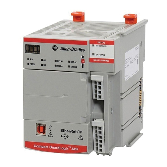
GuardLogix Controller System Chapter 2 Compact GuardLogix 5380 The Compact GuardLogix 5380 controller is a SIL 2 capable controller that performs standard and safety control functions for safety-related functions in Controller Hardware the Compact GuardLogix control system. Controller Cat. No. Compact GuardLogix 5380 controller 5069-L306ERMS2, 5069-L306ERS2, 5069-L310ERMS2, 5069-L310ERS2, 5069-L320ERMS2, 5069-L320ERS2, 5069-L320ERS2K, 5069-L320ERMS2K,... -
Page 18: Power Supply
This section provides examples of network communication configurations. EtherNet/IP Network The GuardLogix 5580 controller connects directly to an EtherNet/IP network through the onboard Ethernet port and supports 10/100/1000 MBps network speeds. A separate Ethernet communication module is not required, but can be used in the local chassis. - Page 19 GuardLogix Controller System Chapter 2 Figure 3 - GuardLogix 5580 Peer-to-peer Communication Via the EtherNet/IP Network Stratix 5410 Switch 10/100/1000 PoE+ 3 4 5 6 7 8 9 10 11 12 25 26 17 18 19 21 22 23 Disp.
- Page 20 Chapter 2 GuardLogix Controller System Compact GuardLogix 5380 controllers connect directly to the EtherNet/IP network through the onboard Ethernet ports. They also support 10/100/1000 Mbps network speeds. A local Ethernet communication module is not used. Figure 4 - Compact GuardLogix 5380 Peer-to-peer Communication Via the EtherNet/IP Network Stratix 5410 Switch 10/100/1000 PoE+...
-
Page 21: Devicenet Safety Network
Chapter 2 DeviceNet Safety Network DeviceNet bridges let the GuardLogix controller control and exchange safety data with Safety I/O modules on a DeviceNet network. Figure 5 - GuardLogix 5580 Communication Via a DeviceNet Bridge Logix5584ES™ Logix55L8SP™ DC INPUT GuardLogix 5580 Controller... -
Page 22: Programming Overview
Chapter 2 GuardLogix Controller System Programming Overview Use the Studio 5000 Logix Designer application to program GuardLogix safety controllers. Use the Studio 5000 Logix Designer application to define the location, ownership, and configuration of I/O devices and controllers and create, test, and debug program logic. -
Page 23: Typical Safety Functions Of Safety I/O Devices
Chapter Safety I/O for the GuardLogix Control System Topic Page Typical Safety Functions of Safety I/O Devices Reaction Time Safety Considerations for Safety I/O Devices Before you operate a GuardLogix safety system with Safety I/O devices, you must first read, understand, and follow all safety information in the product documentation for those products. -
Page 24: Status Data
Chapter 3 Safety I/O for the GuardLogix Control System Status Data In addition to safety input and output data, Safety I/O devices support status data to monitor device and I/O circuit health. See the product documentation for your device for specific product capabilities. Status Indicators The Safety I/O devices include status indicators. -
Page 25: Safety Considerations For Safety I/O Devices
Safety I/O for the GuardLogix Control System Chapter 3 Safety Considerations for You must commission all devices with a node or IP address and communication rate, if necessary, before their installation on a safety network. Safety I/O Devices Ownership One GuardLogix controller owns each Safety I/O device in a GuardLogix system. -
Page 26: Safety I/O Device Replacement
Chapter 3 Safety I/O for the GuardLogix Control System When using a third-party module, if you connect to a safety I/O device without a configuration signature, you must verify that a valid configuration exists in the safety I/O device. IMPORTANT Rockwell Automation safety I/O modules typically default to using the configuration signature;... - Page 27 For detailed information, see the ‘Replace a Safety I/O Device’ procedure in the user manual for the controller: • ControlLogix 5580 and GuardLogix 5580 Controllers User Manual, publication 1756-UM543 • CompactLogix 5380 and Compact GuardLogix 5380 User Manual,...
- Page 28 ATTENTION: To place a device in the out-of-box condition on a Safety network when the Configure Always feature is enabled, follow the device replacement procedure in the user manual: • ControlLogix 5580 and GuardLogix 5580 Controllers User Manual, publication 1756-UM543 •...
-
Page 29: Unique Node Reference
Chapter CIP Safety and Safety Network Numbers Topic Page Unique Node Reference Safety Network Numbers (SNN) Routable CIP Safety System Considerations for Assigning SNNs How SNNs Get to Safety Devices SNN Formats SNNs for Out-of-box Devices Unique Node Reference CIP Safety control systems are composed of CIP Safety devices that are interconnected via communication networks. -
Page 30: Routable Cip Safety System
Chapter 4 CIP Safety and Safety Network Numbers Routable CIP Safety System The example system in Figure 8 is not interconnected to another CIP Safety system through a larger, plant-wide Ethernet backbone. Therefore, Figure 8 illustrates the extent of a routable CIP Safety system. Figure 8 - Safety System Example Switch Switch... - Page 31 CIP Safety and Safety Network Numbers Chapter 4 You can also choose to map out the entire routable system (perhaps for the entire plant), and manually assign SNN values to each subnet. The Studio 5000 Logix Designer application provides a manual entry method for assigning SNN values to enable this design methodology.
-
Page 32: How Snns Get To Safety Devices
Chapter 4 CIP Safety and Safety Network Numbers Figure 10 - Controller Organizer SNN_4 SNN_1 SNN_5 The configuration profile for each CIP Safety device in the I/O tree includes a parameter for the SNN value that the controller uses when it opens the CIP Safety connection to that device. -
Page 33: Snn Formats
CIP Safety and Safety Network Numbers Chapter 4 SNN Formats SNNs used by the system are 6-byte hexadecimal numbers. SNNs can be set and viewed in one of two formats: • Time-based • Manual Time-based SNN Format and Assignment When the time-based format is selected, the SNN represents a localized date and time. -
Page 34: Manual Snn Format And Assignment
SNN values cannot be repeated. See the following user manuals for information on how to change the SNN: • ControlLogix 5580 and GuardLogix 5580 Controllers User Manual, publication 1756-UM543 • CompactLogix 5380 Controllers User Manual, publication... -
Page 35: Snns For Out-Of-Box Devices
SNN applied before it is added to the CIP Safety network. For detailed information, see the ‘Replace a Safety I/O Device’ procedure in the user manual for the controller: • ControlLogix 5580 and GuardLogix 5580 Controllers User Manual, publication 1756-UM543 • CompactLogix 5380 and Compact GuardLogix 5380 User Manual,... - Page 36 Chapter 4 CIP Safety and Safety Network Numbers Notes: Rockwell Automation Publication 1756-RM012B-EN-P - April 2018...
-
Page 37: Differentiate Between Standard And Safety
I/O devices. • GuardLogix 5580 controllers support both SIL 2 and SIL 3 levels of safety control with the safety task. See SIL Certification on page •... -
Page 38: The Safety Task
Chapter 5 Characteristics of Safety Tags, the Safety Task, and Safety Programs The Safety Task IMPORTANT Only the instructions that are listed in Appendix A page 69 can be used in the safety task. Creation of a GuardLogix project automatically creates one safety task. The safety task has these additional characteristics: •... -
Page 39: Safety Task Execution Details
Characteristics of Safety Tags, the Safety Task, and Safety Programs Chapter 5 Safety Task Execution Details The safety task executes in the same manner as standard periodic tasks, with the following exceptions: • Safety input tags and safety-consumed tags are updated only at the beginning of safety task execution. -
Page 40: Sil 2 And Sil 3 Safety Application Differences
While another machine has multiple safety functions, with at least one risk requiring SIL 3. In that case, a SIL 3 capable controller is required. As discussed in this publication, a SIL 2 GuardLogix 5580 controller requires only the primary controller, and a SIL 3 GuardLogix 5580 controller requires both the primary controller and the safety partner. - Page 41 Characteristics of Safety Tags, the Safety Task, and Safety Programs Chapter 5 From a safety architecture perspective, using single channel means that the hardware fault tolerance (HFT) is zero. When the HFT is zero, there are guidelines that state that faults must be detected and the safety function must be taken to a safe state within the process safety time.
-
Page 42: Use Of Human Machine Interfaces
Chapter 5 Characteristics of Safety Tags, the Safety Task, and Safety Programs A typical SIL 3 wiring diagram is shown in Figure Figure 15 - SIL 3 Wiring IMPORTANT These wiring drawings are examples of possible wiring configurations. Depending on your I/O device and system configuration, other wiring configurations can also be used. -
Page 43: Access To Safety-Related Systems
Characteristics of Safety Tags, the Safety Task, and Safety Programs Chapter 5 Access to Safety-related Systems HMI-related functions consist of two primary activities: reading and writing data. Read Parameters in Safety-related Systems Reading data is unrestricted because reading doesn’t affect the behavior of the safety system. -
Page 44: Safety Programs
Chapter 5 Characteristics of Safety Tags, the Safety Task, and Safety Programs • Sufficiently document all safety-related changes that are made via the HMI, including the following: – Authorization – Impact analysis – Execution – Test information – Revision information •... -
Page 45: Safety Tags
Characteristics of Safety Tags, the Safety Task, and Safety Programs Chapter 5 Safety Tags The GuardLogix control system supports the use of both standard and safety tags in the same project. However, the programming software operationally differentiates standard tags from safety tags. Safety tags have the attributes of standard tags with the addition of mechanisms to provide data integrity at the configured SIL level (SIL 2 or SIL 3). -
Page 46: Standard Tags In Safety Routines (Tag Mapping)
Chapter 5 Characteristics of Safety Tags, the Safety Task, and Safety Programs Standard Tags in Safety Routines (Tag Mapping) Controller-scoped standard tags can be mapped into safety tags, providing you with a mechanism to synchronize standard and safety actions. ATTENTION: When using standard data in a safety routine, you are responsible for providing a more reliable means to make sure that the data is used in an appropriate manner. -
Page 47: Safety Concept Assumptions
Chapter Safety Application Development Topic Page Safety Concept Assumptions Basics of Application Development and Testing Commissioning Lifecycle Download the Safety Application Program Upload the Safety Application Program Store and Load a Project from a Memory Card Force Data Inhibit a Device Online Editing Editing Your Safety Application Safety Concept Assumptions... -
Page 48: Basics Of Application Development And Testing
Chapter 6 Safety Application Development Table 1 - Effect of Controller Modes on Safety Execution Controller Mode Controller Behavior Program • Safety input and output connections are established and maintained: – Safety input tags are updated to reflect safety input values. •... - Page 49 Safety Application Development Chapter 6 The Studio 5000® environment is a suite of tools that are certified as an offline tool according to clause 7.4.4 of IEC 61508-3. As you develop your safety application, consider the following: IMPORTANT • The Studio 5000 Logix Designer application has been certified to clause 7.4.4 of IEC 61508-3 Edition 2 and may be used during the coding lifecycle of GuardLogix-based applications and also as an aide in the module test, integration test, and validation test lifecycle phases.
-
Page 50: Commissioning Lifecycle
Chapter 6 Safety Application Development The flowchart shows the steps that are required for commissioning a Commissioning Lifecycle GuardLogix system. See the links for an explanation of those topics. Figure 17 - Commission the System Specification of the Safety Function on page 51 Create the Project on page 52 Create the Project on page 52... -
Page 51: Specification Of The Safety Function
Safety Application Development Chapter 6 Specification of the Safety Function You must create a specification for your safety function. Use this specification to verify that program logic correctly and fully addresses the functional and safety control requirements of your application. In some applications, the specification can be presented in various formats. -
Page 52: Create The Project
Chapter 6 Safety Application Development Create the Project The logic and instructions that are used in programming the application must be the following: • Easy to understand • Easy to trace • Easy to change • Easy to test Review and test all logic. Keep safety-related logic and standard logic separate. Label the Program Use these labels to identify the application program clearly: •... -
Page 53: Validate The Project
Safety Application Development Chapter 6 You can generate the safety signature if the following conditions are true: • The Studio 5000 Logix Designer application is online with the controller. • The controller is in Program mode. • The controller is safety-unlocked. •... -
Page 54: Confirm The Project
Chapter 6 Safety Application Development Active simulation with sources (field devices) must also be included, as it is the only way to verify that the sensors and actuators in the system are wired correctly. Verify the operation of programmed functions by manipulating sensors and actuators manually. -
Page 55: Safety Assessment
Safety Application Development Chapter 6 5. Move the original project archive file out of its current directory. You can delete this file or store it in an archival location. This step is required because if the Studio 5000 Logix Designer application finds the projectname.ACD in this directory, it correlates it with the controller project and does not perform an actual upload. -
Page 56: Download The Safety Application Program
-unlock the controller. Passwords are optional. For more information about the safety-lock feature, see the user manual for the controller: • ControlLogix 5580 and GuardLogix 5580 Controllers User Manual, publication 1756-UM543 • CompactLogix 5380 and Compact GuardLogix 5380 User Manual,... -
Page 57: Upload The Safety Application Program
Safety Application Development Chapter 6 Upload the Safety If the GuardLogix controller contains a safety signature, the safety signature is uploaded in an online save of the project. As a result, all offline safety tag values Application Program are updated to the snapshot values saved at the moment the signature was generated. -
Page 58: Inhibit A Device
Chapter 6 Safety Application Development Inhibit a Device You cannot inhibit or uninhibit Safety I/O devices or producer controllers if the application program is safety-locked or a safety signature exists. Follow these steps to inhibit a specific safety I/O device. 1. -
Page 59: Editing Your Safety Application
Safety Application Development Chapter 6 Editing Your Safety The following rules apply to changing your safety application program in the Studio 5000 Logix Designer application: Application • Only authorized, specially trained personnel can make program edits. These personnel must use all supervisory methods available, for example, using the controller key switch and software password protections. -
Page 60: Performing Online Edits
Chapter 6 Safety Application Development Performing Online Edits If online edits affect the safety program, you must revalidate all affected elements of the application, as determined by the impact analysis, before you resume operation. Figure 18 on page 61 shows the process for online editing. TIP Limit online edits to minor program modifications such as setpoint changes or minor logic additions, deletions, and modifications. -
Page 61: Rockwell Automation Publication 1756-Rm012B-En-P - April
Safety Application Development Chapter 6 Figure 18 - Online and Offline Edit Process Online Edit Offline Edit Open Project Attach to Controller Make Desired Any Safety Any Safety Modifications to Standard Changes? Changes? Logic Unlock the Controller Institute alternate Make Desired Modifications Test the Application Program protection mechanisms to Standard Logic... - Page 62 Chapter 6 Safety Application Development Notes: Rockwell Automation Publication 1756-RM012B-EN-P - April 2018...
-
Page 63: Status Indicators
Appendix D page 89). Status Indicators For details on status indicator operation, see the user manual for the controller: • ControlLogix 5580 and GuardLogix 5580 Controllers User Manual, publication 1756-UM543 • CompactLogix 5380 and Compact GuardLogix 5380 User Manual, publication 5069-UM001 IMPORTANT Status indicators are not reliable indicators for safety functions. -
Page 64: Input And Output Diagnostics
Chapter 7 Monitor Status and Handle Faults Figure 19 - Data Type Dialog Box The first two bits of the CONNECTION_STATUS data type contain the RunMode and ConnectionFaulted status bits of a device. Table 3 describes the combinations of the RunMode and ConnectionFaulted states. Table 3 - Safety Connection Status RunMode ConnectionFaulted... -
Page 65: I/O Device Connection Status
Monitor Status and Handle Faults Chapter 7 I/O Device Connection Status The CIP Safety protocol allows the recipients of I/O data to determine the status of that data: • The controller detects input connection failures, which sets all input data to the safe state and the associated input status to faulted. •... -
Page 66: Value (Ssv) Instructions
For general information on using GSV and SSV instructions, see the Logix5000 Controllers General Instructions Reference Manual, publication 1756-RM003. Safety Faults Faults in the GuardLogix 5580 and Compact GuardLogix 5380 system can be: • Recoverable controller faults • Nonrecoverable controller faults • Nonrecoverable safety faults in the safety application •... -
Page 67: Recoverable Safety Faults In The Safety Application
Monitor Status and Handle Faults Chapter 7 When the safety task encounters a nonrecoverable safety fault, a standard major recoverable fault is also logged, and the controller proceeds to execute the controller fault handler, if one exists. If the controller fault handler handles this fault, then the standard tasks continue to run, even though the safety task remains faulted. -
Page 68: View Faults
5069-UM001 Fault Codes Table 4 shows the fault codes specific to GuardLogix 5580 and Compact GuardLogix 5380 controllers. The type and code correspond to the type and code that is displayed on the Major Faults tab of the Controller Properties dialog box and in the PROGRAM object, MAJORFAULTRECORD (or MINORFAULTRECORD) attribute. -
Page 69: Safety Instructions
Appendix Safety Instructions ATTENTION: These safety instructions are the only instructions that can be used in the safety tasks in SIL 2 or SIL 3 applications. For the latest information on certified instructions, see our safety certificates and revision release list at http://www.rockwellautomation.com/global/certification/safety.page. - Page 70 Appendix A Safety Instructions Table 6 - Metal-form Safety-application Instructions Mnemonic Name Purpose CBCM Clutch Brake Continuous Mode Used for press applications where continuous operation is desired. CBIM Clutch Brake Inch Mode Used for press applications where minor slide adjustments are required, such as press setup. CBSSM Clutch Brake Single Stoke Mode Used in single-cycle press applications.
- Page 71 (3) The event instruction triggers a scan of the standard task. (4) For special considerations when using the GSV and SSV instructions, see the ControlLogix 5580 and GuardLogix 5580 Controllers User Manual, publication 1756-UM543, or the CompactLogix 5380 and Compact GuardLogix 5380 User Manual, publication 5069-UM001.
- Page 72 The Safety Feedback Interface instruction converts motor velocity and position feedback from a drive module into user scaling units. It also defines an absolute reference position. (1) Motion safety instructions are available when using a GuardLogix 5580 controller, Compact GuardLogix 5380, and Kinetix 5700 ERS4 drives with the Studio 5000 Logix Designer application (V31 or later).
- Page 73 Appendix Create and Use a Safety Add-On Instruction Topic Page Create an Add-On Instruction Test Project Create a Safety Add-On Instruction Generate the Instruction Signature The Safety Instruction Signature SIL 2 or SIL 3 Add-On Instruction Qualification Test Safety Validate Add-On Instructions Create Signature History Entry Export and Import the Safety Add-On Instruction Verify Safety Add-On Instruction Signatures...
-
Page 74: Instruction Create A Safety Add-On Instruction
Appendix B Create and Use a Safety Add-On Instruction Figure 20 - Flowchart for Creating and Using Safety Add-On Instructions To use a Safety Add-On Instruction To Create a Safety Add-On Instruction Create or Open a Project To Modify a Safety Add-On Create an Add-On Instruction Test Project on page 75 Instruction (off-line) Export and Import the Safety Add-On Instruction on page 76... -
Page 75: Create An Add-On Instruction Test Project
Create and Use a Safety Add-On Instruction Appendix B Create an Add-On Instruction You must create a unique test project, specifically to create and test the safety Add-On Instruction. This project must be a separate and dedicated project to Test Project minimize any unexpected influences. -
Page 76: The Safety Instruction Signature
Appendix B Create and Use a Safety Add-On Instruction The Safety Instruction When a sealed safety Add-On Instruction is downloaded for the first time, a safety instruction signature is automatically generated. The safety instruction Signature signature is an ID number that identifies the execution characteristics of the safety Add-On Instruction. -
Page 77: Verify Safety Add-On Instruction Signatures
Create and Use a Safety Add-On Instruction Appendix B Verify Safety Add-On After you download the application project that contains the imported safety Add-On Instruction, you must compare the instruction signature value, the Instruction Signatures date and time stamp, and the safety instruction signature values with the original values you recorded before you exported the safety Add-On Instruction. - Page 78 Appendix B Create and Use a Safety Add-On Instruction Notes: Rockwell Automation Publication 1756-RM012B-EN-P - April 2018...
-
Page 79: Connection Reaction Time Limit
Appendix Reaction Times Topic Page Connection Reaction Time Limit System Reaction Time Logix System Reaction Time Factors That Affect Logix Reaction-time Components Connection Reaction Time The Connection Reaction Time Limit is the maximum age of safety packets on the associated connection. If the age of the data that is used by the Limit consuming device exceeds the Connection Reaction Time Limit, a connection fault occurs. -
Page 80: Specify The Requested Packet Interval (Rpi)
Appendix C Reaction Times Specify the Requested Packet Interval (RPI) The RPI specifies the period that data updates over a connection. For example, an input module produces data at the RPI that you assign. For safety input connections, you can set the RPI on the Safety tab of the Module Properties dialog box. -
Page 81: System Reaction Time
Reaction Times Appendix C System Reaction Time To determine the system reaction time (see System Reaction Time on page 13 for details) of any control chain, you must add up the reaction times of all of components of the safety chain. System Reaction Time = Sensor Reaction Time + Logix System Reaction Time + Actuator Reaction Time Figure 24 - System Reaction Time... -
Page 82: Logic Chain Using Produced/Consumed Safety Tags
Appendix C Reaction Times The Logix system reaction time for any simple input to logic to output chain consists of these five components: 1. Safety input device reaction time (plus input delay time, if applicable) 2. Safety Input Connection Reaction Time Limit (Read from the Module Properties dialog box in the Studio 5000 Logix Designer application, this value is a multiple of the safety input device connection RPI.) -
Page 83: Factors That Affect Logix Reaction-Time Components
Reaction Times Appendix C 4. Produced/Consumed Safety Connection Reaction Time Limit (Read from the Safety tab of the consumed tag connection.) 5. Safety Task Period plus Safety Task Watchdog time for Controller B 6. Safety Output Connection Reaction Time Limit 7. -
Page 84: Configure Guard I/O Input Module Delay Time Settings
Appendix C Reaction Times Configure Guard I/O Input Module Delay Time Settings To configure input module delay time in the Studio 5000 Logix Designer application, follow these steps. 1. In the configuration tree, right-click your Guard I/O module and choose Properties. 2. - Page 85 Reaction Times Appendix C To view or configure these settings, follow these steps. 1. In the configuration tree, right-click your safety I/O device and choose Properties. 2. Click the Safety tab. 3. Click Advanced to open the Advanced Connection Reaction Time Limit dialog box.
-
Page 86: Configure The Safety Task Period And Watchdog
Appendix C Reaction Times Configure the Safety Task Period and Watchdog The safety task is a periodic timed task. You select the task period, priority, and watchdog time via the Task Properties - Safety Task dialog box in your Studio 5000 Logix Designer project. - Page 87 4. On the Safety tab, click Advanced. 5. You can view or edit the current settings in the Advanced dialog box. See the following for more information. • ControlLogix 5580 and GuardLogix 5580 Controllers User Manual, publication 1756-UM543 • CompactLogix 5380 and Compact GuardLogix 5380 User Manual,...
- Page 88 Appendix C Reaction Times Notes: Rockwell Automation Publication 1756-RM012B-EN-P - April 2018...
- Page 89 Appendix Checklists for GuardLogix Safety Applications Topic Page Checklist for GuardLogix Controller System Checklist for Safety Inputs Checklist for Safety Outputs Checklist to Develop a Safety Application Program The checklists in this appendix are required to plan, program, and start a GuardLogix safety application.
-
Page 90: Checklist For Guardlogix Controller System
Appendix D Checklists for GuardLogix Safety Applications Checklist for GuardLogix Controller System Checklist for GuardLogix System Company Site Safety Function Definition Fulfilled Number System Requirements Comment Are you using only the certified components for your SIL level, with the corresponding firmware release, as listed at http://www.rockwellautomation.com/global/certification/safety.page? Have you calculated the safety response time of the system for each safety function? Does the response time of the system’... -
Page 91: Checklist For Safety Inputs
Checklists for GuardLogix Safety Applications Appendix D Checklist for Safety Inputs For programming or startup, an individual checklist can be completed for every safety input in the system. This method is the only way to make sure that the requirements are fully and clearly implemented. This checklist can also be used as documentation on the connection of external wiring to the application program. -
Page 92: Checklist For Safety Outputs
Appendix D Checklists for GuardLogix Safety Applications Checklist for Safety Outputs For programming or startup, an individual requirement checklist must be completed for every safety output in the system. This method is the only way to make sure that the requirements are fully and clearly implemented. This checklist can also be used as documentation on the connection of external wiring to the application program. -
Page 93: Checklist To Develop A Safety Application Program
Has the review been documented and signed? (1) The Studio 5000 Logix Designer application, version 31 or later, supports GuardLogix 5580 and Compact GuardLogix 5380 controllers. (2) To obtain the latest software and firmware, see the Rockwell Automation Product Compatibility and Download Center (PCDC) support website at http://www.rockwellautomation.com/global/support/pcdc.page. - Page 94 Appendix D Checklists for GuardLogix Safety Applications Notes: Rockwell Automation Publication 1756-RM012B-EN-P - April 2018...
-
Page 95: Useful Life
Appendix GuardLogix Systems Safety Data Topic Page Useful Life Safety Data Product Failure Rates The following examples show probability of a dangerous failure on demand (PFD) and probability of dangerous failure per hour (PFH) values for GuardLogix 1oo1 SIL 2 system or 1oo2 SIL 3 system. For safety data that includes PFD and PFH values for safety I/O modules, see the manuals for those devices. -
Page 96: Product Failure Rates
Appendix E GuardLogix Systems Safety Data Product Failure Rates The data in the following tables applies to mission times up to and including 20 years. Table 12 - Safety Parameters GuardLogix 5580 Compact Controllers and GuardLogix 5580 GuardLogix 5380 (2) (3) -
Page 97: De-Energize To Trip System
Appendix Studio 5000 Logix Designer Application, Version 31 or Later, Safety-application Instructions Topic Page De-energize to Trip System Use Connection Status Data to Initiate a Fault Programmatically IMPORTANT We recommend use of general safety-application instructions (Table 5 on page 69) rather than the instructions detailed in this appendix. De-energize to Trip System All safety input values that are associated with a particular connection are set to safe state when a CIP Safety connection fault condition is detected. - Page 98 Appendix F Studio 5000 Logix Designer Application, Version 31 or Later, Safety-application Instructions Figure 27 - Input Fault Latch and Reset Flowchart Start Does this safety function require operator intervention after a safety input failure? Are the inputs used to drive safety application instructions? Make sure that you select Manual Reset for the safety...
- Page 99 Studio 5000 Logix Designer Application, Version 31 or Later, Safety-application Instructions Appendix F Figure 28 - Ladder Diagram Example 1 Node 30 is an 8-point input/8-point output combination module. Node 31 is a 12-point input module. If the input status is not OK, then latch the inputs faulted indication. Node30:I.InputStatus Node30InputsFaulted Node31:I.CombinedStatus...
- Page 100 Appendix F Studio 5000 Logix Designer Application, Version 31 or Later, Safety-application Instructions Figure 29 - Ladder Diagram Example 2 Node 30 is an 8-point input/8-point output combination module. Node 31 is a 12-point input module. If the input status is not OK, then latch the inputs faulted indication. Node30:I.InputStatus Node30InputsFaulted Node31:I.CombinedStatus...
- Page 101 Studio 5000 Logix Designer Application, Version 31 or Later, Safety-application Instructions Appendix F Figure 30 - Output Fault Latch and Reset Flowchart Start Does this safety function require operator intervention after a safety output failure? Write logic to latch output failure. Is output fault information required for (Example Rung 0) diagnostic purposes?
- Page 102 Appendix F Studio 5000 Logix Designer Application, Version 31 or Later, Safety-application Instructions Notes: Rockwell Automation Publication 1756-RM012B-EN-P - April 2018...
-
Page 103: Glossary
Glossary The following terms and abbreviations are used throughout this manual. For definitions of terms that are not listed here, see the Allen-Bradley Industrial Automation Glossary, publication AG-7.1. 1oo1 (one-out-of-one) Identifies the programmable electronic controller architecture. 1oo1 is a single-channel system. - Page 104 Glossary instruction signature The instruction signature consists of an ID number and date/time stamp that identifies the contents of the Add-On Instruction definition at a given point in time. lambda (λ) Designation of a failure rate. MT (mission time) The length of time over which the device maintains the stated PFD, PFH, and λ...
- Page 105 Glossary Probability of a dangerous failure on The average probability of a dangerous failure on demand. demand (PFD) Probability of dangerous failure per The average frequency of a dangerous failure per hour. hour (PFH) recoverable fault A fault, which when properly handled by implementing the fault handling mechanisms that are provided by the controller, does not force user logic execution to be ended.
- Page 106 Glossary safety program A safety program has all attributes of a standard program, except that it can be scheduled only in a safety task. The safety program consists of zero or more safety routines. It cannot contain standard routines or standard tags. safety protocol A network communication method that is designed and certified for transport of data with high integrity.
- Page 107 Glossary symbolic addressing A method of addressing that provides an ASCII interpretation of the tag name. system reaction time The worst case time from a safety-related event as input to the system or as a fault within the system, until the time that the system is in the safe state. System reaction time includes sensor and actuator Reaction Times, Input and Output Reaction Times (including network connection delays), and the Controller Reaction Time.
- Page 108 Glossary Notes: Rockwell Automation Publication 1756-RM012B-EN-P - April 2018...
-
Page 109: Index
Index concept safety integrity level (SIL) 9 access configuration signature 25 safety-related system 43 confirm Add-On Instruction project 54 create test project 75 connection reaction time limit 79 export and import 76 connection status 64 flowchart 74 I/O device 65 instruction signature 75 connection status data qualification test... -
Page 110: Rockwell Automation Publication 1756-Rm012B-En-P - April
Index checklist 90 power supply 16 edit primary controller 16 offline 59 safety application checklist 89 online 58 safety partner 16 process 61 system safety data 95 emergency shutdown system 9 GuardLogix controller EtherNet/IP network 18 system 15 European norm. definition 103 example human machine interface... - Page 111 I/O 40 monitor definition 104 power supply system status 63 Compact GuardLogix 18 Compact GuardLogix 5380 systems 18 GuardLogix 16 GuardLogix 5580 systems 16 network primary controller 15 communication 18 definition 104 DeviceNet safety 21 GuardLogix 16 EtherNet/IP 18...
- Page 112 Index safety I/O configuration signature 25 reaction time 79 device replacement 26 calculate for system 81 GuardLogix control system 23 input 24 module 40 Logix system 81 safety function 23 output 24 safety instruction signature 76 safety task 13 definition 105 system 13 safety integrity level reaction time limit...
- Page 113 Index safety-related system test access 43 application program 52 read parameters 43 modification impact 60 set system variable (SSV) test project instruction 66 create signature 25 Add-On Instruction 75 testing signature history 76 application 48 time concept 9 reaction 79 SIL 2 time-based safety application 40...
- Page 114 Index Rockwell Automation Publication 1756-RM012B-EN-P - April 2018...
- Page 116 Rockwell Automation maintains current product environmental information on its website at http://www.rockwellautomation.com/rockwellautomation/about-us/sustainability-ethics/product-environmental-compliance.page. Allen-Bradley, ArmorBlock, Compact 5000, CompactBlock, CompactLogix, ControlLogix, Guard I/O, GuardLogix, Kinetix, Logix5000, POINT Guard I/O, POINT I/O, PowerFlex, Rockwell Automation, Rockwell Software, RSLogix 5000, Stratix, Studio 5000, and Studio 5000 Logix Designer are trademarks belonging to Rockwell Automation, Inc.