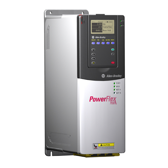
Allen-Bradley PowerFlex 700 Quick Start Manual
Adjustable frequency ac drive
Hide thumbs
Also See for PowerFlex 700:
- Quick start manual ,
- User manual (198 pages) ,
- Installation instructions manual (96 pages)
Table of Contents
PowerFlex 700 Adjustable
Frequency AC Drive
When reading this document, look for this symbol "
you through the 6 BASIC STEPS needed to install, start-up and
program the PowerFlex 700. The information provided Does Not
replace the User Manual and is intended for qualified drive service
personnel only. For detailed PowerFlex 700 information including
application considerations and related precautions refer to the following:
Title
PowerFlex 700 User Manual 20B-UM001x
PowerFlex Reference Manual PFLEX-RM001x
Step 1
Read the General Precautions
ATTENTION: This drive contains ESD (Electrostatic Discharge)
sensitive parts and assemblies. Static control precautions are required
!
when installing, testing, servicing or repairing this assembly.
Component damage may result if ESD control procedures are not
followed. If you are not familiar with static control procedures,
reference A-B publication 8000-4.5.2, "Guarding Against Electrostatic
Damage" or any other applicable ESD protection handbook.
ATTENTION: An incorrectly applied or installed drive can result in
component damage or a reduction in product life. Wiring or application
!
errors, such as, undersizing the motor, incorrect or inadequate AC
supply, or excessive ambient temperatures may result in malfunction of
the system.
ATTENTION: Only qualified personnel familiar with adjustable
frequency AC drives and associated machinery should plan or
!
implement the installation, start-up and subsequent maintenance of the
system. Failure to comply may result in personal injury and/or
equipment damage.
ATTENTION: To avoid an electric shock hazard, verify that the
voltage on the bus capacitors has discharged before performing any
!
work on the drive. Measure the DC bus voltage at the +DC & –DC
terminals of the Power Terminal Block (refer to the User Manual for
location). The voltage must be zero.
Publication
Available . . .
on the CD supplied with the drive
or at
Quick Start
Step x
" to guide
www.ab.com/manuals/dr
Table of Contents

Related Manuals for Allen-Bradley PowerFlex 700


Summary of Contents for Allen-Bradley PowerFlex 700
- Page 1 ” to guide you through the 6 BASIC STEPS needed to install, start-up and program the PowerFlex 700. The information provided Does Not replace the User Manual and is intended for qualified drive service personnel only. For detailed PowerFlex 700 information including...
- Page 2 AC line to the drive. An auxiliary braking method may be required. ATTENTION: If using Output Contactors, refer to the “Output Contactor Precaution” statement on page 1-12 of the PowerFlex 700 User Manual.
-
Page 3: Emc Instructions
PowerFlex 700 Adjustable Frequency AC Drive Quick Start EMC Instructions CE Conformity Conformity with the Low Voltage (LV) Directive and Electromagnetic Compatibility (EMC) Directive has been demonstrated using harmonized European Norm (EN) standards published in the Official Journal of the European Communities. PowerFlex Drives comply with the EN standards listed below when installed according to the User and Reference Manual. -
Page 4: Essential Requirements For Ce Compliance
101.6 mm 101.6 mm (4.0 in.) (4.0 in.) (4.0 in.) (4.0 in.) detailed dimension information. Operating Temperatures PowerFlex 700 drives are designed to operate at 0° to 40° C ambient. To operate in installations between 41° and 50° C, see Table... - Page 5 Rotate the plate out from the back plate. Important: Removing the adhesive label from the drive changes the NEMA enclosure rating from Type 1 to Open type. Dimensions Figure 1 PowerFlex 700 Frames 0-3 (0 Frame Shown) 15.0 (0.59) see below 5.8 (0.23) dia.
- Page 6 PowerFlex 700 Adjustable Frequency AC Drive Quick Start Figure 2 PowerFlex 700 Frame 5 6.5 (0.26) 15.0 (0.59) 259.1 (10.20) Detail 37.6 (1.48) CAUTION HOT surfaces can cause severe burns Lifting Holes - 4 Places 6.5 (0.26) 12.7 (1.37) Dia.
- Page 7 PowerFlex 700 Adjustable Frequency AC Drive Quick Start Figure 3 Bottom View Dimensions Frame 0 Frame 1 96.0 (3.78) 108.5 (4.27) 87.5 (3.44) 75.0 (2.95) 55.0 (2.17) 67.5 (2.66) 35.0 (1.38) 47.5 (1.87) 22.2 (0.87) Dia. 22.2 (0.87) Dia. – 4 Places 3 Places 28.6 (1.13) Dia.
- Page 8 PowerFlex 700 Adjustable Frequency AC Drive Quick Start Figure 3 PowerFlex 700 Bottom View Dimensions (continued) Frame 3 – 50 HP, 480V (37 kW, 400V) Frame 3 – All Drives Normal Duty Drive except 50 HP, 480V (37 kW, 400V) 34.9 (1.37) Dia.
- Page 9 See Table D. For further information on acceptable and unacceptable cable types, refer to “Power Wiring” in the PowerFlex 700 User Manual. Table D Recommended Shielded Cable Type Wire Type(s)
-
Page 10: Frame Description
PowerFlex 700 Adjustable Frequency AC Drive Quick Start Table E Power Terminal Block Specifications Wire Size Range Torque Name Frame Description Maximum Minimum Maximum Recommended Power Terminal 0 & 1 Input power and 4.0 mm 0.5 mm 1.7 N-m 0.8 N-m... -
Page 11: Control Wiring
PowerFlex 700 Adjustable Frequency AC Drive Quick Start Step 4 Control Wiring • Always use copper wire. • Wire with an insulation rating of 600V or greater is recommended. • Control and signal wires should be separated from power wires by at least 0.3 meters (1 foot). -
Page 12: I/O Terminal Blocks
PowerFlex 700 Adjustable Frequency AC Drive Quick Start I/O Terminal Blocks Figure 4 Vector Control Option I/O Terminal Designations Vector Control Option No. Signal Description Analog In 1 (–) Isolated , bipolar, differential, 320 - ±10V/4-20mA, 11 bit & sign, 88k Analog In 1 (+) ohm input impedance. - Page 13 PowerFlex 700 Adjustable Frequency AC Drive Quick Start Encoder Terminal Block (Vector Control Option Only) Figure 5 Encoder Terminal Designations Description (refer to User Manual for encoder specifications) See “Detail” in +12V DC Power Internal power source User Manual 250 mA.
- Page 14 PowerFlex 700 Adjustable Frequency AC Drive Quick Start Figure 7 Standard Control Option I/O Terminal Designations Standard Control Option No. Signal Description Anlg Volts In 1 (–) Isolated , bipolar, differential, 320 - ±10V, 11 bit & sign, 88k ohm input Anlg Volts In 1 (+) impedance.
-
Page 15: I/O Wiring Examples
PowerFlex 700 Adjustable Frequency AC Drive Quick Start I/O Wiring Examples Input/Output Connection Example Required Parameter Changes Potentiometer • Adjust Scaling: Unipolar Speed Parameters 91/92 and 325/326 Reference • View Results: 10k Ohm Pot. Parameter 002 Recommended (2k Ohm Minimum) Joystick Bipolar •... - Page 16 PowerFlex 700 Adjustable Frequency AC Drive Quick Start I/O Wiring Examples (continued) Input/Output Connection Example Required Parameter Changes 2-Wire Control • Disable Digital Input:#1: Non-Reversing Parameter 361 = “0, Unused” 24V DC internal • Set Digital Input #2: supply Parameter 362 = “7, Run”...
-
Page 17: Start-Up Checklist
PowerFlex 700 Adjustable Frequency AC Drive Quick Start Step 5 Start-Up Check List ❏ 1. Verify supply voltage. PORT NET A NET B ❏ 2. Check power wiring. U V W PE ❏ 3. Check control wiring. ❏ 4. Apply AC power and control voltages to the drive. -
Page 18: Status Indicators
PowerFlex 700 Adjustable Frequency AC Drive Quick Start Status Indicators Name Color State Description Green Steady Illuminates when power is applied to the drive. POWER Green Flashing Drive ready, but not running and no faults are present. Steady Drive running, no faults are present. -
Page 19: Frequently Used Parameters
PowerFlex 700 Adjustable Frequency AC Drive Quick Start Important Notes about Parameters = Stop drive before changing this parameter. = 32 bit parameter in the Standard Control option. All parameters in the Vector Control option are 32 bit. = Parameter only displayed when [Motor Cntl Sel] is set to “4.”... - Page 20 PowerFlex 700 Adjustable Frequency AC Drive Quick Start Parameter Name & Description Values 061 [Autotune] Default: “Calculate” Provides a manual or automatic method Options: “Ready” for setting [IR Voltage Drop], [Flux “Static Tune” Current Ref] and [Ixo Voltage Drop]. “Rotate Tune”...
- Page 21 PowerFlex 700 Adjustable Frequency AC Drive Quick Start Parameter Name & Description Values [Speed Units] Default: “Hz” Vector Selects the units to be used for all speed Options: “Hz” related parameters. Options 0 & 1 “RPM” indicate status only. Options 3 & 4 will “Convert Hz”...
- Page 22 PowerFlex 700 Adjustable Frequency AC Drive Quick Start Parameter Name & Description Values 091 [Speed Ref A Hi] Default: [Maximum Speed] Scales the upper value of the [Speed Ref Min/Max: –/+[Maximum Speed] A Sel] selection when the source is an Units: 0.1 Hz...
- Page 23 PowerFlex 700 Adjustable Frequency AC Drive Quick Start Parameter Name & Description Values 151 [PWM Frequency] Default: 4 kHz Sets the carrier frequency for the PWM Min/Max: 2/10 kHz output. Drive derating may occur at Units: 1 kHz higher carrier frequencies. For derating information, refer to the PowerFlex Reference Manual.
- Page 24 PowerFlex 700 Adjustable Frequency AC Drive Quick Start Parameter Name & Description Values 320 [Anlg In Config] Selects the mode for the analog inputs. 1 =Current 0 =Voltage x =Reserved Bit # Factory Default Bit Values [Analog In 1 Hi] Default: 10.000 Volt...
- Page 25 PowerFlex 700 Adjustable Frequency AC Drive Quick Start Parameter Name & Description Values [Digital In1 Sel] Default: “Stop – CF” [Digital In2 Sel] Default: “Start” [Digital In3 Sel] Default: “Auto/ Manual” [Digital In4 Sel] Default: “Speed Sel 1” [Digital In5 Sel] Default: “Speed Sel 2”...
-
Page 26: Troubleshooting - Abbreviated Fault & Alarm Listing
PowerFlex 700 Adjustable Frequency AC Drive Quick Start Troubleshooting – Abbreviated Fault & Alarm Listing For a complete listing of Faults and Alarms, refer to the PowerFlex 700 User Manual. Fault Description Action ➀ Auxiliary Input Auxiliary input interlock is open. -
Page 27: Manually Clearing Faults
PowerFlex 700 Adjustable Frequency AC Drive Quick Start Alarm Description ➁ Dig In Digital input functions are in conflict. Combinations marked with a “ ” will ConflictA cause an alarm. * Jog 1 and Jog 2 with Vector Control Option... - Page 28 Rockwell Automation, 777 East Wisconsin Avenue, Suite 1400, Milwaukee, WI, 53202-5302 USA, Tel: (1) 414.212.5200, Fax: (1) 414.212.5201 Headquarters for Allen-Bradley Products, Rockwell Software Products and Global Manufacturing Solutions Americas: Rockwell Automation, 1201 South Second Street, Milwaukee, WI 53204-2496 USA, Tel: (1) 414.382.2000, Fax: (1) 414.382.4444...