Table of Contents
Table of Contents

Related Manuals for Allen-Bradley PowerFlex 753


Summary of Contents for Allen-Bradley PowerFlex 753
- Page 1 Quick Start PowerFlex 750-Series AC Drives...
-
Page 2: Important User Information
Arc Flash. Arc Flash will cause severe injury or death. Wear proper Personal Protective Equipment (PPE). Follow ALL Regulatory requirements for safe work practices and for Personal Protective Equipment (PPE). Allen-Bradley, PowerFlex, Rockwell Software, and Rockwell Automation are trademarks of Rockwell Automation, Inc. Trademarks not belonging to Rockwell Automation are property of their respective companies. -
Page 3: Table Of Contents
Table of Contents Important User Information ........2 Introduction Who Should Use This Manual . - Page 4 Table of Contents Dynamic Brake Resistor......... . . 66 Acceleration and Deceleration Time .
-
Page 5: Introduction
Introduction This Quick Start publication is designed to guide you through the 6 BASIC STEPS that are required to start up your PowerFlex 750-Series AC drive for the first time for simple applications. Who Should Use This Manual This manual is intended for qualified personnel. •... -
Page 6: For More Information
Introduction For More Information The following table lists publications that provide general drive-related information. Resource Description PowerFlex 750-Series AC Drives Technical Data, Provides detailed information on: publication 750-TD001 • Drive specifications • Option specifications • Fuse and circuit breaker ratings PowerFlex 750-Series AC Drives Installation Instructions, Provides detailed information on: publication... -
Page 7: Step 1: Gather Required Information
Step 1: Gather Required Information Step 1: Gather Required Information When you apply power to your drive for the first time, you need to enter specific information about your application. You need to enter motor nameplate data and set up your I/O. Step 1: Gather Required Information helps you to verify that you have the needed information prior to drive powerup. -
Page 8: Step 2: Validate The Drive Installation
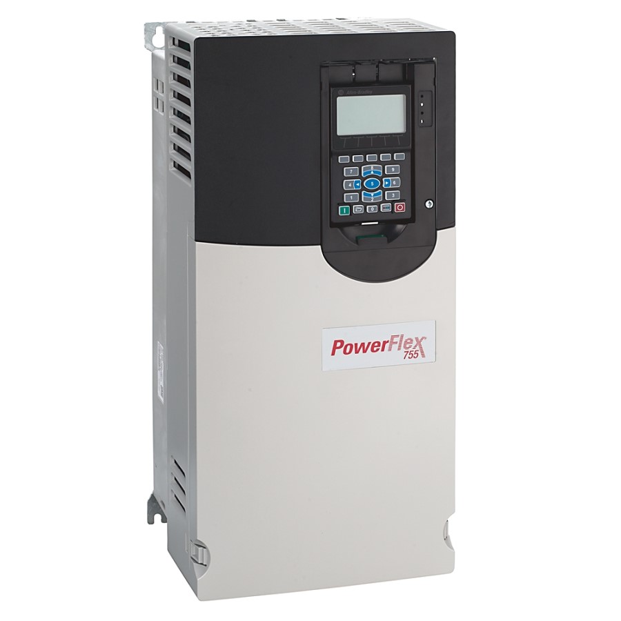
Identify Which Drive You Have There are two types of PowerFlex 750-Series drives, the PowerFlex 753 and the PowerFlex 755. There are some important differences between the drives that need to be considered in subsequent steps. If you don’t know how to determine what... -
Page 9: Verify Power Jumper Configuration
(such as push buttons and potentiometers) are connected to the drive. 1. The drive’s main control board. • Terminal block TB1 on a PowerFlex 753 • Embedded EtherNet/IP port on a PowerFlex 755 • Terminal block TB1 on a PowerFlex 755 Di0 2. -
Page 10: Where Are Signal Sources Connected
Item Description Terminal block TB1, PowerFlex 753 drives. Embedded EtherNet/IP, PowerFlex 755 drives. Expansion I/O module, PowerFlex 753 and 755 drives. (Port 4 installation shown.) Communication network module, PowerFlex 753 drives. (Port 6 installation shown.) Terminal block TB1 on PowerFlex 755 drive is located behind the Ethernet port. - Page 11 Yes: Port No. Yes: Port No. Yes: Port No. Yes: Port No. Are signal sources connected to a communication network module installed in your PowerFlex 753 drive? If yes, note the module’s port number. Drive 1: Drive 2: Drive 3:...
-
Page 12: Power The Drive
20G...B4P2 Exit Startup ABORT ABORT ENTER PAR# TEXT ENTER PAR# TEXT Startup Screen Main Startup Screen PowerFlex 753 Main Powerup Screen PowerFlex 755 Main Powerup Screen 5. Proceed to Drive Setup on page Rockwell Automation Publication 750-QS001A-EN-P - March 2015... -
Page 13: Drive Setup
4.2A 20F...B4P2 ENTER ENTER PAR# TEXT PowerFlex 753 Powerup Screen Parameter Screen Parameter Screen Keypad 2. Use the numeric value from the Motor Nameplate data gather in Step 1: Gather Required Information under Record Motor Nameplate Data on page 7 to verify the value on the screen. - Page 14 Step 3: Power Up, Configure the Drive, and Spin the Motor Shaft • Parameter 29 [Mtr NP Pwr Units] For parameter 29, choose the unit of measurement is based on the actual nameplate. If the nameplate is in HP (default unit), continue to parameter 30 [Motor NP Power]. If your nameplate value is in kW, change the default power units from HP to kW.
- Page 15 Step 3: Power Up, Configure the Drive, and Spin the Motor Shaft Autotune 1. Access parameter 70 [Autotune]. • Press the PAR# soft key. • Enter 70. • Press the ENTER soft key. 2. Press the EDIT soft key and use the soft keys to select “Static Tune 2.”...
- Page 16 Step 3: Power Up, Configure the Drive, and Spin the Motor Shaft Direction Test ATTENTION: This procedure causes movement of the motor shaft and of any connected equipment. To guard against personal injury or damage to equipment, ensure that all guards are properly installed to help protect against contact with rotating parts. 1.
-
Page 17: Step 4: Set Up Speed Reference And Start/Stop
Drive Device Ports on page 33 for more information.) page 38 User Adjustable at Drive Connections on PowerFlex 753 Main Control Board (Port 0) page 41 0…20 mA Analog Input - Unipolar Speed Reference page 42 0…+10V Analog Input - Unipolar Speed Reference... -
Page 18: Step 5: Special Considerations
75 Expansion I/O module connected to TB1 (TO and TC or T1) as appropriate. Relay Output PowerFlex 753 main control board connected to TB2 (R0C and R0NO or page 76 R0NC) as appropriate. Expansion I/O module connected to TB2 (R0C and R0NO or R0NC) as page 76 appropriate. -
Page 19: Step 6: Verify Drive Operation
Step 6: Verify Drive Operation Step 6: Verify Drive Operation Now that you have completed the steps required to start up your drive for the first time, verify and record that each of your drive/motor combinations is operating correctly. Use the information displayed on the HIM, the drive status indicators to the right of the HIM, and the system operation to assist with verifying drive operation. - Page 20 Step 6: Verify Drive Operation Notes: Rockwell Automation Publication 750-QS001A-EN-P - March 2015...
-
Page 21: Reference Section
Reference Section Reference Section These topics are included to provide more detail about the tasks required to start up and configure your drive. Topic Page Determine Drive Type Power Wiring Power Jumpers Identify Option Modules and Compatible Ports Drive Device Ports HIM Overview Resetting Factory Defaults Typical Speed Reference Examples... -
Page 22: Determine Drive Type
20F = PowerFlex 753 20G = PowerFlex 755 3. Look at the main control board that is installed in the drive. PowerFlex 753 has a 14-point I/O terminal block. PowerFlex 755 has three EtherNet/IP address selectors. Rockwell Automation Publication 750-QS001A-EN-P - March 2015... -
Page 23: Power Wiring
Reference Section Power Wiring Wall Mount Frames 1…3 Power Terminal Block and Termination Point Locations Wall Mount Frame 2 Wall Mount Frame 1 Wall Mount Frame 3 Name Description Power Terminal Block R/L1, S/L2, T/L3, BR1, BR2, +DC, -DC, U/T1, V/T2, W/T3 PE Grounding Studs Terminating point to chassis ground for incoming AC line and motor shields. - Page 24 Reference Section Wall Mount Frames 4…5 Power Terminal Block and Termination Point Locations Wall Mount Frame 4 Wall Mount Frame 5 Name Description Power Terminal Block R/L1, S/L2, T/L3, BR1, BR2, +DC, -DC, U/T1, V/T2, W/T3 PE Grounding Studs Terminating point to chassis ground for incoming AC line and motor shields.
- Page 25 Reference Section Wall Mount Frames 6 and 7 Power Terminal and Termination Point Locations Wall Mount Frame 6 Wall Mount Frame 7 400/480V drives shown. Name Description Power Terminals R/L1, S/L2, T/L3, U/T1, V/T2, W/T3 PE Grounding Studs Terminating point to chassis ground for incoming AC line and motor shield.
- Page 26 Reference Section Floor Mount Frames 8 and Larger Bus Bar Locations, AC Input Drives Floor Mount Frame 8 R / L1 S / L2 T / L3 DC– U / T1 V / T2 W / T3 Name Description Power Bus R/L1, S/L2, T/L3 (Drive only.) DC Bus DC+, DC- (The DC Bus is included with frame 9 and 10 drives.
-
Page 27: Power Jumpers
Reference Section Power Jumpers PowerFlex 750-Series drives, frames 1…7, leave the factory with jumpers PE-A and PE-B in one of two possible configurations. IMPORTANT PowerFlex 750-Series drives, frames 8…10, leave the factory with jumpers PE-A1, PE-A2, and PE-B in one of two possible configurations. - Page 28 Reference Section Power Jumper Locations Wall/flange mount frames 1, 6, and 7 and floor mount frames 8…10 use jumper wires to complete an electrical connection when installed. Wall/flange mount frames 2…5 use jumper screws to complete an electrical connection when installed. Table 1 - Power Jumper Locations for Frames 1…10 Drive Jumper Locations...
- Page 29 Reference Section Table 1 - Power Jumper Locations for Frames 1…10 (Continued) Drive Jumper Locations Frame 6 Wire Connectors Connected Disconnected • Torque: 1.36 N•m (12.0 lb•in) • Tools: 7 mm hex socket and T20 Hexalobular Common Mode PE-B PE-B Frame 7 Disconnected Connected...
- Page 30 Reference Section Table 1 - Power Jumper Locations for Frames 1…10 (Continued) Drive Jumper Locations Frames 8…10 PE-A1 Wire Connector Connected Disconnected • Torque: 1.8 N•m (16.0 lb•in) • Tool: T20 Hexalobular PE-A2 Plug-type Connector Rockwell Automation Publication 750-QS001A-EN-P - March 2015...
- Page 31 Reference Section Table 1 - Power Jumper Locations for Frames 1…10 (Continued) Drive Jumper Locations Frames 8…10 AC Input Drive Shown PE-B Plug-type Connector • Tray Torque: 1.86 N•m (16.0 lb•in) • Tool: T20 Hexalobular Connected Disconnected Rockwell Automation Publication 750-QS001A-EN-P - March 2015...
-
Page 32: Identify Option Modules And Compatible Ports
20-750-DENC-1 20-750-2262C-2R 20-750-1132C-2R 20-750-UFB-1 20-750-S1 20-750-2263C-1R2T 20-750-1133C-1R2T 20-750-2262D-2R 20-750-1132D-2R 20-750-ATEX PowerFlex 753 Drives PowerFlex 755 Drives Frame 1 Ports Frame 2…7 Ports Frame 1 Ports Frame 2…10 Ports Option Module Cat. No. 20-750- 2262C-2R, 2263C-1R2T, 2262D-2R 1132C-2R, 1133C-1R2T, 1132D-2R 1132C-2R, 1133C-1R2T, 1132D-2R... -
Page 33: Drive Device Ports
Reference Section Drive Device Ports Connectors, embedded devices, and installed option modules such as I/O, communication adapters, and DeviceLogix, have unique port number assignments. Connectors and embedded devices have fixed port numbers that cannot be changed. Option modules are assigned a port number when installed. The 750-Series drive uses the term ‘Port’... -
Page 34: Him Overview
Reference Section HIM Overview See the PowerFlex 20-HIM-A6 and 20-HIM-C6S HIM (Human Interface Module) User Manual, publication 20HIM-UM001 for more information on the HIM. The keypad consists of soft keys, navigation and number keys, and single-function keys, which are described in their respective subsections that follow. - Page 35 Reference Section Single-function Keys There are four single-function keys, which are highlighted below and listed in the following table. Each single-function key always performs only its dedicated function. Table 4 - Single-function Keys Single-function Key Name Function Start Starts the drive. Folders Accesses folders for parameters, diagnostics, memory functions, preferences, and other tasks.
- Page 36 Reference Section Table 5 - Soft Key Label Explanation (Continued) Soft Key Label Name Function Clear • Deletes an entire text string. • Displays the Select Action pop-up box used to clear the selected fault, alarm or event, or the entire fault, alarm or event queue.
-
Page 37: Resetting Factory Defaults
Reference Section Resetting Factory Defaults 1. Access the Status screen. Stopped AUTO 0.000 Hz Host Drive 240V 4.2A 20G...D014 PAR# TEXT Status Screen 2. Use the key to scroll to the port of the device whose parameters you want to set to factory defaults (for example, Port 00 for the host drive or the respective port number for one of the drive’s connected peripherals). -
Page 38: Typical Speed Reference Examples
Reference Section Typical Speed Reference Examples User Adjustable at Drive The Control screen (shown below) is used to directly control the drive. It displays vertical bar graphs of the drive’s Speed Reference and Feedback values, and a Key Function Map that corresponds to the navigation/number keys for drive control. Press the (Controls) key to display the Control screen. - Page 39 Reference Section Table 8 - Control Screen Navigation/Number Keys Label Function Jogs the host drive. Decreases the speed reference for the host drive. HELP Displays Rockwell Automation Drives Technical Support direct phone number, website address, and email address. Sets the direction to reverse for the host drive. EDIT REF Enables direct data entry of the speed reference for the host drive.
- Page 40 Reference Section Connections on PowerFlex 753 Main Control Board Terminal block TB1 and the input mode jumpers are mounted directly on the main control board. SK-R1-MCB1-PF753 Table 10 - 753 Main Control Board Details No. Name Description Jumper J4 Input Mode Analog input mode jumper.
- Page 41 Reference Section Table 12 - TB1 Terminal Designations Terminal Name Description Related Param Ao0– Analog Out 0 (–) Bipolar, ±10V , 11 bit & sign, 2 k ohm minimum load. Ao0+ Analog Out 0 (+) 4-20 mA , 11 bit & sign, 400 ohm maximum load.
- Page 42 Reference Section Table 14 - 0…+10V Analog Input - Unipolar Speed Reference Set Direction Mode Port 0: P308 [Direction Mode] = 0 “Unipolar” Common Ai0– Ai0+ Set Selection Port 0: P545 [Spd Ref A Sel] = Port 0: P260 [Anlg In0 Value] 753 Main Control Board TB1 Adjust Scaling Port 0: P261 [Anlg In0 Hi] = 10 Volt...
- Page 43 Reference Section Table 17 - 3-Wire Control on PF753 Main Control Board Internal Supply Set Selection Port 0: P158 [DI Stop] = Port 0: P220 [Digital In Sts], bit 1 = Digital In 1 Port 0: P161 [DI Start] = Port 0: P220 [Digital In Sts], bit 2 = Digital In 2 24VC +24V Stop...
- Page 44 Reference Section Connections on 11-Series Expansion I/O Module Terminal block TB1 and the input mode jumpers are mounted on the option module installed in the drive. 11-Series I/O Module Table 18 - Analog Input Mode Jumpers Voltage Mode Current Mode Table 19 - TB1 Terminal Designations Terminal Name Description...
- Page 45 Reference Section Table 20 - 0…20 mA Analog Input - Unipolar Speed Reference Set Direction Mode Port 0: P308 [Direction Mode] = 0 “Unipolar” Common Ai0– Ai0+ Set Selection Port 0: P545 [Spd Ref A Sel] = Port 4 (or port where your 11-Series I/O Module is installed), See page 10: P50 [Anlg In0 Value] 11-Series I/O Module TB1...
- Page 46 Reference Section Table 23 - 2-Wire Control on 11-Series I/O Module Non-Reversing - Internal Supply Set Direction Mode Port 0: P308 [Direction Mode] = 2 “Rev Disable” Stop-Run Set Selection Di0P Port 0: P163 [DI Run] = Port 4 (or port where your 11-Series I/O Module is installed), See page 10: P1 [Dig In Sts], bit 0 = Input 0 11-Series I/O Module TB1...
- Page 47 Reference Section Table 24 - 3-Wire Control on 11-Series I/O Module Internal Supply Set Selection Port 0: P158 [DI Stop] = Port 4 (or port where your 11-Series I/O Module is installed), See page 10: P1 [Dig In Sts], bit 0 = Input 0 Stop Port 0: P161 [DI Start] = Port 4 (or port where your 11-Series I/O Module is installed), See page...
- Page 48 Reference Section Connections on 22-Series Expansion I/O Module Terminal block TB1 and the input mode jumpers are mounted on the option module installed in the drive. 22-Series I/O Module Table 25 - Input Mode Jumpers Jumper Voltage Mode Current Mode Position Table 26 - TB1 Terminal Designations Terminal Name...
- Page 49 Reference Section Table 27 - 0…20 mA Analog Input - Unipolar Speed Reference at Terminals Ai0± Set Direction Mode Port 0: P308 [Direction Mode] = 0 “Unipolar” Common Ai0– Ai0+ Set Selection Port 0: P545 [Spd Ref A Sel] = Port 4 (or port where your 22-Series I/O Module is installed), See page 10: P50 [Anlg In0 Value] 22-Series I/O Module TB1...
- Page 50 Reference Section Table 30 - 0…20 mA Analog Input - Unipolar Speed Reference at Terminals Ai1± Set Direction Mode Port 0: P308 [Direction Mode] = 0 “Unipolar” Common Ai1– Ai1+ Set Selection Port 0: P545 [Spd Ref A Sel] = Port 4 (or port where your 22-Series I/O Module is installed), See page 10: P60 [Anlg In1 Value] 22-Series I/O Module TB1...
- Page 51 Reference Section Table 33 - 2-Wire Control on 22-Series I/O Module Non-Reversing - Internal Supply Set Direction Mode Port 0: P308 [Direction Mode] = 2 “Rev Disable” Stop-Run 24VC Set Selection +24V Di C Port 0: P163 [DI Run] = Port 4 (or port where your 22-Series I/O Module is installed), See page 10: P1 [Dig In Sts], bit 0 = Input 0 Di 0...
-
Page 52: Ethernet/Ip Communication
Reference Section EtherNet/IP Communication IMPORTANT This section assumes that an EtherNet/IP network has been set up to connect to the drive. Communication over PF755 Embedded Ethernet/IP (Port 13) You will need the information gathered in Step 2: Validate the Drive Installation, Where are Signal Sources Connected? on page 10 to complete the EtherNet/IP setup. - Page 53 Reference Section Setting the IP Address There are three ways to set the IP address on a PowerFlex 755 embedded EtherNet adapter. • BOOTP server • Manually via the rotary switches • Manually via adapter parameters If the PowerFlex 755 drive is connected to a Stratix 6000 or Stratix 8000 managed Ethernet switch and the drive is set for BOOTP mode, the ‘dynamic IP address assignment by port’...
- Page 54 Reference Section Setting the IP Address Using the Adapter Rotary Switches You can use the rotary switches to set the IP address if the following are met. • The IP address follows the format 192.168.1.xxx • The subnet mask is 255.255.255.0 •...
- Page 55 Reference Section Setting the IP Address Using Adapter Parameters 1. Verify that the IP address rotary switches are set to any value other than 001…254 or 888. The default setting is 999. Table 35 on page 54 for more information on the address settings. ATTENTION: Risk of equipment damage, injury, or death exists.
- Page 56 Reference Section Table 36 - PowerFlex 755 Embedded EtherNet/IP Port 13 Parameter Settings Drive User Default Value/Options Notes Parameter Setting Name Port Number BOOTP 0 = Disabled A reset of the adapter is required. Reset the adapter by power cycling the drive or by using the HIM’s Reset Device function located in the drive’s DIAGNOSTIC folder.
- Page 57 Reference Section Communication over EtherNet/IP on 20-750-ENETR Module You will need the information gathered in Step 2: Validate the Drive Installation, Where are Signal Sources Connected? on page 10 to complete the EtherNet/IP setup. Connecting the Ethernet Cable to the Drive This section addresses the setup on the PowerFlex 20-750-ENETR Dual-port EtherNet/IP Option module that is installed in Port 6 of IMPORTANT the drive.
- Page 58 Reference Section Setting the IP Address There are three ways to set the IP address on a PowerFlex 20-750-ENETR Dual-port EtherNet/IP option module. • DHCP or BOOTP server • Manually via the rotary switches • Manually via adapter parameters If the PowerFlex 750-Series drive is connected to a Stratix 6000 or Stratix 8000 managed Ethernet switch and the drive is set for BOOTP mode, the ‘dynamic IP address assignment by port’...
- Page 59 Reference Section Setting the IP Address Using the Adapter Rotary Switches You can use the rotary switches to set the IP address if the following are met. • The IP address follows the format 192.168.1.xxx • The subnet mask is 255.255.255.0 •...
- Page 60 Reference Section Setting the IP Address Using Adapter Parameters 1. Verify that the IP address rotary switches are set to any value other than 001…254 or 888. The default setting is 999. Table 38 on page 59 for more information on the address settings. ATTENTION: Risk of equipment damage, injury, or death exists.
- Page 61 Reference Section 7. If required, set the value of parameters 15 [Gateway Cfg 1] through 18 [Gateway Cfg 4] to the desired value for the gateway device. Default = 0.0.0.0 255.255.255.255 Stopped AUTO 0.000 Hz [Gateway Cfg 1] Edit Gateway Cfg 1 [Gateway Cfg 2] 0 <<...
- Page 62 Reference Section Reset the Option Module Changes to switch and jumper settings and some option module parameters require you to reset the option module before the new settings take effect. You can reset the option module by power cycling the drive or by using parameter 25 [Reset Module].
-
Page 63: 2-Wire And 3-Wire Control
Reference Section 2-Wire and 3-Wire Control The two types of ladder control circuits commonly used are the 2-wire control circuit and the 3-wire control circuit. The 2-wire control circuit uses “maintained” contact devices to control the drive/motor. A typical 2-wire control circuit is shown in the following figure. - Page 64 Reference Section A 3-wire control circuit consists of a normally closed stop button (STOP), a normally open start button (START), and sealing contact (M), and the coil of a magnetic motor starter. When the normally open start button is pressed, the coil of the magnetic motor starter is energized.
-
Page 65: Drive Status Indicators
Reference Section Drive Status Indicators Table 41 - PowerFlex 753 Status Indicator Descriptions Name Color State Description Green Flashing Drive ready but not running, and no faults are present. (Status) Steady Drive running, no faults are present. Yellow Flashing Drive is not running, a start inhibit condition exists and the drive cannot be started. -
Page 66: Dynamic Brake Resistor
Reference Section Dynamic Brake Resistor Determine whether your drive and motor utilize a dynamic brake resistor. Dynamic brake resistors generate heat so they are usually outside of the panel in a protective cage. Record if a dynamic brake resistor is connected for each of your drive/motor combinations. Typical resistor cage Drive/Motor 1 Drive/Motor 2... - Page 67 Reference Section For frames 1…7, see Table 43 to configure these parameters so the dynamic brake properly functions. Table 43 - Dynamic Brake Resistor Parameter Settings Parameter Name External Resistor Internal Resistor Values Notes User Setting User Setting Stop Mode A Default: 1 = “Ramp”...
-
Page 68: Acceleration And Deceleration Time
5 minutes, however very high inertia loads could require higher acceleration times (for example, 30 minutes may be common for a centrifuge). If faster acceleration time is required for the load, contact your Allen-Bradley distributor or Allen-Bradley technical support for further application review or potential drive sizing considerations. - Page 69 Reference Section Table 44 - Acceleration and Deceleration Parameter Settings Parameter Name User Setting Values Notes Accel Time 1 Units: Secs Sets the acceleration rate for all speed changes and is dependent on inertia and acceleration torque. Also, set Default: parameter 422 [Current Limit 1] to drive rating.
-
Page 70: Direction Mode
Reference Section Direction Mode Table 45 - 753 Main Control Board TB1 2-Wire Control with Reversing Wiring 2-Wire Control Reversing Set Direction Mode Port 0: P308 [Direction Mode] = 0 “Unipolar” Internal 24V Supply Run Fwd Set Selection Port 0: P164 [DI Run Forward] = Port 0: P220 [Digital In Sts], bit 1 = Digital In 1 Run Rev Port 0: P165 [DI Run Reverse] = Port 0: P220 [Digital In Sts], bit 2 = Digital In 2 View Results... - Page 71 Reference Section Table 47 - 753 Main Control Board TB1 & TB3 3-Wire Control with Reversing Wiring 3-Wire Control Reversing Set Selection Port 0: P158 [DI Stop] = Port 0: P220 [Digital In Sts], bit 1 = Digital In 0 Internal Supply Port 0: P161 [DI Start] = Port 0: P220 [Digital In Sts], bit 2 = Digital In 1 Port 0: P162 [DI Fwd Reverse] = Port 0: P220 [Digital In Sts], bit 3 = Digital In 2...
- Page 72 Reference Section Table 48 - 750-11 Series I/O Module TB1 3-Wire Control with Reversing Wiring 3-Wire Control Reversing Set Selection Port 0: P158 [DI Stop] = Port 4 (or port where your I/O Module is installed): P1 [Dig In Sts], Stop Internal Supply Start...
- Page 73 Reference Section Table 49 - 750-22 Series I/O Module TB1 3-Wire Control with Reversing Wiring 3-Wire Control Reversing Set Selection Port 0: P158 [DI Stop] = Port 4 (or port where your I/O Module is installed): P1 [Dig In Sts], Internal Supply bit 0 = Input 0 Port 0: P161 [DI Start] = Port 4 (or port where your I/O Module is installed): P1 [Dig In Sts],...
-
Page 74: Analog Output Wiring
Reference Section Analog Output Wiring Table 50 - 753 Main Control Board TB1 Analog Output Wiring Analog Voltage Output Configuration ±10V, 0…20 mA Bipolar Port 0: P270 [Anlg Out Type], bit 0 = 0 +10V Unipolar Set Selection – Ao0– Port 0: P275 [Anlg Out0 Sel] = Port 0: P3 [Mtr Vel Fdbk] Ao0+ Adjusting Scale... -
Page 75: Digital Output Wiring
Reference Section Digital Output Wiring Table 52 - 753 Main Control Board Digital Output Wiring Digital Output Set Selection Port 0: P240 [TO0 Sel] = Port 0: P935 [Drive Status 1], bit 7= Faulted Internal Supply View Results +24V Port 0: P225 [Dig Out Sts] 753 Main Control Board TB1 Digital Output External Supply... -
Page 76: Relay Output Wiring
Reference Section Relay Output Wiring Table 54 - 750-Series Control Board and I/O Module TB1 Relay Output Wiring Relay Output Set Selection Port 0: P230 [RO0 Sel] = Port 0: P935 [Drive Status 1], bit 7 = Faulted External Supply R0NC R0NO View Results... -
Page 77: Disable The Him Start Function
The Stop function cannot be disabled. 1. Starting from either screen, press the soft key. PAR# Stopped Stopped AUTO AUTO 0.000 Hz 0.000 Hz PowerFlex 753 0.00 Amps 480V 4.2A 0.000 Bus VDC 20F...B4P2 0.00 Out PAR# TEXT VIEW PAR#... -
Page 78: Him Copycat Function
You then have the option to completely stop the download or continue after noting the discrepancy for the parameters that could not be downloaded. These parameters can then be manually adjusted. When using the HIM with a PowerFlex 753 drive with firmware revision 1.05 or earlier, or a PowerFlex 755 drive with firmware IMPORTANT revision 1.10 or earlier, the CopyCat function cannot upload/download DeviceLogix values for DLX Out xx and DLX In xx parameters... - Page 79 Reference Section 4. Use the key to scroll to the MEMORY folder. 5. Use the key to select HIM CopyCat. 6. Press the (Enter) key to display the CopyCat Files selection screen. Stopped AUTO 0.000 Hz Port 00 CopyCat Files CopyCat from Device to HIM CopyCat from HIM to Device Delete CopyCat File...
- Page 80 Reference Section 4. Use the key to scroll to the MEMORY folder. 5. Use the key to select HIM CopyCat. 6. Press the (Enter) key to display the CopyCat Files selection screen. Stopped AUTO 0.000 Hz Port 00 CopyCat Files CopyCat from Device to HIM CopyCat from HIM to Device Delete CopyCat File...
- Page 81 Reference Section 16. When the desired name is displayed on the edit pop-up box, press the ENTER soft key to enter and save the new name. Deleting CopyCat Files 1. Access the Status screen. Stopped AUTO 0.000 Hz Host Drive 240V 4.2A 20G...D014...
-
Page 82: Motor Overload
Reference Section Motor Overload It can be necessary to adjust parameter 414 [Mtr OL Hertz]. Adjusting this parameter to a default of 20 Hz is a conservative setting to protect a typical induction motor that is not designed to adequately cool itself at full load when its rotor/internal fan is turning less than 20 Hz. -
Page 83: If You Have To Contact Technical Support
If your drive application is for a fan or a pump and you are having difficulty tuning the motor to the drive, review the recommendation Knowledgebase article “486982 - PowerFlex 753 or 755 Drive: Centrifugal Fan/Pump Setup Guide”. Prior to contacting technical support resource, collect the following information and be ready to provide it to the support representative. - Page 84 Diagnostic Items Reset Device Device Version 6. Press the (Enter) key to display device version information. Stopped AUTO 0.000 Hz PowerFlex 753 Product Series A Product Rev 9.001 Product Ser Num 00000000 –Main Control Board FW Revision 9.001 PGUP PGDN 7.
- Page 86 Rockwell Automation Support Rockwell Automation provides technical information on the Web to assist you in using its products. http://www.rockwellautomation.com/support you can find technical and application notes, sample code, and links to software service packs. You can also visit our Support Center at https://rockwellautomation.custhelp.com/ for software updates, support chats and forums, technical information, FAQs, and to sign up for product notification updates.