ABB ACS800 Hardware Manual
Hide thumbs
Also See for ACS800:
- Firmware manual (340 pages) ,
- Hardware manual (210 pages) ,
- Cabinet installation and operating instruction (162 pages)
Table of Contents
Quick Links
See also:
User Manual, Hardware Manual
ACS800
Hardware Manual
ACS800-31 Drives (5.5 to 110 kW)
ACS800-U31 Drives (7.5 to 125 HP)
Phone: 800.894.0412 - Fax: 888.723.4773 - Web: www.clrwtr.com - Email: [email protected]
Table of Contents

Related Manuals for ABB ACS800


Summary of Contents for ABB ACS800
- Page 1 ACS800 Hardware Manual ACS800-31 Drives (5.5 to 110 kW) ACS800-U31 Drives (7.5 to 125 HP) Phone: 800.894.0412 - Fax: 888.723.4773 - Web: www.clrwtr.com - Email: [email protected]...
- Page 2 ACS800 Single Drive Manuals HARDWARE MANUALS (appropriate manual is included in the delivery) ACS800-01/U1 Hardware Manual 0.55 to 110 kW (0.75 to 150 HP) 3AFE64382101 (English) ACS800-01/U1 Marine Supplement 3AFE64291275 (English) ACS800-02/U2 Hardware Manual 90 to 500 kW (125 to 600 HP) 3AFE64567373 (English) ACS800-11/U11 Hardware Manual 5.5 to110 kW (7.5 to 125 HP)
- Page 3 ACS800-31 Drives 5.5 to 110 kW ACS800-U31 Drives 7.5 to 125 HP Hardware Manual 3AFE68599954 Rev A EN EFFECTIVE: 14.10.2005 © 2005 ABB Oy. All Rights Reserved. Phone: 800.894.0412 - Fax: 888.723.4773 - Web: www.clrwtr.com - Email: [email protected]...
- Page 4 Phone: 800.894.0412 - Fax: 888.723.4773 - Web: www.clrwtr.com - Email: [email protected]...
- Page 5 Update Notice The notice concerns the following ACS800-31 Drives (5.5 Code: 3AUA0000059448 Rev B to 110 kW) and ACS800-U31 Drives (7.5 to 125 HP) Valid: from 01.09.2010 until the release of the next revision of Hardware Manuals: the manual Code...
- Page 6 Note: If you add or modify the wiring in the drive safety circuits, ensure that the appropriate standards (e.g. IEC 61800-5-1, EN 62061, EN/ISO 13849-1 and -2) and the ABB guidelines are met. After making the changes, verify the operation of the safety function by testing it.
- Page 7 Update Notice Phone: 800.894.0412 - Fax: 888.723.4773 - Web: www.clrwtr.com - Email: [email protected]...
- Page 8 Note: If you add or modify the wiring in the drive safety circuits, ensure that the appropriate standards (e.g. IEC 61800-5-1, EN 62061, EN/ISO 13849-1 and -2) and the ABB guidelines are met. After making the changes, verify the operation of the safety function by testing it.
- Page 9 • page 24 for location of terminal block X41 of the drive • page 6 (in this Update Notice) for the circuit diagram • page 6 (in this Update Notice) for the dimensions of the ASTO-11C board • section ASTO-11C in chapter Technical data for the technical data of the ASTO- 11C board.
-
Page 10: Acs800 Single Drive Manuals
Circuit diagram The diagram below shows the connection between the ASTO board and the drive when it is ready. For an example diagram of a complete Safe torque off circuit, see page 3 (in this Update Notice). 3AUA0000069101 Dimensions The dimensions of the ASTO board are the same as the dimensions of the AGPS board. - Page 11 NEW (page 111): Ambient conditions Modules with option +Q967: the installation site altitude in operation is 0 to 2000 m. Operation installed for stationary use Installation site altitude [...] Modules with option +Q967 : 0 to 2000 m Update Notice Phone: 800.894.0412 - Fax: 888.723.4773 - Web: www.clrwtr.com - Email: [email protected]...
- Page 12 Update Notice Phone: 800.894.0412 - Fax: 888.723.4773 - Web: www.clrwtr.com - Email: [email protected]...
-
Page 13: Safety Instructions
To which products this chapter applies This chapter applies to the ACS800-01/U1, ACS800-11/U11, ACS800-31/U31, ACS800-02/U2 and ACS800-04/04M/U4 of frame sizes R7 and R8. Use of warnings and notes There are two types of safety instructions throughout this manual: warnings and notes. -
Page 14: Installation And Maintenance Work
RO1 to RO3. • ACS800-02 with enclosure extension: The main switch on the cabinet door does not remove the voltage from the input busbars of the drive. Before working on the drive, isolate the whole drive from the supply. -
Page 15: Grounding
In addition, connect the cable shields to protective earth (PE) in order to meet safety regulations. ACS800-04 (45 to 560 kW) and ACS800-02 in first environment: make a 360° high frequency grounding of motor cable entries at the cabinet lead-through. -
Page 16: Mechanical Installation And Maintenance
Do not lift the unit by the front cover. Place the unit only on its back. ACS800-02, ACS800-04: The drive is heavy. Lift the drive by the lifting lugs only. Do not tilt the unit. The unit will overturn from a tilt of about 6 degrees. -
Page 17: Printed Circuit Boards
Printed circuit boards WARNING! Ignoring the following instructions can cause damage to the printed circuit boards: • The printed circuit boards contain components sensitive to electrostatic discharge. Wear a grounding wrist band when handling the boards. Do not touch the boards unnecessarily. Fibre optic cables WARNING! Ignoring the following instructions can cause equipment malfunction and damage to the fibre optic cables:... -
Page 18: Operation
The maximum allowed number of charging cycles of the DC capacitors (i.e. power-ups by applying power) is five in ten minutes. • ACS800-04M, ACS800-07: Do not use the optional Prevention of Unexpected Start function for stopping the drive when the drive is running. Give a Stop command instead. -
Page 19: Permanent Magnet Motor
Controlling a permanent magnet motor is only allowed using the ACS800 Permanent Magnet Synchronous Motor Drive Application Program, or other application programs in scalar control mode. - Page 20 Safety instructions Phone: 800.894.0412 - Fax: 888.723.4773 - Web: www.clrwtr.com - Email: [email protected]...
-
Page 21: Table Of Contents
ACS800 Single Drive Manuals ........ - Page 22 Emergency stop devices ............49 ACS800-02/U2 with enclosure extension and ACS800-07/U7 ......49 Restarting after an emergency stop .
- Page 23 Power factor compensation capacitors ..........53 Equipment connected to the motor cable .
- Page 24 31 AUTOMATIC RESET ........... . 92 Fixed parameters with the ACS800-31 and ACS800-U31 ......93 Table of contents Phone: 800.894.0412 - Fax: 888.723.4773 - Web: www.clrwtr.com - Email: [email protected]...
- Page 25 Maintenance What this chapter contains ............95 Safety .
- Page 26 How to select the correct drive/chopper/resistor combination ......123 External brake chopper and resistor(s) for the ACS800-31/U31 ......124 Brake chopper and resistor installation .
-
Page 27: About This Manual
Planning the electrical installation Motor control and I/O board (RMIO) apply to several ACS800 products which are listed at the beginning of the chapters. Categorization according to the frame size Some instructions, technical data and dimensional drawings which concern only certain frame sizes are marked with the symbol of the frame size R2, R3, ... -
Page 28: Contents
Start-up and use describes the start-up procedure and use of the drive. Actual signals and parameters contains listings of parameters specific to the ACS800-31 and ACS800-U31. Maintenance contains preventive maintenance instructions. Fault tracing contains guide lines for fault tracing. -
Page 29: Installation And Commissioning Flowchart
If the converter has been non-operational for equipment are present and correct. more than one year, the converter DC link capacitors need to be reformed. Ask ABB for Only intact units may be started up. instructions. If the drive is about to be connected to an IT... -
Page 30: Inquiries
Inquiries Address any inquiries about the product to the local ABB representative, quoting the type code and serial number of the unit. If the local ABB representative cannot be contacted, address inquiries to the manufacturing facility. About this manual... -
Page 31: The Acs800-31/U31
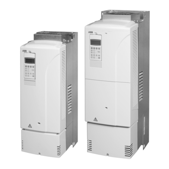
The ACS800-31/U31 What this chapter contains This chapter describes the operating principle and construction of the drive in short. The ACS800-31/U31 The ACS800-31/U31 is wall mountable, low-harmonic drive for controlling AC motors. IP21 (UL type 1) IP20 (UL type open) - Page 32 Frame size R6 without front and connection box covers Frame size R5 without front and connection box covers Location of the line-side converter Location of the motor-side converter RMIO board RMIO board The ACS800-31/U31 Phone: 800.894.0412 - Fax: 888.723.4773 - Web: www.clrwtr.com - Email: [email protected]...
-
Page 33: Terms
The motor control is based on the Direct Torque Control (DTC) method. Two phase currents and DC link voltage are measured and used for the control. The third phase current is measured for earth fault protection. The ACS800-31/U31 Phone: 800.894.0412 - Fax: 888.723.4773 - Web: www.clrwtr.com - Email: [email protected]... -
Page 34: Ac Voltage And Current Waveforms
Each harmonic is presented as compared to fundamental voltage (reference value = 1). n denotes the ordinal number of the harmonic. Test 13 Test 13 Phase current (A) Line-to-line voltage (%) UL12 [%] IL1 [A] The ACS800-31/U31 Phone: 800.894.0412 - Fax: 888.723.4773 - Web: www.clrwtr.com - Email: [email protected]... -
Page 35: Printed Circuit Boards
• current measurement board (GCUR, in frame size R5 only) • charging diode board (GDIO). DDCS communication modules The drive includes an RDCO-03 module in the line-side converter and another RDCO module in the motor-side converter. The ACS800-31/U31 Phone: 800.894.0412 - Fax: 888.723.4773 - Web: www.clrwtr.com - Email: [email protected]... -
Page 36: Main Circuit And Control Interfaces Diagram
Main circuit and control interfaces diagram The ACS800-31/U31 Phone: 800.894.0412 - Fax: 888.723.4773 - Web: www.clrwtr.com - Email: [email protected]... -
Page 37: Fieldbus Control Of The Line-Side Converter
PARAM 23.01 95.08 LCU PAR1 SEL DC VOLT REF 95.09 LCU PAR2 SEL table 23.01 FIELD BUS MCW = Main Control Word MSW = Main Status Word The ACS800-31/U31 Phone: 800.894.0412 - Fax: 888.723.4773 - Web: www.clrwtr.com - Email: [email protected]... -
Page 38: Connection Diagram Of The Rmio Board In The Line-Side Converter
Connection diagram of the RMIO board in the line-side converter Internal connections to the RMIO board for the ACS800 IGBT Supply Control Program are shown below. Do not change the connections. Terminal block size: VREF- Reference voltage -10 VDC, 1 kohm < R <... -
Page 39: Type Code
Type code The type code contains information on the specifications and configuration of the drive. The first digits from left express the basic configuration (e.g. ACS800-31- 0030-5). The optional selections are given thereafter, separated by plus signs (e.g. +E202). The main selections are described below. Not all selections are available for all types. - Page 40 The ACS800-31/U31 Phone: 800.894.0412 - Fax: 888.723.4773 - Web: www.clrwtr.com - Email: [email protected]...
-
Page 41: Mechanical Installation
Mechanical installation Unpacking the unit The drive is delivered in a box that also contains: • plastic bag containing: screws (M3), clamps and cable lugs (2 mm , M3) for grounding the control cable screens • residual voltage warning stickers •... -
Page 42: Moving The Unit
The type designation label is attached to the heat sink and the serial number label to the lower part of the back plate of the unit. Example labels are shown below. Type designation label Serial number label Moving the unit Lift the unit using the lifting holes at the top and bottom. -
Page 43: Before Installation
Before installation The drive must be installed in an upright position with the cooling section facing a wall. Check the installation site according to the requirements below. Refer to chapter Dimensional drawings for frame details. Requirements for the installation site See chapter Technical data for the allowed operation conditions of the drive. -
Page 44: Mounting The Drive On The Wall
Units with vibration dampers In applications with considerable vibration in the frequency range of 50 Hz to 100 Hz, vibration dampers can be used. For units of frame size R5, see ACS800-01/ U1 Vibration Damper Installation Guide [3AFE68295351 (English)]. For units of frame size R6, contact ABB for installation instructions. -
Page 45: Preventing Cooling Air Recirculation
Preventing cooling air recirculation Prevent air recirculation inside and outside the cabinet. Example AREA Main air flow out Air baffle plates COOL AREA Main air flow in Mechanical installation Phone: 800.894.0412 - Fax: 888.723.4773 - Web: www.clrwtr.com - Email: [email protected]... -
Page 46: Unit Above Another
Unit above another Lead the out-coming hot cooling air away from the air input of the drive above. Example max.+40°C (+104°F) Mechanical installation Phone: 800.894.0412 - Fax: 888.723.4773 - Web: www.clrwtr.com - Email: [email protected]... -
Page 47: Planning The Electrical Installation
Note: The installation must always be designed and made according to applicable local laws and regulations. ABB does not assume any liability whatsoever for any installation which breaches the local laws and/or other regulations. Furthermore, if the recommendations given by ABB are not followed, the drive may experience problems that the warranty does not cover. - Page 48 … then the motor voltage with … rating should be … diode supply no resistor braking is in use ACS800-01, -U1, -02, -U2, frequent or long term brake cycles will ACeq1 -04, -04M, -U4 -07, -U7 be used IGBT supply...
-
Page 49: Protecting The Motor Insulation And Bearings
The stress on motor insulation can be avoided by using optional ABB du/dt filters. du/dt filters also reduce bearing currents. -
Page 50: Requirements Table
Requirements table The following table shows how to select the motor insulation system and when an optional ABB du/dt filter, insulated N-end (non-driven end) motor bearings and ABB common mode filters are required. The motor manufacturer should be consulted regarding the construction of the motor insulation and additional requirements for explosion-safe (EX) motors. - Page 51 For motors with higher rated output than what is stated for the particular frame size in EN 50347 (2001) and for IP 23 motors, the requirements of ABB random-wound motor series M3AA, M3AP, M3BP are given below. For other motor types, see the Requirements table above.
-
Page 52: Permanent Magnet Synchronous Motor
Note 7: Drives with an IGBT supply unit If voltage is raised by the drive (this is a parameter selectable function), select the motor insulation system according to the increased intermediate circuit DC voltage level, especially in the 500 V supply voltage range. -
Page 53: Supply Connection
AC power source and the drive. The disconnecting device must be of a type that can be locked to the open position for installation and maintenance work. ACS800-02 and ACS800-U2 with enclosure extension, ACS800-07 and ACS800-U7 These units are equipped with a hand-operated input disconnecting device (disconnecting means) which isolates the drive and the motor from the AC power as standard. -
Page 54: Thermal Overload And Short-Circuit Protection
Thermal overload and short-circuit protection Thermal overload protection The drive protects itself and the input and motor cables against thermal overload when the cables are dimensioned according to the nominal current of the drive. No additional thermal protection devices are needed. WARNING! If the drive is connected to multiple motors, a separate thermal overload switch or a circuit breaker must be used for protecting each cable and motor. -
Page 55: Short-Circuit Protection
1) Size the fuses according to local safety regulations, appropriate input voltage and the rated current of the drive (see Technical data). Standard gG fuses (US: CC or T for the ACS800-U1, ACS800-U11 and ACS800-U31; T or L for the ACS800-U2 and ACS800-U4) will protect the input cable in short-circuit situations, restrict drive damage and prevent damage to adjoining equipment in case of a short-circuit inside the drive. - Page 56 2) Circuit breakers which have been tested by ABB with the ACS800 can be used. Fuses must be used with other circuit breakers. Contact your local ABB representative for approved breaker types and supply network characteristics. The protective characteristics of circuit breakers depend on the type, construction and settings of the breakers.
-
Page 57: Ground Fault Protection
An emergency stop function is optionally available for stopping and switching off the whole drive. Two stop categories according to IEC/EN 60204-1 (1997) are available: immediate removal of power (Category 0 for ACS800-02/U2 and ACS800-07/U7) and controlled emergency stop (Category 1 for ACS800-07/U7). -
Page 58: Prevention Of Unexpected Start
Prevention of Unexpected Start The ACS800-04, ACS800-31/U31 and ACS800-07/U7 can be equipped with an optional Prevention of Unexpected Start function according to standards IEC/ EN 60204-1: 1997; ISO/DIS 14118: 2000 and EN 1037: 1996. The Prevention of Unexpected Start function disables the control voltage of the power semiconductors, thus preventing the inverter from generating the AC voltage required to rotate the motor. -
Page 59: Selecting The Power Cables
Selecting the power cables General rules Dimension the mains (input power) and motor cables according to local regulations: • The cable must be able to carry the drive load current. See chapter Technical data for the rated currents. ° • The cable must be rated for at least 70 C maximum permissible temperature of conductor in continuous use. -
Page 60: Alternative Power Cable Types
Alternative power cable types Power cable types that can be used with the drive are represented below. Recommended Symmetrical shielded cable: three phase conductors A separate PE conductor is required if the conductivity and a concentric or otherwise symmetrically of the cable shield is < 50 % of the conductivity of the constructed PE conductor, and a shield phase conductor. -
Page 61: Additional Us Requirements
Additional US requirements Type MC continuous corrugated aluminum armor cable with symmetrical grounds or shielded power cable must be used for the motor cables if metallic conduit is not used. For the North American market, 600 VAC cable is accepted for up to 500 VAC. 1000 VAC cable is required above 500 VAC (below 600 VAC). -
Page 62: Equipment Connected To The Motor Cable
Stop the drive and wait for the motor to stop before opening a contactor between the output of the drive and the motor when the DTC control mode is selected. See the appropriate ACS800 application program firmware manual for the required parameter settings. Otherwise, the contactor will be damaged. In scalar control, the contactor can be opened with the drive running. -
Page 63: Protecting The Relay Output Contacts And Attenuating Disturbances In Case Of Inductive Loads
Protecting the relay output contacts and attenuating disturbances in case of inductive loads Inductive loads (relays, contactors, motors) cause voltage transients when switched off. The relay contacts on the RMIO board are protected with varistors (250 V) against overvoltage peaks. In spite of this, it is highly recommended to equip inductive loads with noise attenuating circuits [varistors, RC filters (AC) or diodes (DC)] in order to minimize the EMC emission at switch-off. -
Page 64: Selecting The Control Cables
Control panel cable In remote use, the cable connecting the control panel to the drive must not exceed 3 metres (10 ft). The cable type tested and approved by ABB is used in control panel option kits. Planning the electrical installation... -
Page 65: Connection Of A Motor Temperature Sensor To The Drive I/O
3. An external thermistor relay is used. The insulation of the relay must be rated for the same voltage level as the main circuit of the drive. For connection, see ACS800 Firmware Manual. Installation sites above 2000 metres (6562 feet) WARNING! Protect against direct contact when installing, operating and servicing the RMIO board wiring and optional modules attached to the board. -
Page 66: Control Cable Ducts
A diagram of the cable routing is shown below. Motor cable Drive min 300 mm (12 in.) Power cable Input power cable Motor cable 90 ° min 200 mm (8 in.) min 500 mm (20 in.) Control cables Control cable ducts 230 V 230 V (120 V) -
Page 67: Electrical Installation
Electrical installation What this chapter contains This chapter describes the electrical installation procedure of the drive. WARNING! The work described in this chapter may only be carried out by a qualified electrician. Follow the Safety instructions on the first pages of this manual. Ignoring the safety instructions can cause injury or death. -
Page 68: It (Ungrounded) Systems
IT (ungrounded) systems In units with EMC filter options (+E202 and +E200 in the type code), disconnect the filter capacitors before connecting the drive to an ungrounded system. WARNING! If a drive with EMC filter selection +E202 or +E200 is installed on an IT system [an ungrounded power system or a high resistance-grounded (over 30 ohms) power system], the system will be connected to earth potential through the EMC filter capacitors of the drive. -
Page 69: Connecting The Power Cables
Connecting the power cables Diagram Drive OUTPUT INPUT UDC+ UDC V1 W1 U2 V2 W2 (PE) (PE) For alternatives, see Planning the electrical Motor installation: Disconnecting device (disconnecting means) 1), 2) Grounding of the motor cable shield at the motor end If shielded cable is used (not required but For minimum radio frequency interference: recommended), use a separate PE cable (1) or a... -
Page 70: Conductor Stripping Lengths
Conductor stripping lengths Strip the conductor ends as follows to fit them inside the power cable connection terminals. Frame size Stripping length 0.63 1.10 Allowed wire sizes, tightening torques See Technical data: Cable entries. Wall installed units (European version) Power cable installation procedure 1. - Page 71 Views of frame size R5 UDC+ UDC- Electrical installation Phone: 800.894.0412 - Fax: 888.723.4773 - Web: www.clrwtr.com - Email: [email protected]...
- Page 72 Frame sizes R6: Cable lug installation [16 to 70 mm (6 to 2/0 AWG) cables] Remove the screw terminals. Fasten the cable lugs to the remaining bolts with M10 nuts. Isolate the ends of the cable lugs with insulating tape or shrink tubing.
-
Page 73: Wall Installed Units (Us Version)
Wall installed units (US version) 1. Remove the connection box cover. 2. Remove the front cover by releasing the retaining clip with a screw driver and lifting the cover from the bottom outwards. 3. Remove the gland plate by undoing the fastening screws. 4. -
Page 74: Warning Sticker
Wire size Compression lug Crimping tool kcmil/AWG Manufacturer Type Manufacturer Type No. of crimps Burndy YA4C-L4BOX Burndy MY29-3 Ilsco CCL-4-38 Ilsco MT-25 Burndy YA2C-L4BOX Burndy MY29-3 Ilsco CRC-2 Ilsco IDT-12 Ilsco CCL-2-38 Ilsco MT-25 Burndy YA1C-L4BOX Burndy MY29-3 Ilsco CRA-1-38 Ilsco IDT-12 Ilsco... -
Page 75: Connecting The Control Cables
Connecting the control cables Lead the cable through the control cable entry (1). Connect the control cables as described below. Connect the conductors to the appropriate detachable terminals of the RMIO board [refer to chapter Motor control and I/O board (RMIO)]. -
Page 76: 360 Degrees Grounding
360 degrees grounding Insulation Double-shielded cable Single-shielded cable When the outer surface of the shield is covered with non-conductive material • Strip the cable carefully (do not cut the grounding wire and the shield) • Turn the shield inside out to expose the conductive surface. •... -
Page 77: Cabling Of I/O And Fieldbus Modules
Cabling of I/O and fieldbus modules Module As short as possible Shield Note: The RDIO module does not include a terminal for cable shield grounding. Ground the pair cable shields here. Pulse encoder module cabling Note1: If the encoder is of unisolated type, ground the encoder cable at the drive end only. -
Page 78: Fastening The Control Cables And Covers
Fastening the control cables and covers When all control cables are connected, fasten them together with cable ties. Units with a connection box: fasten the cables to the entry plate with cable ties. Units with a gland box: tighten the clamping nuts of the cable glands. Fasten the connection box cover. -
Page 79: Installation Of Agps Board (Prevention Of Unexpected Start, +Q950)
Installation of AGPS board (Prevention of Unexpected Start, +Q950) What this chapter contains This chapter describes the electrical installation of the optional Prevention of Unexpected Start function (+Q950) of the drive. Prevention of Unexpected Start (+Q950) The optional Prevention of Unexpected Start function includes an AGPS board which is connected to the drive and an external power supply. - Page 80 Connect the AGPS board as follows: • Remove the enclosure cover by undoing the fixing screws (1). • Ground the bottom plate of the enclosure or via terminal X1:1 of the AGPS board. • Connect the cable delivered with the kit between terminal block X2 of the AGPS board (2) and drive terminal block X41.
-
Page 81: Circuit Diagram
Circuit diagram This circuit diagram shows how the AGPS-11 kit is installed. Drive 115/230 VAC 3AFE00374994 Installation of AGPS board (Prevention of Unexpected Start, +Q950) Phone: 800.894.0412 - Fax: 888.723.4773 - Web: www.clrwtr.com - Email: [email protected]... -
Page 82: Dimensional Drawing
Dimensional drawing The dimensional drawing of the AGPS board is shown below. Installation of AGPS board (Prevention of Unexpected Start, +Q950) Phone: 800.894.0412 - Fax: 888.723.4773 - Web: www.clrwtr.com - Email: [email protected]... -
Page 83: Motor Control And I/O Board (Rmio)
• specifications of the inputs and outputs of the board. To which products this chapter applies This chapter applies to ACS800 units which employ RMIO-01 board from revision J onwards and RMIO-02 board from revision H onwards. Note for the ACS800-02 with enclosure extension and the ACS800-07 The connections for the RMIO board shown below apply also to optional terminal block X2 available for the ACS800-02 and ACS800-07. -
Page 84: Note On External Power Supply
Note on external power supply External +24 V power supply for the RMIO board is recommended if • the application requires a fast start after connecting the input power supply • fieldbus communication is required when the input power supply is disconnected. The RMIO board can be supplied from an external power source via terminal X23 or X34 or via both X23 and X34. -
Page 85: External Control Connections (Non-Us)
External control connections (non-US) External control cable connections to the RMIO board for the ACS800 Standard Application Program (Factory Macro) are shown below. For external control connections of other application macros and programs, see the appropriate Firmware Manual. RMIO RMIO VREF- Reference voltage -10 VDC, 1 kohm <... -
Page 86: External Control Connections (Us)
External control connections (US) External control cable connections to the RMIO board for the ACS800 Standard Application Program (Factory Macro US version) are shown below. For external control connections of other application macros and programs, see the appropriate Firmware Manual. -
Page 87: Rmio Board Specifications
RMIO board specifications Analogue inputs With Standard Application Program two programmable differential current inputs (0 mA / 4 mA ... 20 mA, R = 100 ohm) and one programmable differential voltage input (-10 V / 0 V / 2 V ... +10 V, R >... -
Page 88: Relay Outputs
Maximum continuous current 2 A rms Isolation test voltage 4 kVAC, 1 minute DDCS fibre optic link With optional communication adapter module RDCO. Protocol: DDCS (ABB Distributed Drives Communication System) 24 VDC power input Voltage 24 VDC ± 10 %... - Page 89 Isolation and grounding diagram (Test voltage: 500 V AC) VREF- AGND VREF+ AGND AI1+ Common mode AI1- voltage between AI2+ channels ±15 V AI2- AI3+ AI3- AO1+ AO1- AO2+ AO2- Jumper J1 settings: DGND1 All digital inputs share a common ground.
- Page 90 Motor control and I/O board (RMIO) Phone: 800.894.0412 - Fax: 888.723.4773 - Web: www.clrwtr.com - Email: [email protected]...
-
Page 91: Installation Checklist
Installation checklist What this chapter contains This chapter contains an installation checklist. Installation checklist Check the mechanical and electrical installation of the drive before start-up. Go through the checklist below together with another person. WARNING! Only qualified electricians are allowed to commission the drive. Read and follow the Safety instructions on the first pages of this manual. - Page 92 Check... The motor connections at U2, V2 and W2 and their tightening torques are OK. The motor cable is routed away from other cables. There are no power factor compensation capacitors in the motor cable. The external control connections inside the drive are OK. There are no tools, foreign objects or dust from drilling inside the drive.
-
Page 93: Start-Up And Use
Start-up and use What this chapter contains This chapter describes the start-up procedure and use of the drive. Start-up and use WARNING! Only qualified electricians are allowed to commission the drive. Read and follow the Safety instructions on the first pages of this manual. Ignoring the safety instructions can cause injury or death. -
Page 94: Control Panel
Control panel The drive is equipped with a control panel (type CDP-312R). The CDP-312R is the user interface of the line-side converter and the motor-side converter of the drive, providing the essential controls such as Start/Stop/Direction/Reset/Reference, and the parameter settings for the units’ application programs. More information on using the panel can be found in the Firmware Manual delivered with the drive. -
Page 95: To Control The Motor-Side Converter
To control the motor-side converter... Step Action Press key Display (example) Enter the Drive Selection Mode. ACS 800 0050_5LR DRIVE IXXR7xxx ID-NUMBER 2 Scroll to ID number 1. ACS 800 0050_5MR ACXR7xxx ID-NUMBER 1 Verify the change to the motor-side converter. ->... - Page 96 Start-up and use Phone: 800.894.0412 - Fax: 888.723.4773 - Web: www.clrwtr.com - Email: [email protected]...
-
Page 97: Actual Signals And Parameters
Actual signals and parameters What this chapter contains This chapter contains listings of parameters specific to the ACS800-31 and ACS800- U31. Line-side converter actual signals and parameters in the motor-side converter application program This section describes the actual signals and parameters of the line-side converter control program which are copied to the motor-side converter application program. -
Page 98: Parameters
Parameters Name/Value Description FbEq Def. 95 HARDWARE SPECIF Line converter references and actual signal selections. 95.06 LCU Q POW REF Reactive power reference for the line converter i.e. the value for par. 24.02 Q POWER REF2 in the IGBT Supply Control Program. Scaling example 1: 10000 equals to a value of 10000 of parameter 24.02 Q POWER REF2 and 100% of par. -
Page 99: Acs800-31/U31 Specific Parameters In The Igbt Supply Control Program
ACS800-31/U31 specific parameters in the IGBT Supply Control Program The signals and parameters of the IGBT Supply Control Program which are specific to the ACS800-31 and ACS800-U31 are described in the tables below. These parameters need not be set in a normal start-up. For more information on parameters of the IGBT Supply Control Program, refer to IGBT Supply Control Program Firmware Manual [3AFE68315735 (English)]. -
Page 100: 31 Automatic Reset
Name/Value Description T./FbEq Def. 31 AUTOMATIC RESET Automatic fault reset. Automatic resets are possible only for certain fault types and when the automatic reset function is activated for that fault type. The automatic reset function is not operational if the drive is in local control (L visible on the first row of the control panel display). -
Page 101: Fixed Parameters With The Acs800-31 And Acs800-U31
Fixed parameters with the ACS800-31 and ACS800-U31 When the IGBT Supply Control Program is loaded into the ACS800-31 or ACS800- U31, the following parameters are set to the default values given in the table below. Parameter Default value If changed, 11.01... - Page 102 Actual signals and parameters Phone: 800.894.0412 - Fax: 888.723.4773 - Web: www.clrwtr.com - Email: [email protected]...
-
Page 103: What This Chapter Contains
Ignoring the safety instructions can cause injury or death. Maintenance intervals If installed in an appropriate environment, the drive requires very little maintenance. This table lists the routine maintenance intervals recommended by ABB. Maintenance Interval Instruction... -
Page 104: Heatsink
See the appropriate ACS800 firmware manual for an actual signal which indicates the hours of usage of the fan. For resetting the running time signal after a fan replacement, please contact ABB. -
Page 105: Fan Replacement (R5, R6)
Fan replacement (R5, R6) 1. Loosen the fastening screws of the top plate. 2. Push the top plate backwards. 3. Lift the top plate up. 4. Disconnect the fan supply wires (detachable connector). 5. Lift the fan up. 6. Install the new fan in reverse order. Additional fan Replacement (R5) Remove the front cover. -
Page 106: Replacement (R6)
It is not possible to predict a capacitor failure. Capacitor failure is usually followed by a mains fuse failure or a fault trip. Contact ABB if capacitor failure is suspected. Replacements are available from ABB. Do not use other than ABB specified spare parts. -
Page 107: Fault Tracing
Fault tracing What this chapter contains This chapter describes the fault tracing of the line-side converter. For motor-side converter fault tracing, see the appropriate application program firmware manual. Faults and warnings displayed by the CDP-312R Control Panel The control panel will display the warnings and faults of the unit (i.e. line-side converter or motor-side converter) the panel is currently controlling. - Page 108 Fault tracing Phone: 800.894.0412 - Fax: 888.723.4773 - Web: www.clrwtr.com - Email: [email protected]...
-
Page 109: Technical Data
Technical data What this chapter contains This chapter contains the technical specifications of the drive, e.g. the ratings, sizes and technical requirements, provisions for fulfilling the requirements for CE and other markings and warranty policy. Technical data Phone: 800.894.0412 - Fax: 888.723.4773 - Web: www.clrwtr.com - Email: [email protected]... -
Page 110: Iec Data
IEC data Ratings The IEC ratings for the ACS800-31 with 50 Hz and 60 Hz supplies are given below. The symbols are described below the table. ACS800-31 size Nominal Light-overload Heavy-duty use Frame Air flow Heat overload ratings size dissipation cont.max... -
Page 111: Symbols
Symbols Nominal ratings continuous rms output current. No overload capability at 40°C. cont.max maximum output current. Available for 10 s at start, otherwise as long as allowed by drive temperature. Typical ratings: No-overload use typical motor power. The power ratings apply to most IEC 34 motors at the nominal voltage, cont.max 230 V, 400 V, 500 V or 690 V. -
Page 112: Mains Cable Fuses
Note 1: In multicable installations, install only one fuse per phase (not one fuse per conductor). Note 2: Larger fuses must not be used. Note 3: Fuses from other manufacturers can be used if they meet the ratings. ACS800-31 size Input Fuse... -
Page 113: Cable Types
Cable types The table below gives copper and aluminium cable types for different load currents. Cable sizing is based on max. 9 cables laid on a cable ladder side by side, ambient temperature 30°C, PVC insulation, surface temperature 70°C (EN 60204-1 and IEC 60364-5-2/2001). -
Page 114: Nema Data
NEMA data Ratings The NEMA ratings for the ACS800-U31 and ACS800-31 with 60 Hz supplies are given below. The symbols are described below the table. For sizing, derating and 50 Hz supplies, see IEC data on page 102. ACS800-U31 size... -
Page 115: Input Cable Fuses
Note 1: In multicable installations, install only one fuse per phase (not one fuse per conductor). Note 2: Larger fuses must not be used. Note 3: Fuses from other manufacturers can be used if they meet the ratings. ACS800-U31 type Input Fuse... -
Page 116: Cable Types
Cable types Cable sizing is based on NEC Table 310-16 for copper wires, 75°C (167°F) wire insulation at 40°C (104°F) ambient temperature. Not more than three current-carrying conductors in raceway or cable or earth (directly buried). For other conditions, dimension the cables according to local safety regulations, appropriate input voltage and the load current of the drive. -
Page 117: Input Power Connection
Input power connection Voltage (U 208/220/230/240 VAC 3-phase ± 10% for 230 VAC units 380/400/415 VAC 3-phase ± 10% for 400 VAC units 380/400/415/440/460/480/500 VAC 3-phase ± 10% for 500 VAC units 525/550/575/600/660/690 VAC 3-phase ± 10% for 690 VAC units Prospective short-circuit Maximum allowed prospective short-circuit current in the supply is 65 kA in a second current (IEC 60439-1,... -
Page 118: Motor Connection
Motor connection Voltage (U 0 to U , 3-phase symmetrical, U at the field weakening point Frequency DTC mode: 0 to 3.2 · f . Maximum frequency 300 Hz. Nmains · f Nmotor Nmotor : frequency at field weakening point; U : mains (input power) voltage;... -
Page 119: Ambient Conditions
Ambient conditions Environmental limits for the drive are given below. The drive is to be used in a heated, indoor, controlled environment. Operation Storage Transportation installed for stationary use in the protective package in the protective package Installation site altitude 0 to 4000 m (13123 ft) above sea level [above 1000 m (3281 ft), see section... -
Page 120: Materials
EU. They must be removed and handled according to local regulations. For further information on environmental aspects and more detailed recycling instructions, please contact your local ABB distributor. Applicable standards The drive complies with the following standards. The compliance with the European Low Voltage Directive is verified according to standards EN 50178 and EN 60204-1. -
Page 121: Ce Marking
CE marking A CE mark is attached to the drive to verify that the unit follows the provisions of the European Low Voltage and EMC Directives (Directive 73/23/EEC, as amended by 93/68/EEC and Directive 89/336/ EEC, as amended by 93/68/EEC). Definitions EMC stands for Electromagnetic Compatibility. -
Page 122: Second Environment (Drive Of Category C3)
Equipment 2. An EMC plan for preventing disturbances is drawn up for the installation. A template is available from the local ABB representative. 3. The motor and control cables are selected as specified in the Hardware Manual. 4. The drive is installed according to the instructions given in the Hardware Manual. -
Page 123: C-Tick" Marking
“C-tick” marking “C-tick” marking is required in Australia and New Zealand. A “C-tick” mark is attached to each drive in order to verify compliance with the relevant standard (IEC 61800-3 (2004) – Adjustable speed electrical power drive systems. Part 3: EMC requirements and specific test methods), mandated by the Trans- Tasman Electromagnetic Compatibility Scheme. -
Page 124: Second Environment (Drive Of Category C3)
Equipment 2. An EMC plan for preventing disturbances is drawn up for the installation. A template is available from the local ABB representative. 3. The motor and control cables are selected as specified in the Hardware Manual. 4. The drive is installed according to the instructions given in the Hardware Manual. -
Page 125: Ul/Csa Markings
If you have any questions concerning your ABB drive, please contact the local distributor or ABB office. The technical data, information and specifications are valid at the time of printing. The manufacturer reserves the right to modifications without prior notice. - Page 126 Technical data Phone: 800.894.0412 - Fax: 888.723.4773 - Web: www.clrwtr.com - Email: [email protected]...
-
Page 127: Dimensional Drawings
Dimensional drawings The dimensions are given in millimetres and [inches]. Dimensional drawings Phone: 800.894.0412 - Fax: 888.723.4773 - Web: www.clrwtr.com - Email: [email protected]... -
Page 128: Frame Size R5 (Ip21, Ul Type Open, Ul Type 1)
Frame size R5 (IP21, UL type open, UL type 1) Dimensional drawings Phone: 800.894.0412 - Fax: 888.723.4773 - Web: www.clrwtr.com - Email: [email protected]... -
Page 129: Frame Size R6 (Ip21, Ul Type Open, Ul Type 1)
Frame size R6 (IP21, UL type open, UL type 1) Dimensional drawings Phone: 800.894.0412 - Fax: 888.723.4773 - Web: www.clrwtr.com - Email: [email protected]... - Page 130 Dimensional drawings Phone: 800.894.0412 - Fax: 888.723.4773 - Web: www.clrwtr.com - Email: [email protected]...
-
Page 131: Resistor Braking
Resistor braking What this chapter contains This chapter describes how to select, protect and wire external brake choppers and resistors for the drive. The chapter also contains installation instructions and the technical data. How to select the correct drive/chopper/resistor combination Refer to NBRA-6xx Braking Choppers Installation and Start-up Guide [3AFY58920541 (English)]. -
Page 132: External Brake Chopper And Resistor(S) For The Acs800-31/U31
External brake chopper and resistor(s) for the ACS800-31/U31 The nominal ratings for dimensioning the brake resistors for the ACS800-31 and ACS800-U31 are given below at an ambient temperature of 40°C (104°F). ACS800-31 Chopper Brake resistor Cable Degree of protection brmax... -
Page 133: Brake Chopper And Resistor Installation
Below is a simple example wiring diagram. L1 L2 Fuses ACS800 U1 V1 W1 Thermal switch (standard Θ in ABB resistors) Resistor braking Phone: 800.894.0412 - Fax: 888.723.4773 - Web: www.clrwtr.com - Email: [email protected]... -
Page 134: Brake Circuit Commissioning
OFF2 STOP. For the use of the brake resistor overload protection (parameters 27.02...27.05), consult an ABB representative. WARNING! If the drive is equipped with a brake chopper but the chopper is not enabled by parameter setting, the brake resistor must be disconnected because the protection against resistor overheating is then not in use. -
Page 135: External +24 V Power Supply For The Rmio Boards Via Terminal X34
External +24 V power supply for the RMIO boards via terminal X34 What this chapter contains This chapter describes how to connect an external +24 V power supply for the RMIO boards of the motor-side and line-side converters via terminal X34. For current consumption of the RMIO board, see chapter Motor control and I/O board (RMIO). -
Page 136: Connecting +24 V External Power Supply
Connecting +24 V external power supply RMIO board of the motor-side converter 1. Break off the tab covering the +24 VDC power input connector with pliers. 2. Pull the connector outwards. 3. Disconnect the wires from the connector (keep the connector for later use). 4. - Page 137 RMIO board Connection of a two-way connector RMIO board Connection of a three-way connector External +24 V power supply for the RMIO boards via terminal X34 Phone: 800.894.0412 - Fax: 888.723.4773 - Web: www.clrwtr.com - Email: [email protected]...
-
Page 138: Rmio Board Of The Line-Side Converter
RMIO board of the line-side converter Frame size R5 The location of terminal X34 in the line-side converter is shown below. Connect the external +24 V supply to the board as described in steps 2 to 8 in section RMIO board of the motor-side converter. - Page 139 9. Lift the upper plastic cover off. 10. Connect the external +24 V supply to the board as described in steps 2 to 5, 7 and 8 in section RMIO board of the motor-side converter. 11. Reconnect all disconnected cables and fasten the covers in reverse order. External +24 V power supply for the RMIO boards via terminal X34 Phone: 800.894.0412 - Fax: 888.723.4773 - Web: www.clrwtr.com - Email: [email protected]...