ABB ACS310 Quick Start Manual
Plc and drives integration using modbus rtu
Hide thumbs
Also See for ACS310:
- User manual (376 pages) ,
- User's manual and safety manual (40 pages) ,
- Installation instructions (4 pages)
Table of Contents
Table of Contents

Related Manuals for ABB ACS310


Summary of Contents for ABB ACS310
- Page 1 Quickstart Guide ABB PLC and drives integration using Modbus RTU ...
-
Page 2: Table Of Contents
Quickstart Guide ABB PLC and drives integration using Modbus RTU Contents Introduction...................................4 Safety instructions .................................4 Limitations ..................................4 Fieldbus grounding ..............................6 Fieldbus shield ................................6 End termination.................................6 Pull up/pull down resistors............................6 Drives with embedded fieldbus..........................7 Fieldbus modules for ABB drives..........................8 Common recommendations............................8 ABB cable TK505................................9 AC500 COM1 – Master at the bus line end ......................11 AC500 COM2 – Master at the bus line end ......................11 AC500‐eCo COM1 – Master at the bus line end....................11 AC500‐eCo COM2 – Master at the bus line end....................12 Drive configuration..............................13 Starting up ACS310 drives with embedded Modbus RTU ..................14 Starting up ACS355 drives with FMBA‐01 Modbus RTU adapter ................15... - Page 3 Quickstart Guide ABB PLC and drives integration using Modbus RTU Library Manager ..............................26 PLC logic................................27 Download program to PLC...........................32 Create boot project .............................33 Test the program ..............................34 Read and write more data between PLC and drive (optional) ................36 Visualizations ...............................43 Add more drives (optional)..........................46 Actualization rate ..............................47 Other useful documentation ............................47 Revision ..................................47 Modbus RTU ‐ 3 ‐ PLC and drives integration ...
-
Page 4: Introduction
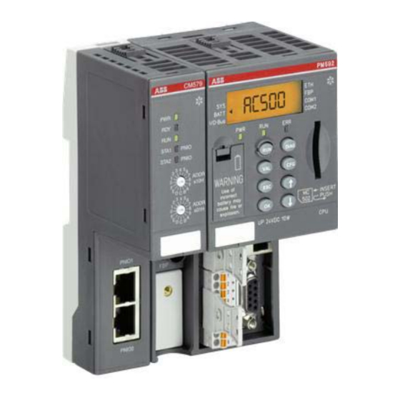
Introduction This guide will take you through the hardware installation and configuration of ABB ACS Drives and PLC in order to prepare for Modbus RTU control. ABB‐specific ready‐made function blocks and visualizations from the PS553‐ DRIVES library will be used for the control of the drives. While the guide is applicable to all AC500 PLCs and all Modbus RTU compatible ABB ACS drives, the example is built up with an AC500‐eCo PLC and an ACS355 drive. ... - Page 5 Quickstart Guide ABB PLC and drives integration using Modbus RTU Setup example Control Builder Plus ETHERNET or serial connection AC500 PLC ABB ACS Drives ABB Modbus RTU modules or embedded Modbus RTU Modbus RTU ‐ 5 ‐ PLC and drives integration ...
-
Page 6: Fieldbus Grounding
Quickstart Guide ABB PLC and drives integration using Modbus RTU Hardware physical connection In the following chapter, physical connection of the hardware will be explained. Fieldbus grounding For AC500, which has opto‐isolated COM interfaces, it is recommended not to connect the ground. For AC500‐ eCo, where the COM interfaces are not opto‐isolated, it is recommended to connect the ground at one place, ... -
Page 7: Drives With Embedded Fieldbus
Quickstart Guide ABB PLC and drives integration using Modbus RTU AC500 and AC500eCo COM port overview AC500 AC500‐eCo CM574‐RS COM1 COM2 COM1 COM2 COM1=COM2 (optional) (see COM1 of AC500, except pull‐ up/pull‐down) COM Voltage level 5 V 5 V 3,3 V 3,3 V 5V Opto‐isolated YES YES ... -
Page 8: Fieldbus Modules For Abb Drives
Quickstart Guide ABB PLC and drives integration using Modbus RTU Fieldbus modules for ABB drives The following ABB drives Modbus RTU modules have an option to activate built‐in end termination and pull‐ up/pull‐down resistors. RMBA‐01 (used with for instance ACS550 and ACS800) FSCA‐01 (used with for instance ACS880 and ACSM1) The following ABB drives Modbus RTU module does not have an option to activate built‐in end resistors including pull‐up/pull‐down resistors. ... -
Page 9: Abb Cable Tk505
Quickstart Guide ABB PLC and drives integration using Modbus RTU Bus line Construction 2 cores, twisted, with common shield Conductor cross section >0.22 mm (24 AWG) ‐recommendation 0.5 mm corresponds to Ø0.8 mm Twisting rate <10/meter (symmetrically twisted) Core insulation Polyethylene (PE) Resistance per core <100 Ω/km Characteristic impedance Appr. 120 Ω (100…150 Ω) Capacitance between the cores <55 nF/km (if higher, then max bus length must be reduced) Terminating resistors 120 Ω, ¼ W at both line ends Remarks ... - Page 10 Quickstart Guide ABB PLC and drives integration using Modbus RTU Installation examples Best connection of shield is to connect directly to the mounting plate of the cabinet as near as possible to the AC500. The mounting plate has to be connected to common earth in the cabinet at one point. or Modbus RTU ‐ 10 ‐ PLC and drives integration ...
-
Page 11: Ac500 Com1 - Master At The Bus Line End
Quickstart Guide ABB PLC and drives integration using Modbus RTU AC500 COM1 – Master at the bus line end AC500 COM2 – Master at the bus line end AC500eCo COM1 – Master at the bus line end Modbus RTU ‐ 11 ‐ PLC and drives integration ... -
Page 12: Ac500-Eco Com2 - Master At The Bus Line End
Quickstart Guide ABB PLC and drives integration using Modbus RTU AC500eCo COM2 – Master at the bus line end Modbus RTU ‐ 12 ‐ PLC and drives integration ... -
Page 13: Drive Configuration
Quickstart Guide ABB PLC and drives integration using Modbus RTU Drive configuration Drives without embedded Modbus RTU need to be equipped with Modbus RTU adapter according to actual drive type. The following drive configuration steps will adapt the drive to Modbus RTU control based on ABB‐specific drives library PS553‐DRIVES. Drive parameters can be set from the drive’s control panel or from drive‐specific pc tool (DriveWindow Light for ACS355 and ACS550, DriveStudio for ACS850 and ACSM1, Drive Composer for ACS880 and DriveWindow for ACS800). Note! All parameter settings are based on drive default settings. If the drive has been parameterized previously, return to default settings before continuing. It can be done by: Changing macro (and then changing back again) in parameter 99.02 for ACS310, ACS355 and ACS550. Setting parameter 99.03 APPLIC RESTORE to YES in ACS800. Setting parameter 16.04 Param restore to Restore defs in ACS850 and ACSM1. Setting parameter 96.06 Parameter restore to Restore defaults in ACS880. Modbus RTU ‐ 13 ‐ PLC and drives integration ... -
Page 14: Starting Up Acs310 Drives With Embedded Modbus Rtu
Quickstart Guide ABB PLC and drives integration using Modbus RTU Starting up ACS310 drives with embedded Modbus RTU Minimum required parameter settings (based on factory default settings) Parameter Description Setting Comment 98.02 COMM PROT SEL STD Activates fieldbus communication MODBUS 53.02 EFB STATION ID [Address] Modbus RTU node address of the drive 53.03 EFB BAUD RATE 19.2 kbit/s Transfer rate of the link. Same baud rate must be (example) defined in the Modbus RTU master. 53.04 EFB PARITY 8 NONE 1 ... -
Page 15: Starting Up Acs355 Drives With Fmba-01 Modbus Rtu Adapter
Quickstart Guide ABB PLC and drives integration using Modbus RTU Starting up ACS355 drives with FMBA01 Modbus RTU adapter Minimum required parameter settings (based on factory default settings) Parameter Description Setting Applic Macro Comment ”AC500 MODBUS” *) 98.02 COMM PROT SEL STD STD Activates fieldbus module MODBUS MODBUS 53.02 EFB STATION ID [Address] 2 Modbus RTU node address of the drive 53.03 EFB BAUD RATE 19.2 kbit/s ... - Page 16 Quickstart Guide ABB PLC and drives integration using Modbus RTU Starting up ACS550 with embedded Modbus RTU Minimum required parameter settings (based on factory default settings) Parameter Description Setting Comment 98.02 COMM PROT SEL EXT FBA Activates fieldbus communication 53.02 EFB STATION ID [Address] Modbus RTU node address of the drive 53.03 EFB BAUD RATE 19.2 kbit/s Transfer rate of the link. Same baud rate must be (example) defined in the Modbus RTU master. 53.04 EFB PARITY 8 NONE 1 Parity and stop bits. Same parity and stop bits must (example) ...
-
Page 17: Starting Up Acs800 Drives With Rmba-01 Modbus Rtu Adapter
Quickstart Guide ABB PLC and drives integration using Modbus RTU Starting up ACS800 drives with RMBA01 Modbus RTU adapter Minimum required parameter settings (based on factory default settings) Parameter Description Setting Comment 98.02 COMM. MODULE STD Activates fieldbus module LINK MODBUS 98.07 COMM PROFILE ABB DRIVES Communication profile “ABB Drives” 52.01 STATION [Address] Modbus RTU node address of the drive NUMBER 52.02 BAUDRATE 19.2 kbit/s ... -
Page 18: Starting Up Acs850, Acq810 Drives With Embedded Modbus Rtu
Quickstart Guide ABB PLC and drives integration using Modbus RTU Starting up ACS850, ACQ810 drives with embedded Modbus RTU Minimum required parameter settings (based on factory default settings) Parameter Description Setting Comment 50.15 Fb cw used P.02.36 Selects the address of the fieldbus Control Word in use. 58.01 Protocol ena sel Modbus RTU Initializes embedded fieldbus communication. Drive‐to‐drive link operation (parameter group 57) is automatically disabled. 58.03 Node address [Address] Modbus RTU node address of the drive 58.04 Baud rate 19.2 kbit/s ... -
Page 19: Starting Up Acs880 Drives With Fsca-01 Modbus Rtu Adapter
Quickstart Guide ABB PLC and drives integration using Modbus RTU Starting up ACS880 drives with FSCA01 Modbus RTU adapter Minimum required parameter settings (based on factory default settings) Parameter Description Setting Comment 50.01 FBA A enable Enable Activates fieldbus module 51.02 PROTOCOL/PROFIL ABB Drives Communication profile “ABB Drives” E Classic or Enhanced 51.03 STATION ID [Address] Modbus RTU node address of the drive 51.04 BAUD RATE ... -
Page 20: Starting Up Acsm1 Drives With Fsca-01 Modbus Rtu Adapter
Quickstart Guide ABB PLC and drives integration using Modbus RTU Starting up ACSM1 drives with FSCA01 Modbus RTU adapter Minimum required parameter settings (based on factory default settings) Parameter Description Setting Comment 50.01 FBA ENABLE Enable Activates fieldbus module 51.02 PROTOCOL/PROFILE ABB Drives Communication profile “ABB Drives” Classic 51.03 STATION ID [Address] Modbus RTU node address of the drive 51.04 BAUD RATE 19.2 kbit/s Transfer rate of the link. Same baud rate must be ... -
Page 21: Install Drives Library
Quickstart Guide ABB PLC and drives integration using Modbus RTU Install drives library Note! In Control Builder Plus V2.3 and later, the ACSDrivesBase library is already installed. You can find it in the subfolder “PS553‐DRIVES” of the default library folder (see left picture below) Note! The version of the library can differ, nevertheless the name will stay the same! Creation date and main changes can be seen in the library manager of CODESYS only. For older Versions of Control Builder Plus you can download the installation package in the following way from: ... -
Page 22: Control Builder Plus For Plc And Drives
Quickstart Guide ABB PLC and drives integration using Modbus RTU Control Builder Plus for PLC and Drives Start the “Control Builder Plus” PC tool for PLC configuration and go through the following steps. Hardware configuration File → New Project → Choose “AC500 project” and name the project. Choose PLC device according to your equipment and then “Add device”. ... - Page 23 Quickstart Guide ABB PLC and drives integration using Modbus RTU Double‐click “COMX_Modbus” to configure the Modbus settings. Do at least the following settings: Set “Baudrate”, “Parity”, “Data bits” and “Stop bits” (1) according to settings in actual drive. Set “Operation mode” to “Master” and “Address” to “0” (2). Set “RTS control” to “Telegram” (3) (=RS485 ‐ in AC500‐eCo this is already set) Modbus RTU ‐ 23 ‐ PLC and drives integration ...
-
Page 24: Ip Configuration Of Cpu (For Ethernet Connection Between Pc And Plc)
Quickstart Guide ABB PLC and drives integration using Modbus RTU IP configuration of CPU (for Ethernet connection between PC and PLC) If the CPU has an Ethernet port and the CPU IP address has not already been configured, follow the steps below. De‐activate the firewall of the PC, or allow the connection if question comes up. Connect an Ethernet cable between PC and PLC (or via a switch). Open the IP configuration tool from the “Tools” menu and press the “Scan” button. ... -
Page 25: Codesys
Quickstart Guide ABB PLC and drives integration using Modbus RTU CODESYS Double‐click “AC500” from the Device tree in the Control Builder Plus project to open CODESYS. CODESYS tabs In CODESYS there are four different tabs for programming, configuration, etc. 1. POUs (Program Organization Units): This tab contains your Functions, Function blocks and Programs. 2. Data types: In this tab, along with the standard data types you can define your own user‐specific data ... -
Page 26: Library Manager
Quickstart Guide ABB PLC and drives integration using Modbus RTU Library Manager Open the Library Manager by double‐clicking “Library Manager” from the “Resources” tab. Right‐click in the library field and choose “Additional Library”. Select the “ACSDrivesBase_AC500_V20.lib” and “ACSDrivesComModRTU_AC500_V20.lib” library files from the ... -
Page 27: Plc Logic
Quickstart Guide ABB PLC and drives integration using Modbus RTU PLC logic The following program handles a Speed control drive application. Compile your project, choose “Rebuild all” from the “Project” menu. Right‐click “PLC_PRG” in the “POUs” tab and choose “Convert Object”. Choose Target Language “FBD” and click “OK”. Right‐click in the POUs field and choose “Add Object”. Set Type of POU to “Program” and Language of the POU to “FBD”, give the new Program a suitable name and click “OK”. Modbus RTU ‐ 27 ‐ PLC and drives integration ... - Page 28 Quickstart Guide ABB PLC and drives integration using Modbus RTU Double‐click “PLC_PRG” (1) to open the main program. Select the dotted box (2) in Network 0001 and insert a box (3). Write the name of your new Program (Drive1 (PRG) in the example) to call for it from the main program. Double‐click your new program and add a box as described above. This time, press F2 while the block title is ...
- Page 29 Quickstart Guide ABB PLC and drives integration using Modbus RTU Double‐click “Global_Variables” in the “Resources” tab (1) and create a global variable for the Modbus token handling of type “ACS_MOD_TOKEN_TYPE” (2). This variable will be used for connecting the drive to a certain ...
- Page 30 Quickstart Guide ABB PLC and drives integration using Modbus RTU Modbus RTU ‐ 30 ‐ PLC and drives integration ...
- Page 31 Quickstart Guide ABB PLC and drives integration using Modbus RTU Create a second network (Ctrl +T) in the same program and add the block “ACS_DRIVES_CTRL_STANDARD” in the same way as for “ACS_COM_MOD_RTU”. Connect the function block inputs and outputs according to your needs. In the example below: The block will always be enabled The drive is started by the variable “DriveStart” Emergency stop functions are not used in this example Ramp stop by setting “DriveStart” = FALSE Coast stop by setting “DriveCoastStop” = TRUE Fault reset by setting “DriveResetFault” = TRUE (positive edge). Speed reference is set by the variable “SpeedRef” as a value between ‐20000 and 20000, where 20000 ...
-
Page 32: Download Program To Plc
Quickstart Guide ABB PLC and drives integration using Modbus RTU Download program to PLC Save the program and choose “Communication Parameters” from the “Online” menu. Set communication Parameters according to your online connection. In the example below, the “Address” 192.168.0.10 corresponds to the IP address of actual CPU and is also the default IP address of AC500 CPUs. Note that in case of Ethernet connection, the IP address of your PC port or Ethernet adapter should belong to the same subnet as the CPU, ... -
Page 33: Create Boot Project
Quickstart Guide ABB PLC and drives integration using Modbus RTU Create boot project In “online” mode (Login), choose “Create boot project” from the “Online” menu. With this command, the compiled project is stored to the flash in such a way that the PLC will load it automatically when restarted. Modbus RTU ‐ 33 ‐ PLC and drives integration ... -
Page 34: Test The Program
Quickstart Guide ABB PLC and drives integration using Modbus RTU Test the program If the drive has an active fault (“TRIPPED” output is colored blue) (1), then try to reset by setting the “RESET” input = TRUE (2). Double‐click the input variable and choose “Write Values” from the “Online” menu (3). When the “READY” output is TRUE (blue) (1), then set the “SPEED_REF” input (2) to desired speed value and “START” input = TRUE (3). Write values from the Online menu or Ctrl+F7. Check that the drive starts and follows ... - Page 35 Quickstart Guide ABB PLC and drives integration using Modbus RTU Modbus RTU ‐ 35 ‐ PLC and drives integration ...
-
Page 36: Read And Write More Data Between Plc And Drive (Optional)
Quickstart Guide ABB PLC and drives integration using Modbus RTU Read and write more data between PLC and drive (optional) While the already implemented function block “ACS_COM_MOD_RTU” has built‐in functionality to read more data/parameters from pre‐determined Modbus register addresses in the drive, the function blocks ... - Page 37 Quickstart Guide ABB PLC and drives integration using Modbus RTU The parameter values from the drive are then written to the new array variable (6). Modbus RTU ‐ 37 ‐ PLC and drives integration ...
- Page 38 Quickstart Guide ABB PLC and drives integration using Modbus RTU Example Read drive data with “ACS_MOD_READ_N_PRM” Values are read from Modbus register addresses according to user choice. No additional parameter settings in the drive are necessary. Create a new network in the same program (POU) and add the block “ACS_MOD_READ_N_PRM”. Modbus RTU ‐ 38 ‐ PLC and drives integration ...
- Page 39 Quickstart Guide ABB PLC and drives integration using Modbus RTU Set function block inputs according to: EN = TRUE (1) → The block will always be enabled. PRIO = Left unconnected. NVAR = Number of parameters to be read (2) → 2 parameters will be read in this example. PRM_NUM = Start address of parameters to be read (3) → parameters 12.02 and 12.03 will be read in this example. DATA is connected via an “ADR” block to a new variable (4). Press the “…” button (5) and choose type ...
- Page 40 Quickstart Guide ABB PLC and drives integration using Modbus RTU Note! Several “ACS_MOD_READ_N_PRM” blocks can be activated at the same time. See example below. Modbus RTU ‐ 40 ‐ PLC and drives integration ...
- Page 41 Quickstart Guide ABB PLC and drives integration using Modbus RTU Example Write drive data with “ACS_MOD_WRITE_N_PRM” Values are written to Modbus register addresses according to user choice. No additional parameter settings in the drive are necessary. Create a new network in the same program (POU) and add the block “ACS_MOD_WRITE_N_PRM” (1). Set function block inputs according to: EN is connected to an “execute” variable of type “BOOL” (1). At rising edge the variable is written once. PRIO = Left unconnected. NVAR = Number of parameters to write (3) → 2 parameters will be written in this example. PRM_NUM = Start address of parameters to be written (4) → parameters 12.02 and 12.03 will be written in this example. DATA is connected via an “ADR” block to a new variable (5) of type “ARRAY [1..X] OF INT” according to ...
- Page 42 Quickstart Guide ABB PLC and drives integration using Modbus RTU Note! Several “ACS_MOD_WRITE_N_PRM” blocks can be used in the program. See example below. Note! The variable is only written at a rising edge of the EN input. Modbus RTU ‐ 42 ‐ PLC and drives integration ...
-
Page 43: Visualizations
Quickstart Guide ABB PLC and drives integration using Modbus RTU Visualizations Visualizations are optional and can be a good way to test the communication between PLC and drive. Go offline (“Logout” from the “Online” menu). Right‐click “Visualizations” in the “Visualizations” tab (1) and choose “Add Object”, give the visualization page a suitable name. From the new page, choose “Visualization” from the “Insert” menu and draw a box. Select Visualization “ACS_COM_MOD_RTU_VISU_PH”. Double‐click the new visualization object for Settings and click “Placeholder”. Select the “Replacement” field and press F2. ... - Page 44 Quickstart Guide ABB PLC and drives integration using Modbus RTU To make a connection to the instance of the function block “ACS_COM_MOD_RTU”, choose the instance from actual program (PRG) and click “OK” until all pop‐up windows are closed. Tip! Tick the “Structured” box in the Input assistant window for a better overview. On the same page, create a visualization window for the drive control. Insert → Visualization → Select ...
- Page 45 Quickstart Guide ABB PLC and drives integration using Modbus RTU Go online again by choosing “Login” from the “Online” menu and then “Run” from the same menu (if the PLC is not already in run mode). The status of the function block inputs and outputs are now displayed in the visualization window. Block inputs which have not been connected to the function blocks in the program “PRG” can be changed from the visualization window. Note! In this example all block inputs have already been connected to the function blocks, so they cannot be ...
-
Page 46: Add More Drives (Optional)
Quickstart Guide ABB PLC and drives integration using Modbus RTU Go offline by choosing “Logout” from the “Online” menu. Add more drives (optional) In the CODESYS “POUs” tab, right‐click the program for your earlier drive and choose “Copy Object”, give the new program a suitable name and double‐click “PLC_PRG”. Add the new program to the main program by copying Network 0001 to Network 0002 and rename the block in Network 0002 to according to your new program. ... -
Page 47: Actualization Rate
Quickstart Guide ABB PLC and drives integration using Modbus RTU Actualization rate Be aware that on a Modbus RTU line only one Modbus job is performed at a time. That means that the update rate of the variables increases with the number of active Modbus blocks, such as ACS_COM_MOD_RTU, ACS_MOD_READ_N_PRM of ACS_MOD_WRITE_N_PRM. The ACS_COM_MOD_RTU function block automatically reads the actual data all the time and executes a write job each time the Control Word or the reference values (speed or torque) have changed. Other useful documentation CODESYS Help (Contents → Target system → AC500 / S500 → ACS Drives Libraries) ... - Page 48 © Copyright 2012 ABB. All rights reserved. For more information please contact your local ABB Specifications subject to change without notice. representative or visit: www.abb.com/drives www.abb.com/drivespartners ...