ABB ACS800 Installation Manual
Rittal ts 8 cabinet installation
Hide thumbs
Also See for ACS800:
- Firmware manual (340 pages) ,
- Hardware manual (210 pages) ,
- Cabinet installation and operating instruction (162 pages)

Related Manuals for ABB ACS800


Summary of Contents for ABB ACS800
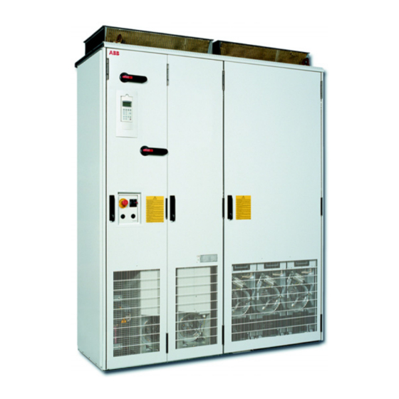
- Page 1 ACS800 Rittal TS 8 Cabinet Installation ACS800-04 and ACS800-04M Drive Modules (45 to 560 kW) ACS800-U4 Drives (60 to 600 HP)
-
Page 2: Acs800 Single Drive Manuals
ACS800 Single Drive Manuals HARDWARE MANUALS (appropriate manual is included in the delivery) ACS800-01/U1 Hardware Manual 0.55 to 110 kW (0.75 to 150 HP) 3AFE64382101 (English) ACS800-01/U1 Marine Supplement 3AFE64291275 (English) ACS800-02/U2 Hardware Manual 90 to 500 kW (125 to 600 HP) 3AFE64567373 (English) ACS800-11/U11 Hardware Manual 5.5 to110 kW (7.5 to 125 HP) - Page 3 ACS800-04 and ACS800-04M Drive Modules 45 to 560 kW ACS800-U4 Drive Modules 60 to 600 HP Rittal TS 8 Cabinet Installation 3AFE68372330 Rev A EN EFFECTIVE: 1.2.2005 2005 ABB Oy. All Rights Reserved.
-
Page 5: Table Of Contents
ACS800 Single Drive Manuals ........ - Page 6 ACS800-04M parts ........
-
Page 7: About This Manual
The manual is written for readers worldwide. Both SI and imperial units are shown. Safety WARNING! Follow the safety instructions given in ACS800-04/04M/U4 Hardware Manual [3AFE64671006 (English)] when installing, operating and servicing the drive. If ignored, physical injury or death may follow, or damage may occur to the drive, motor or driven equipment. -
Page 8: Other Related Manuals
/ Drives / Document library. Component lists ACS800-04M and Rittal parts used in the installation examples are listed in the manual. A list of other components, such as the contactor, switch fuse etc., is included in Modules Engineering Tool on www.abb.com... -
Page 9: Categorization According To The Frame Size
Note: The installation must always be designed and made according to applicable local laws and regulations. ABB does not assume any liability whatsoever for any installation which breaches the local laws and/or other regulations. About this manual... - Page 10 About this manual...
-
Page 11: Drive Module Of Frame Size R7 With Bottom Exit
ACS800-04M parts The following ACS800-04M parts are used in the installation: • drive module of type ACS800-04M-xxxx+B060+E202+H352+J400+J410. For descriptions of the plus codes, refer to ACS800-04/04M/U4 Cabinet Installation [3AFE68360323 (English)], chapter The ACS800-04/U4 and ACS800-04M: Type code. Drive module of frame size R7 with bottom exit... -
Page 12: Additional Parts To Be Provided By The Installer
EMC power cable lead- throughs Additional parts to be provided by the installer The following parts, in addition to the Rittal and ACS800-04M parts listed above, are needed in the installation: • air baffle, see page 17. • EMC screen, see page 16. -
Page 13: Layout Of The Installation
Layout of the installation This photo shows the final installation with component placing dimensions in millimetres and (inches). Support rail PS 4944.000 Note: A mirrored layout is advantageous for Air baffle Gasket strip Contactor servicing the drive module. 64331116 Punched section TS 8612.160 (600 mm) Side mounting plate... -
Page 14: Installation Steps
Installation steps Step Instruction Photo Fasten the base plates and lead- Left side view of the installation without side panel and EMC screen through plates to the enclosure frame. See also section Cable lead-through plates on page BACK FRONT Fasten the punched sections for the side mounting plate fastening Punched section TS 8612.160 to the vertical profiles of the... - Page 15 Step Instruction Photo Assemble the top entry clear plastic busbar shroud. Connect the laminated copper bars to the input terminals of the drive module. Fasten the top entry clear plastic busbar shroud to the drive module. Remove the protective film. Step drill lead-throughs for the busbars.
- Page 16 Step Instruction Photo Fasten the EMC screen and clear plastic shroud to the drive module. Clear plastic shroud (included in ACS800-04M bottom exit shroud kit +B060) 470 (18.50) 215 (8.46) 252 (9.92) Note: Remove the protective film from the shroud surfaces.
- Page 17 Step Instruction Photo Fasten the air baffle to the fastening points of the drive module and to the support rail with screws. The air baffle is needed for preventing hot air from entering the cool area of the cabinet. Air baffle Cutting for door Cutting for...
- Page 18 Step Instruction Photo Fasten the roof plate: 1. Cut an opening to the roof wire mesh for the upper edge of the air baffle. Place the mesh on the top of the enclosure frame. 2. Fasten the enclosure roof plate above the mesh with four 50 mm spacers at the corners.
- Page 19 Step Instruction Photo Install the C-rails and clamps for cable strain relief. Fasten the PE busbar. The PE busbar is provided for grounding of the input cable shield and the motor cable shield if the PE terminal of the drive module is not used.
-
Page 20: Cable Lead-Through Plates
Cable lead-through plates EMC kit 64331116 contains the lead-throughs without the strain relief plates shown below. Recommended entry for control cables in first environment installations (360 degrees grounding between the conductive cushions) Note: Control cable lead-throughs with rubber grommets only may also be possible. -
Page 21: Fastening Of The Back Mounting Plate
The attachment in the lower left-hand side module corner is shown here. View of the enclosure ftame when the back mounting plate (without the drive module) is fastened ProE: White Currant / acs800-04-rittal_common.asm, _common_no_heat.asm Drive module of frame size R7 with bottom exit... -
Page 22: Fastening Of The Rdcu Drive Control Unit To The Side Mounting Plate
Fastening of the RDCU Drive Control Unit to the side mounting plate Self-adhesive See RDCU Drive Control Unit Hardware strain relief Manual [3AFE64636324 (English)]. For grounding of the control cable shields Drive module of frame size R7 with bottom exit... -
Page 23: What This Chapter Contains
Additional parts to be provided by the installer The following parts, in addition to the Rittal and ACS800-04M parts listed above, are needed in the installation: • for first environment installations: EMC screen mesh which allows cooling air flow from the cooling unit to the input cable part of the enclosure. -
Page 24: Moving, Unpacking And Assembling The Drive Module
• PE busbar of dimensions 70 mm × 50 mm ×10 mm, copper • contactor (optional) • auxiliary voltage transformer when a contactor is installed • supply disconnecting device and input cable fuses. See the ACS800-04/04M/U4 Hardware Manual [3AFE64671006 (English)] chapters Planning the electrical installation and Technical data. -
Page 25: Layout Of The Installation
Layout of the installation This photo shows the final installation with component placing dimensions in millimetres and (inches). Note: A mirrored layout is advantageous for servicing the drive module. Contactor Punched section TS 8612.160 (600 mm) Side mounting plate TS 8614.240 1100 mm ×... -
Page 26: Cooling Air Flow
Cooling air flow Front top air baffle Side air baffles Fastening points of the top air baffle Air baffles at the sides and front top of the drive module are needed for guiding the cooling air from the cooling unit into the drive module through its inlet grating. -
Page 27: Installation Steps
Installation steps Install the cooling unit according to the manufacturer’s instructions to the side panel of the drive enclosure: 1. Cut openings in the side panel of the enclosure for air input and output and power supply wiring of the cooling unit. 2. - Page 28 Install the components into the enclosure as described in chapter Drive module of frame size R7 with bottom exit with the following exceptions: • Install the enclosure roof plate directly onto the enclosure frame without spacers and a wire mesh (no air outlet through the roof). •...
-
Page 29: Drive Module Of Frame Size R8 And Rittal Cooling Unit
Drive module of frame size R8 and Rittal cooling unit The drive module must be installed in a flat position (i.e. the vertical busbars on the short side, +H360) in a 600 mm deep enclosure to allow the cooling air flow through the drive module. -
Page 30: Layout Example With Cooling Unit On The Door
Layout example with cooling unit on the door 1000 mm Front view without the door Note: The cooling View from above fan of the drive module can be replaced by removing the drive module from the enclosure. Door Input cables Output cables Drive module of frame size R8 and Rittal cooling unit... -
Page 31: Drive Module Of Frame Size R8
Drive module of frame size R8 What this chapter contains This chapter describes the installation of a drive module of frame size R8 into a 600 mm deep, 800 mm wide and 2000 mm high Rittal TS 8 enclosure. The installation is designed to comply with the limits of IEC/EN 61800-3 for immunity and emissions of electrical equipment in second environment (includes establishments connected to a network not supplying domestic premises). -
Page 32: Acs800-04M Parts
[3AFE68360323 (English)], chapter The ACS800-04/U4 and ACS800-04M: Type code. Additional parts to be provided by the installer The following parts, in addition to the Rittal and ACS800-04M parts listed above, are needed in the installation: • air baffle, see 37. -
Page 33: Layout Of The Installation
Layout of the installation This photo shows the final installation with component placing dimensions in millimetres and (inches). Contactor Support rail PS 4944.000 Note: A mirrored layout is Removed Auxiliary voltage Air baffle advantageous for servicing the support rail transformer drive module. -
Page 34: Installation Steps
Slide the drive module onto the in the TS 8806.500 pedestal, connect the internal enclosure) busbars and fasten the module to the pedestal as shown in Control cable lead- ACS800-04/04M/U4 Cabinet throughs Installation [3AFE68360323 (English)]. Input cable lead- throughs PE terminal... - Page 35 Step Instruction Photo Fasten the drive module by its top to the back punched section. Fasten the switch fuse to the enclosure frame. C-rail Connect the switch fuse to the 600 mm contactor with laminated copper DK 7828.060 bars. Connect laminated copper bars to the output of the contactor.
- Page 36 Step Instruction Photo Step drill lead-throughs in the top cover of the top entry clear plastic busbar shroud. Pass the laminated copper bars through the lead-throughs and the lower part of the shroud. Connect the laminated copper bars to the input terminals of the drive module. Fasten the top entry clear plastic busbar shroud to the drive module.
- Page 37 Step Instruction Photo Fasten the air baffle to the fastening points of the drive module and to the support rail with screws. Cutting for control wiring Cutting for laminated copper bars Fasten the baffle by its top to the support rail (PS 4944.000) which is fastened to the enclosure frame...
- Page 38 Step Instruction Photo Fasten the RDCU Drive Control Unit. See RDCU Drive Control Unit Hardware Manual Self-adhesive [3AFE64636324 (English)]. strain relief Fasten a terminal for grounding the control cable shields and self- adhesive strain reliefs. Terminal for grounding of the control cable shields Strain relief clamp...
- Page 39 Step Instruction Photo Fasten the back panel of the enclosure. Fasten the side panels of the enclosure. Fasten the roof plate: 1. Cut an opening to the roof wire mesh for the upper edge of the air baffle. Place the mesh on the top of the enclosure frame.
-
Page 40: View Of Base Plates And Cable Lead-Throughs Fastened
Step Instruction Photo Install the C-rails and clamps for cable strain relief. Fasten the PE busbar. The PE busbar is provided for grounding of the input cable shield and the motor cable shield if the PE terminal of the drive module is not used. -
Page 41: Fastening Of The Punched Sections
Fastening of the punched sections Fastening the drive pedestal to the enclosure frame Support rail PS 4396.000 600 mm Pedestal fastening clamp (another clamp at the back side) M8×20 combi screw 80 (3.15) 350 (13.78) Fastening of the back mounting plate Drive module of frame size R8... - Page 42 Drive module of frame size R8...
-
Page 43: Dimensional Drawings
Dimensional drawings of air baffles and EMC screens are also shown. The dimensions are given in millimetres. 1 mm = 0.03936996 in.. For other dimensional drawings, refer to ACS800-04/04M/U4 Cabinet Installation [3AFE68360323 (English)]. Dimensional drawings... -
Page 44: Frame Size R7
Frame size R7 68469091_1 Dimensional drawings... -
Page 45: Frame Size R8
Frame size R8 68469091_2 Dimensional drawings... -
Page 46: Air Baffles For The Enclosure With Drive Module Of Frame Size R7 And Rittal Cooling Unit
Air baffles for the enclosure with drive module of frame size R7 and Rittal cooling unit The air baffles of the layout on page are shown below. Air baffle at the front top of the drive module 68484901 A Dimensional drawings... -
Page 47: Air Baffle At The Right-Hand Side Of The Drive Module
Air baffle at the right-hand side of the drive module Dimensional drawings... - Page 48 Air baffle at the left-hand side of the drive module 68484910 A Dimensional drawings...
-
Page 49: Emc Screen For The Enclosure With Drive Module Of Frame Size R7
EMC screen for the enclosure with drive module of frame size R7 The EMC screen used in the installation on page is shown below. Dimensional drawings... -
Page 50: Emc Screen Mesh For The Enclosure With Drive Module Of Frame Size R7 And Rittal Cooling Unit
EMC screen mesh for the enclosure with drive module of frame size R7 and Rittal cooling unit The EMC screen mesh used in the installation on page is shown below. Dimensional drawings... - Page 52 ABB Oy ABB Inc. AC Drives Automation Technologies P.O. Box 184 Drives and Motors FI-00381 HELSINKI 16250 West Glendale Drive FINLAND New Berlin, WI 53151 Telephone +358 10 22 11 +358 10 22 22681 Telephone 262 785-3200 Internet http://www.abb.com 800-HELP-365...