
Related Manuals for Dell S4048


Summary of Contents for Dell S4048
- Page 1 Dell Networking S4048–Open Networking (ON) Getting Started Guide Regulatory Model: E13W Regulatory Type: E13W001...
-
Page 2: Notes, Cautions, And Warnings
WARNING: A WARNING indicates a potential for property damage, personal injury, or death. Copyright © 2014 Dell Inc. All rights reserved. This product is protected by U.S. and international copyright and intellectual property laws. Dell and the Dell logo are trademarks of Dell Inc. -
Page 3: About This Guide
For complete installation, configuration, and update information, refer to the following documents at www.dell.com/support: Table 1. S4048-ON Documents Information Documentation Hardware installation and power-up instructions Dell Networking S4048-Open Networking (ON) Installation Guide Configuration Dell Networking Configuration Guide for the S4048- Open Networking (ON) System... -
Page 4: Install The Hardware
CAUTION: Always wear an electrostatic discharge (ESD)-preventive wrist or heel ground strap when handling the S4048–ON and its components. As with all electrical devices of this type, take all necessary safety precautions to prevent injury when installing this system. ESD damage can occur if components are mishandled. -
Page 5: Rack Mounting Safety Considerations
You may either place the switch on a rack shelf or mount the switch directly into a 19" wide, EIA-310-E- compliant rack (four-post, two-post, or threaded methods). The Dell ReadyRails™ system is provided for 1U front-rack and two-post installations. The ReadyRails system includes two separately packaged rail assemblies and two rails that are shipped attached to the sides of the switch. -
Page 6: Installing The Dell Readyrails System
1U Tool-less Configuration (Four-Post Square Hole or Unthreaded Round Hole) To install the Dell ReadyRails system using the 1U tool-less configuration, follow these steps. With the ReadyRails flange ears facing outward, place one rail between the left and right vertical posts. - Page 7 Figure 2. Two-Post Flush-Mount Configuration Two-Post Center-Mount Configuration To install the Dell ReadyRails system using the two-post center-mount configuration, follow these steps. Slide the plunger bracket rearward until it clicks into place and secure the bracket to the front post flange with two user-supplied screws.
- Page 8 Figure 3. Two-Post Center-Mount Configuration Four-Post Threaded Configuration To install the Dell ReadyRails system using the four-post threaded configuration, follow these steps. For this configuration, remove the flange ear castings from each end of the ReadyRails assemblies. Use a Torx driver to remove the two screws from each flange ear and remove each casting. Refer to item 1 of the following figure.
- Page 9 Installing a 1U Front-Rack You must configure the rails that are attached to the system. Attach the switch rails (inner chassis members) to the S4048–ON system. Item 3 in the following illustration shows the detail for the front standoff with the locking tab.
- Page 10 Figure 5. Attaching the Switch Rails After you have installed both switch rails, line them up on the previously mounted Ready-Rails and slide the switch in until it is flush with front of rack. About 3 inches before you fully insert your system, the rail locking feature engages to keep the switch from inadvertently sliding out of the rack and falling.
-
Page 11: Attaching The Ground Cable (Optional)
The S4048–ON requires one M4x0.7 screw for attaching a ground cable to the chassis. To properly ground the chassis, Dell Networking recommends a 6 AWG one-hole lug, #10 hole size, 63" spacing. The one-hole lug must be a UL-recognized, crimp-type lug. -
Page 12: Important Points To Remember
• The S4048–ON supports AC power supplies with two air-flow directions (I/O to Utility and Utility to I/O). The S4048–ON does not support mixing PSU types. The fan airflow direction for the PSUs must be the same. CAUTION: DO NOT mix airflow directions. Both power supplies must use the same airflow direction (I/O to Utility or Utility to I/O). -
Page 13: Installing A Fan Module
Figure 8. Install the AC Power Supply Unit Switch slot Attach the power cables from the switch PSU to the external power source. NOTE: The system is powered-up as soon as you connect the power cord between the system and the power source. Repeat steps 1 through 3 for the second PSU. -
Page 14: Installing The Sfp+ And Qsfp+ Optics
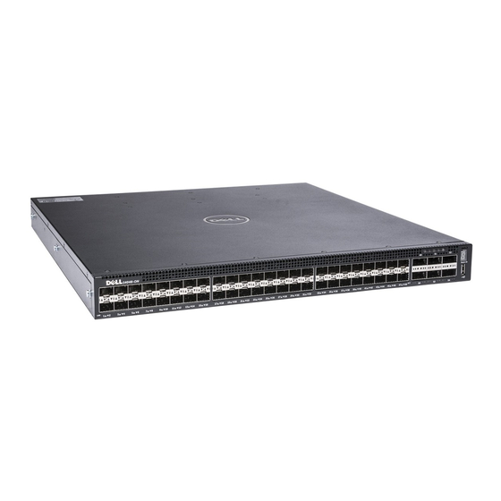
The S4048–ON has 48 small form-factor pluggable plus (SFP+) optical ports and six quad small form- factor pluggable plus (QSFP+) optical ports. For a list of supported optics, refer to the S4048–ON data sheet at www.dell.com or contact your Dell Networking representative. -
Page 15: After Installing The S4048-On
Connect the plug to each AC power connector. Make sure that the power cord is secure. As soon as the cable is connected between the S4048–ON and the power source, the switch is powered-up; there is no on/off switch. Fans The three fan modules and the power supplies are hot-swappable if you install a second (redundant) power supply. -
Page 16: Dell Networking Os
To initially configure the Dell Networking operating system (OS), use the following sections. NOTE: This chapter applies ONLY if you already have the Dell Networking OS installed on your system from the factory. If you are installing a third-party OS, refer to your third-party OS documentation. -
Page 17: Navigating Cli Modes
EXEC Privilege mode and the exit command which moves you up one command mode level. Accessing the Console The RS-232 console port is on the right-hand side of the S4048–ON system as you face the PSU side of the chassis, as shown in the following illustration. -
Page 18: Default Configuration
Signal Default Configuration When you install the Dell Networking OS onto your S4048–ON system, it is not configured when you power up for the first time (except for the default host name, which is Dell). You must configure the system using the CLI. -
Page 19: Configuring A Host Name
INTERFACE mode no shutdown Configuring the Management Route Define a path from the S4048–ON to the network from which you are accessing the S4048–ON remotely. Management routes are separate from IP routes and are used to manage the S4048–ON through the management port. -
Page 20: Configuring The Enable Password
(DES)-encryption method. • enable secret — stores the password in the running/startup configuration using a stronger, MD5- encryption method. Dell Networking recommends using the enable secret password. • Create a password to access EXEC Privilege mode. CONFIGURATION mode enable [password | secret] [level level] [encryption-type] password Creating a Port-based VLAN The default VLAN (VLAN 1) is part of the system startup configuration and does not require configuration. - Page 21 VLAN ID to the Default VLAN, use the default vlan-id vlan-id command from the configuration mode. • Access INTERFACE VLAN mode of the VLAN to which you want to assign the IP address then configure an IP addresses and mask on the interface. INTERFACE mode ip address ip-address mask [secondary] Dell Networking OS...
-
Page 22: Connect The S4048-On To The Network
Connect the S4048–ON to the Network After you have completed the hardware installation and software configuration for the S4048–ON system, connect to your company network by following your company’s cabling requirements. Dell Networking OS... -
Page 23: Technical Specifications
Technical Specifications This chapter lists the S4048–ON specifications. NOTE: Operate the system at an ambient temperature not higher than 113°F (45°C). CAUTION: Lithium Battery Caution: To avoid the possibility of an explosion, always replace the battery correctly. NOTE: Replace the battery only with the same or an equivalent type. Dispose of the batteries according to the manufacturer's instructions.