Dell S4820T Installation Manual
Hide thumbs
Also See for S4820T:
- Manual (60 pages) ,
- Configuration manual (1178 pages) ,
- Configuration manual (1128 pages)

Related Manuals for Dell S4820T


Summary of Contents for Dell S4820T
- Page 1 Installing the S4820T System April 2014...
- Page 2 WARNING: A WARNING indicates a potential for property damage, personal injury, or death. Copyright © 2014 Dell Inc. All rights reserved. This product is protected by U.S. and international copyright and intellectual property laws. Dell ™...
-
Page 3: Table Of Contents
Contents 1 About this Guide......................5 ..................... 5 Information Symbols and Warnings ..........................6 Related Documents 2 The S4820T Switch....................7 ............................7 Introduction ............................8 Prerequisites ..............................9 Features ..........................9 Physical Dimensions ............................9 Chassis Ports ........................9 Determine System Status ............................ - Page 4 7 Supply Power and Power Up the System............37 8 Connecting the Stacking Ports (Optional)............39 ......................39 Important Points to Remember .....................40 Connecting Two S4820T Systems ....................41 Connecting Three S4820T Systems ........................42 Hot-Swap Units in a Stack 9 Console Ports......................45 ..................
-
Page 5: About This Guide
After you have completed the hardware installation and powered up the S4820T refer to the FTOS Configuration Guide for the S4820T System for software configuration information. For command line interface (CLI) information, refer to the FTOS Command Line Reference Guide for the S4820T System. -
Page 6: Related Documents
Related Documents This document provides detailed hardware installation and power-up instructions to get new systems up and running and ready for configuration. For more information about the S4820T system, refer to the following documents: Table 1. S4820T Documents Information Documentation... -
Page 7: The S4820T Switch
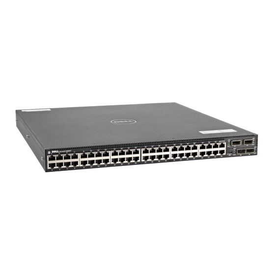
The S4820T system is a top-of-rack (ToR) switch/router product for copper connections to 10Gbps servers and 40Gbps optical uplinks to the 40Gbps switching fabric in the core. The S4820T has 48 ports of RJ-45 10GBase-T and four ports of 40Gbps with features and functions similar to the S4810 product. -
Page 8: Prerequisites
By providing increased 40GbE bandwidth for device interconnection in a shared network storage environment (with the possibility of splitting 40GbE quad small form-factor pluggable plus (QSFP+) uplinks into four 10GbE SFP+ or RJ-45 connections), the S4820T switch is perfectly positioned to help transition a data center with multiple speed requirements. -
Page 9: Features
One universal serial bus port (USB Type-A) Determine System Status You can view S4820T status information in several ways, including light emitting diodes (LEDs) and boot menu options. You can also view status information through the command line interface (CLI) show commands and with simple network management protocol (SNMP) traps. -
Page 10: Led Displays
Guide for the S4820T System. LED Displays As shown in the following figures, the S4820T includes LED displays on the front and back of the chassis. The tables provide a detailed description of each LED’s meaning. Figure 3. Port LEDs... - Page 11 Activity LED • Off –— No Link • Blinking green –— Transmit/Receive is active Table 5. OOB Ethernet Port LEDs Feature LED Color/Display Link LED • Off –— No Link • Solid green –— Link on 1Gbps speed The S4820T Switch...
-
Page 12: Orderable S4820T Components
You can order the following supported hardware components. • S4820T AC Normal Airflow: 48 port 10G RJ-45 ports with 4 QSFP+ 40G ports, 1 AC power supply and 2 fan subsystems (airflow from I/O side to power supply side) •... -
Page 13: Site Preparations
For S4820T specifications, refer to Technical Specifications. NOTE: Install the S4820T system into a rack or cabinet before installing any optional components. Site Selection Install Dell Networking equipment in restricted access areas. A restricted access area is one in which access can only be gained by service personnel by using a special tool, lock, key or other means of security and access is controlled by the authority responsible for the location. -
Page 14: Rack Mounting
Reversed — airflow is from the power supply to the I/O panel For proper ventilation, position the S4820T in an equipment rack (or cabinet) with a minimum of five inches (12.7cm) of clearance around the exhaust vents. When you install two S4820T systems near each other, position the two chassis at least five inches (12.7cm) apart to permit proper airflow. -
Page 15: Storing Components
WARNING: Electrostatic discharge (ESD) damage can occur when components are mishandled. Always wear an ESD-preventive wrist or heel ground strap when handling the S4820T and its accessories. After you remove the original packaging, place the S4820T and its components on an antistatic surface. -
Page 17: Install The Hardware
The S4820T and its accessories are shipped in multiple boxes. Before unpacking the switch, inspect the container and immediately report any evidence of damage. Verify that you have received your ordered items. For example, if you order one S4820T switch, the following items are included. -
Page 18: Install The Chassis
To install the S4820T system, Dell Networking recommends completing the installation procedures in the order presented in this document. You can install the S4820T switch on a rack shelf or mount it directly into a 19–inch wide, EIA-310-E- compliant rack (four-post, two-post, or threaded methods). Dell Networking provides the Dell ReadyRails™... -
Page 19: Install The Dell Readyrails System
NOTE: The illustrations in this document are not intended to represent a specific switch. Install the Dell ReadyRails System Dell Networking provides the ReadyRails rack mounting system so you can easily configure a rack to install the S4820T switch. You can install the ReadyRails system using the 1U tool-less method or one of three possible 1U tooled methods (two-post flush mount, two-post center mount, or four-post threaded). -
Page 20: Installing Readyrails - Tool-Less Method
Installing ReadyRails — Tool-less Method Use this installation method for four-post square hole or unthreaded round hole. With the ReadyRails flange ears facing outward, place one rail between the left and right vertical posts. Align and seat the rear flange rail pegs in the rear vertical post flange. In the following figure, item 3 and its extraction shows how the pegs appear in both the square and unthreaded round holes. -
Page 21: Installing Readyrails - Two-Post Flush-Mount Configuration
Installing ReadyRails — Two-Post Flush-Mount Configuration For this configuration, remove the castings from the front of each ReadyRails assembly. Install the Hardware... - Page 22 NOTE: Retain the castings for future rack requirements. It is not necessary to remove the rear flange castings. Remove the castings from the front of each ReadyRails assembly, as shown in item 1 in the following figure. Remove the two screws from each front flange ear (on the switch side of the rail) with a Torx driver.
-
Page 23: Installing Readyrails - Two-Post Center-Mount Configuration
Installing ReadyRails — Two-Post Center-Mount Configuration Slide the plunger bracket rearward until it clicks into place and secure the bracket to the front post flange with two user-supplied screws, as shown in item 1 in the following figure. Figure 6. Two-post Center-mount Configuration Slide the back bracket towards the post and secure it to the post flange with two user-supplied screws, as shown in item 2 in the figure. - Page 24 NOTE: Retain the castings for future rack requirements. Remove the flange ear castings from each end of the ReadyRails assemblies. Remove the two screws from each flange ear, and remove each casting with a Torx driver, as shown in item 1 in the figure. For each rail, attach the front and rear flanges to the post flanges with two user-supplied screws at each end, as shown in items 2 and 3 in the following figure.
-
Page 25: Attaching Switch Rails To The Switch And Mounting The Chassis
Attach the switch rails (inner chassis members) to the S4820T switch, as shown in item 1 in the following figure. Item 2 in the figure shows the detail for the front standoff with the locking tab. -
Page 26: Installing The Sfp+ And Qsfp+ Optics
Installing the SFP+ and QSFP+ Optics The S4820T has four quad small form-factor pluggable plus (QSFP+) optical ports. For a list of supported optics, refer to the S4820T data sheet at http://dell.com or contact your Dell Networking representative. CAUTION: ESD damage can occur if the components are mishandled. Always wear an ESD- preventive wrist or heel ground strap when handling the S4820T and its components. -
Page 27: Important Points To Remember
Splitting QSFP+ Ports to SFP+ or RJ-45 Ports The S4820T supports splitting a single 40G QSFP port into four 10G SFP+ ports or four 10G RJ-45 using one of the supported breakout cables. For the system to recognize the port type change, enter the stack-unit portmode command. For... -
Page 29: Power Supplies
The S4820T supports AC and DC power supplies with two air-flow directions (I/O to Utility and Utility to I/O). The S4820T does not support mixing PSU types. That is, you cannot replace an AC PSU with a DC PSU and an AC-R PSU with a DC-R PSU. The fan airflow direction for both the PSUs must be the same. -
Page 30: Installing Ac Or Dc Power Supplies
• To view the log messages, use the show logging command. For more information, refer to the System Logs chapters of the FTOS Command Line Reference Guide for the S4820T System and FTOS Configuration Guide for the S4820T System. WARNING: Although the switch can run on one PSU, Dell Networking highly recommends using two PSUs for full redundancy and proper cooling. -
Page 31: Replacing An Ac Or Dc Power Supply
Technical Support. NOTE: If you use a single PSU, you must install a blank plate in the other PSU slot. Dell Networking recommends using power supply 1 (PSU1) as the blank plate slot. Disconnect the power cable from the PSU. - Page 32 Refer to the figure. Insert the DC power connector into the power socket of the S4820T DC PSU. Make sure that you feel the connector pins firmly seat and you hear the click of the power connector’s left and right levered clamps lock into place.
- Page 33 NOTE: To remove the power connector from an S4820T DC PSU, squeeze together the levers on both sides of the connector. Doing so disengages the power connector’s clamps. While continuing to squeeze, pull the power connector from the DC PSU socket.
-
Page 35: Install Fans
Install Fans The S4820T comes from the factory with one power supply unit (PSU) and two fan modules installed in the chassis, as shown in the following figure. The fan modules and the integrated fan-power supply are hot-swappable. Figure 11. S4820T Fan Modules... -
Page 36: Installing A Fan Module
Tighten the securing screws on the sides of the fan module. To view the log messages, use the show logging command. For more information, refer to the System Logs chapters of the FTOS Command Line Reference Guide for the S4820T System and FTOS Configuration Guide for the S4820T System. -
Page 37: Supply Power And Power Up The System
Supply Power and Power Up the System Supply power to the S4820T after the chassis is mounted in a rack or cabinet. Dell Networking recommends re-inspecting your system prior to powering up. Verify that: • The equipment is properly secured to the rack. -
Page 39: Connecting The Stacking Ports (Optional)
Connecting the Stacking Ports (Optional) Before you make your stacking port connections, rack-mount the systems or insert them into a cabinet. NOTE: You can stack up to six S4820T switches. You cannot stack the S4820T system with other S- Series systems. -
Page 40: Connecting Two S4820T Systems
You can connect the systems while they are powered down or up. Stacking ports are bi-directional. The S4820T supports stacking in either a ring or a cascade topology, as shown in the following figure. To provide redundant connectivity, Dell Networking recommends using the ring topology when stacking... -
Page 41: Connecting Three S4820T Systems
You can use any of the RJ-45 or QSFP+ ports for stacking, provided you configure ports as stacking ports. To connect two S4820T systems in a ring, as shown in the figure, start with the S4820T at the bottom of the stack and follow these steps: NOTE: The port numbers in the following procedure are examples only. -
Page 42: Hot-Swap Units In A Stack
You can use any of the RJ-45 or QSFP+ ports for stacking, provided you configure ports as stacking ports. To connect three S4820T systems in a ring, as shown in the figure, start with the S4820T at the bottom of the stack and follow these steps: NOTE: The port numbers in the following procedure are examples only. - Page 43 For more information about removing a unit from a stack and other stacking commands, refer to the Stacking chapter in the FTOS Configuration Guide for the S4820T System and the Stacking Commands chapter in the FTOS Command Line Reference Guide for the S4820T System.
-
Page 45: Console Ports
Console Ports You can access the S4820T directly through the console port at the input/output (I/O) side of the system. Accessing the RJ-45 Console Port (RS-232) The RS-232/RJ-45 console port is labeled on the PSU-side of the S8420T chassis (the I/O side), as shown in the following figure. -
Page 46: Default Configuration
Default Configuration A version of FTOS is preloaded onto the S4820T; however, the system is not configured when you power up for the first time (except for the default host name, which is FTOS). You must configure the system using the CLI. -
Page 47: Technical Specifications
CAUTION: Lithium Battery Caution: There is a danger of explosion if the battery is incorrectly replaced. NOTE: Replace the battery only with same or equivalent type. Dispose of the batteries according to the manufacturer's instructions. Table 6. S4820T Chassis Physical Design Parameter Specifications Height 1.71 inches (43.5 mm) -
Page 48: Ieee Standards
Parameter Specifications Reliability MTBF 355,178 hours NOTE: The table below represents the DC PSU’s capabilities and does not represent S4820T operation. The power supply operates within all specified limits over the following input voltage range. Table 9. DC Input Specification... - Page 49 • Dell Networking (PVST+) • MTU (12,000 bytes) Technical Specifications...
-
Page 51: Agency Compliance
Properly shielded and grounded cables and connectors must be used in order to meet FCC emission limits. Dell Networking is not responsible for any radio or television interference caused by using other than recommended cables and connectors or by unauthorized changes or modifications in the equipment. -
Page 52: Canadian Department Of Communication Statement
This product is in conformity with the protection requirements of EU Council Directive 2004/108/EC on the approximation of the laws of the Member States relating to electromagnetic compatibility. Dell Networking cannot accept responsibility for any failure to satisfy the protection requirements resulting from a nonrecommended modification of this product, including the fitting of non-Dell option cards. -
Page 53: Korean Certification Of Compliance
WARNING: Use the AC power cords with Dell Networking equipment only. Do not use Dell Networking AC power cords with any unauthorized hardware. This is Class A product based on the standard of the Voluntary Control Council For Interference by Information Technology Equipment (VCCI). -
Page 54: Electromagnetic Compatibility (Emc)
EN 61000-4-6 Low Frequency Conducted Immunity Product Recycling and Disposal You must recycle or discard this system according to applicable local and national regulations. Dell Networking encourages owners of information technology (IT) equipment to responsibly recycle their equipment when it is no longer needed. Dell Networking offers various product return programs and services in several countries to assist equipment owners in recycling their IT products. - Page 55 EEE on the environment and human health due to the potential presence of hazardous substances in EEE. Dell Networking products, which fall within the scope of the WEEE, are labeled with the crossed-out wheelie-bin symbol, as shown above, as required by WEEE.
-
Page 57: Technical Support
Contacting the Technical Assistance Center The iSupport Website iSupport provides a range of documents and tools to assist you with effectively using Dell Networking equipment and mitigating the impact of network outages. Through iSupport you can obtain technical information regarding Dell Networking products, access to software upgrades and patches, and open and manage your Tech Support cases. - Page 58 Technical Documentation Log in to iSupport and select the Documents tab. You can access this page without logging in using the Documentation link on the iSupport page. Contact Information E-mail: Dell- [email protected] Web: http://www.support.dell.com/ Telephone: • US and Canada: 1-866-516-3115 •...
-
Page 59: Requesting A Hardware Replacement
Using the Create Service Request form on the iSupport page (refer to Contacting the Technical Assistance Center). b. Contacting Dell Networking directly by E-mail or by phone (refer to Contacting the Technical Assistance Center). Provide the following information when using E-mail or phone: •...