Dell S4100–ON Series Installation Manual
Hide thumbs
Also See for S4100–ON Series:
- Setup manual (21 pages) ,
- Installation manual (48 pages) ,
- Installation manual (49 pages)
Table of Contents
Table of Contents

Related Manuals for Dell S4100–ON Series


Summary of Contents for Dell S4100–ON Series
- Page 1 Installation Guide for the S4100–ON Series: S4128F-ON and S4148F-ON July 2017...
- Page 2 A WARNING indicates a potential for property damage, personal injury, or death. Copyright © 2017 Dell Inc. or its subsidiaries. All rights reserved. Dell, EMC, and other trademarks are trademarks of Dell Inc. or its subsidiaries. Other trademarks may be trademarks of their respective owners.
-
Page 3: Table Of Contents
Contents 1 About this guide............................. 5 Related documents................................5 Information symbols................................5 2 S4100–ON Series switch..........................7 Introduction..................................7 Features....................................9 Physical dimensions................................9 System status..................................9 LED display..................................9 LED behavior................................10 Prerequisites..................................13 S4100–ON Series configurations............................14 Luggage tag..................................15 3 Site preparations............................16 Site selection.................................. - Page 4 Safety standards and compliance agency certifications..................... 44 Electromagnetic compatibility (EMC)........................... 44 Emissions..................................44 Immunity..................................45 Product recycling and disposal............................45 Waste Electrical and Electronic Equipment (WEEE) directive for recovery, recycle, and reuse of IT and telecommunications products..........................45 9 Dell EMC support............................47 Contents...
-
Page 5: About This Guide
Dell Open Networking Hardware Diagnostic Guide • Dell EMC S4100–ON Series Release Notes NOTE: For the most recent documentation, visit Dell EMC support: www.dell.com/support. Information symbols This book uses the following information symbols: NOTE: The Note icon signals important operational information. - Page 6 WARNING: The Warning icon signals information about hardware handling that could result in injury. WARNING: The ESD Warning icon requires that you take electrostatic precautions when handling the device. About this guide...
-
Page 7: S4100-On Series Switch
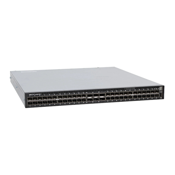
S4100–ON Series switch The following sections describe the Dell EMC S4100–ON Series (S4128F-ON and S4148F-ON) switch: Topics: • Introduction • Features • Physical dimensions • System status • LED display • Prerequisites • S4100–ON Series configurations • Luggage tag Introduction The S4100–ON Series (S4128F-ON and S4148F-ON) is a one rack unit (RU), full-featured fixed form-factor top-of-rack (ToR) - Page 8 Platform Description • 1 USB type-A port S4148F-ON • 48 fixed 10GbE SFP+ ports • 2 fixed 40GbE QSFP+ ports • 4 fixed 100GbE QSFP28 ports • seven-segment stacking indicator • 1 micro-USB-B console port • 1 USB type-A port Figure 2.
-
Page 9: Features
Figure 4. S4100–ON Series PSU-side view Four hot-swappable fan units Two hot-swappable PSUs with integrated fans Features The S4100–ON Series (S4128F-ON and S4148F-ON) offers the following features: • S4128F-ON: 28 fixed 10GbE SFP+ ports, 2 fixed 100GbE QSFP28 ports • S4148F-ON: 48 fixed 10GbE SFP+ ports, 2 fixed QSFP+ ports, 4 fixed 100GbE QSFP28 ports •... -
Page 10: Led Behavior
LED behavior The following S4100–ON Series switch LED behavior displays during open networking installation environment (ONIE) operations: Figure 5. S4128F-ON I/O-side LEDs QSFP28 port activity LEDs Link (left), activity (right) port LEDs Master LED System LED Power LED Fan LED Locator LED/System beacon Stack ID Figure 6. - Page 11 Figure 7. S4100-ON Series PSU-side LEDs Fan LED Link LED PSU LED Activity LED Table 3. S4100–ON Series LED behavior Description System Status/Health LED • Solid green—Normal operation • Blinking green—Booting • Solid yellow—Critical system error • Blinking yellow—Noncritical system error, fan failure, or power supply failure Power LED •...
- Page 12 Description • Blinking blue—Locator function is enabled 7-Segment LED for stacking • Off—No power • Solid green—Hex digit representing the stack unit ID Table 4. System management Ethernet port LEDs Description Link LED • Off—No link • Solid green—Link operating at a maximum speed— autonegotiated/forced or 1G port •...
-
Page 13: Prerequisites
Table 7. QSFP28 port LEDs: 4x25G or 4x10G mode Description Link/Activity LED • Off—No link • Solid green—Link operating at maximum speed—4x25G port • Flashing green—Link activity operating at maximum speed— 4x25G port • Solid yellow—Link operating at a lower speed—4x10G port •... -
Page 14: S4100-On Series Configurations
• S4100–ON Series (S4128F-ON or S4148F-ON) switch, or multiple switches, if stacking • AC country- and regional-specific cables to connect the AC power source to each of the switches' AC power supplies • Mounting brackets for rack installation, included • Screws for rack installation •... -
Page 15: Luggage Tag
Luggage tag The S4100–ON Series (S4128F-ON and S4148F-ON) switch has a pull-out tag, known as a luggage tag, on the PSU-side of the switch. The front of the luggage tag includes switch ID information. The back of the luggage tag includes a QRL that takes you to a How-To site where you watch videos about racking the switch, replacing components, configuring port channels, and so on. -
Page 16: Site Preparations
Storing components Site selection Install Dell EMC equipment in restricted access areas. A restricted access area is one where service personnel can only gain access using a special tool, lock, key, or other means of security. The authority responsible for the location controls access to the restricted area. -
Page 17: Rack Mounting
The ground path must be permanent. Switch ground Dell EMC recommends grounding your switch. Use the S4100–ON Series switch in a CBN. Fans and airflow The fans on the S4100–ON Series (S4128F-ON and S4148F-ON) support two airflow options: normal and reverse. -
Page 18: Storing Components
Storing components If you do not install your S4100–ON Series (S4128F-ON and S4148F-ON) swtich and components immediately, properly store the switch and all optional components following these guidelines: • Storage location temperature must remain constant. The storage range is from -40° to 149°F (-40° to 65°C). •... -
Page 19: S4100-On Series Installation
Two PSUs • Four fan units • Two country- and region-specific AC power cords • Dell S4100–ON Series Setup Guide • Safety and Regulatory Information • Warranty and Support Information Unpack Place the container on a clean, flat surface and cut all straps securing the container. -
Page 20: Rack Or Cabinet Installation
Inspect the product and accessories for damage. Rack or cabinet installation You may either place the switch on a rack shelf or mount the switch directly into a 19" wide, EIA-310- E-compliant rack. Rack mounting includes four-post, two-post, round threaded holes, or square holes. The ReadyRails system is provided for 1U front-rack and two-post installations. -
Page 21: 1U Tool-Less Mount Installation
Figure 9. Separate rails 1U Tool-less mount installation NOTE: For more installation instructions, see the installation labels attached to the rail assembly. Face the ReadyRails flange ears facing outward. Place one rail between the left and right vertical posts. Align and seat the back flange rail pegs in the back vertical post flange. -
Page 22: Two-Post Flush-Mount Installation
Figure 10. 1U tool-less installation Align and seat the front flange pegs in the holes on the front side of the vertical post. NOTE: Be sure that the rails click into place and are secure. Repeat this procedure for the second rail. To remove each rail, pull on the latch release button on each flange ear and unseat each rail. -
Page 23: Two-Post Center-Mount Installation
Figure 11. Two-post flush-mount installation Attach one rail to the front post flange with two user-supplied screws, item 2. Slide the plunger bracket forward against the vertical post and secure the plunger bracket to the post flange with two user-supplied screws, see item 3. -
Page 24: Four-Post Threaded Installation
Figure 12. Two-post center-mount installation Slide the back bracket towards the post. Secure it to the post flange with two user-supplied screws, items 2 and 3. Repeat this procedure for the second rail. Four-post threaded installation NOTE: For more installation instructions, see the installation labels attached to the rail assembly. Remove the latch castings from each end of the ReadyRails assemblies. -
Page 25: S4100-On Series Installation
Figure 13. Four-post threaded installation For each rail, attach the front and back flanges to the post flanges with two user-supplied screws at each end. S4100-ON Series installation You can mount the switch in the 1U front-rack two-post, flush or center configuration, or a four-post configuration. The following is an example of a front-rack configuration: For the 1U two-post configurations, slide the switch into the rails in the same manner as the four-post configurations. - Page 26 Figure 14. Switch rail attachment After you install both rails, line them up on the ReadyRails. Slide the switch in until it is flush with the front of rack. About three inches before you fully insert your switch, the rail locking feature engages to keep the switch from inadvertently sliding out and falling.
-
Page 27: Optics Installation
4 fixed QSFP28 optical ports For a list of supported optics, see the S4100–ON Series data sheet at www.dell.com/support or contact your Dell EMC representative. CAUTION: ESD damage can occur if components are mishandled. Always wear an ESD-preventive wrist or heel ground strap when handling the S4100–ON Series and its components. -
Page 28: Optics Removal
Dell EMC recommends reinspecting your switch before powering up. Verify the following: • The equipment is properly secured to the rack. Dell EMC recommends properly grounding the switch. • The ambient temperature around the unit, which may be higher than the room temperature, is within the limits specified for the S4100–... -
Page 29: Power Supplies
Power supplies The S4100–ON Series (S4128F-ON and S4148F-ON) switch ships with two AC or DC power supplies. The power supplies have two air-flow directions, normal and reverse. Normal is from the I/O-side to the PSU-side. Reverse is from the PSU-side to the I/O-side. The PSUs are field replaceable. -
Page 30: Psu Leds
NOTE: If you use a single PSU, install a blank plate in the other PSU slot. If you are only using one power supply, Dell EMC recommends installing the power supply in the first slot, PSU1. Install a blank plate in the second slot, PSU2. -
Page 31: Ac Or Dc Power Supply Replacement
NOTE: If you use a single PSU, install a blank plate in the other PSU slot. If you are only using one power supply, Dell EMC recommends installing the power supply in the first slot, PSU1. Install a blank plate in the second slot, PSU2. - Page 32 Figure 18. DC power supply and connector cable DC PSU power socket Cable connector with thumb screws Cable connector wires—black, green, and blue Wiring block DC power source wires—black, green, blue Strip 1/2 inches of insulation from each of the site’s DC power source wires, item 5. Insert each of the site’s DC power source’s bare wire lengths into the wiring block, matching the wire colors, items 3 and 4.
-
Page 33: Fans
Fans The S4100–ON Series (S4128F-ON and S4148F-ON) switch comes from the factory with two PSUs and four fan modules installed in the chassis. The fan modules and the power supplies are hot-swappable. NOTE: To run the switch, all slots must have operating fan units. If you do not install a module in each slot, the switch shuts down in one minute. -
Page 34: Fan Leds
Figure 20. S4100–ON Series fan modules installation Fan unit Fan module replacement To request a hardware replacement, see Dell EMC support. CAUTION: Complete the following steps within one minute or the switch temperature could rise above safe thresholds and the switch could shut down: Slide the fan module out of the bay. -
Page 35: Management Ports
Management ports Besides the 10/100/1000Base-T RJ-45 ports, the S4100–ON Series (S4128F-ON and S4148F-ON) switch provides several ports for management and storage. Topics: • RS-232 console port access • USB storage • USB-B console port access • Before you install an OS •... -
Page 36: Usb Storage
• No flow control USB storage USB storage does not automatically mount. The supported file system is FAT. To use USB storage, first mount the device using the following steps: Create a mount directory for the USB. ONIE:/ # mkdir /mnt/usb View the fixed disks using fdisk. -
Page 37: Before You Install An Os
Connect the USB-B end of cable into the USB-B console port on the S4100-ON Series switch. Power on the S4100-ON Series switch. Install the necessary USB device drivers. (To download the drivers, go to www.dell.com/support.) For assistance, contact Dell EMC Technical Support. -
Page 38: Onie Service Discovery
Open Networking Hardware Diagnostic Guide . NOTE: For more information, see the After you have securely installed and powered on the switch, to configure your switch, see your third-party ONIE-compatible OS or the Dell EMC OS documentation. ONIE service discovery ONIE attempts to locate the installer through several discovery methods, as shown. - Page 39 ONIE:/ # ping 10.11.8.12 PING 10.11.8.12 (10.11.8.12): 56 data bytes 64 bytes from 10.11.8.12: seq=0 ttl=62 time=1.357 ms 64 bytes from 10.11.8.12: seq=1 ttl=62 time=0.577 ms Management ports...
-
Page 40: Specifications
Specifications This section lists the S4100–ON Series (S4128F-ON and S4148F-ON) switch specifications. CAUTION: Operate the product at an ambient temperature not higher than 113°F—45°C. CAUTION: Lithium Battery Caution: There is a danger of explosion if the battery is incorrectly replaced. Replace only with same or equivalent type of battery. - Page 41 Table 14. Environmental parameters Parameter Specifications Operating temperature 5° to 40°C (50°F to 104°F) -5°C to 45°C (23°F to 113°F) short term Short term is
-
Page 42: Ieee Standards
Properly shielded and grounded cables and connectors must be used in order to meet FCC emission limits. Dell EMC is not responsible for any radio or television interference caused by using other than recommended cables and connectors or by unauthorized changes or modifications in the equipment. -
Page 43: Japan: Vcci Compliance For Class A Equipment
(VCCI). If this equipment is used in a domestic environment, radio disturbance may arise. When such trouble occurs, the user may be required to take corrective actions. WARNING: Use the AC power cords with Dell EMC equipment only. Do not use Dell EMC AC power cords with any unauthorized hardware. Figure 24. Japan: warning label... -
Page 44: Korean Certification Of Compliance
Korean certification of compliance Figure 25. Korean certification of compliance Figure 26. Korean package label Safety standards and compliance agency certifications • IEC 62368-1, 2nd Edition • CUS UL 60950-1, 2nd Edition • AS/NZS 60950 • CSA 60950-1-03, 2nd Edition •... -
Page 45: Immunity
You must recycle or discard this system according to applicable local and national regulations. Dell EMC encourages owners of information technology (IT) equipment to responsibly recycle their equipment when it is no longer needed. Dell EMC offers a variety of product return programs and services in several countries to assist equipment owners in recycling their IT products. - Page 46 Dell EMC products, which fall within the scope of the WEEE, are labeled with the crossed-out wheelie-bin symbol, as shown above, as required by WEEE. For information on Dell EMC product recycling offerings, see the WEEE Recycling instructions on the Support page. For more information, contact the Dell EMC Technical Assistance Center.
-
Page 47: Dell Emc Support
The Dell EMC support site provides integrated, secure access to these services. To access the Dell EMC support site, go to www.dell.com/support/. To display information in your language, scroll down to the bottom of the web page and select your country from the drop-down menu.