beautypg.com
Manuals
Brands
Carrier TRANSICOLD Manuals
Refrigerator
PrimeLINE 69NT40-571-001
Carrier TRANSICOLD PrimeLINE 69NT40-571-001 Manuals
Manuals and User Guides for Carrier TRANSICOLD PrimeLINE 69NT40-571-001. We have
1
Carrier TRANSICOLD PrimeLINE 69NT40-571-001 manual available for free PDF download: Operation And Service Manual
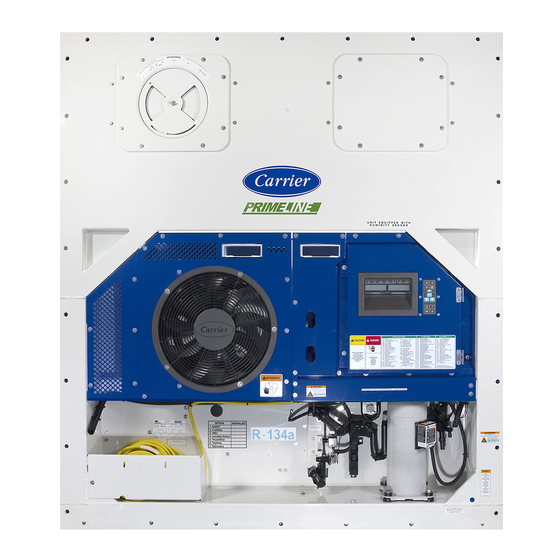
Carrier TRANSICOLD PrimeLINE 69NT40-571-001 Operation And Service Manual (186 pages)
Container Refrigeration Units
Brand:
Carrier TRANSICOLD
| Category:
Refrigerator
| Size: 6.13 MB
Table of Contents
Table of Contents
6
Troubleshooting
9
Figure 3.1 Refrigeration Unit - Front Section
23
Figure Number
23
Figure 3.2 Evaporator Section
24
Air-Cooled Condenser Section
25
Compressor Section
25
Figure 3.3 Compressor Section
25
Figure 3.4 Air Cooled Condenser Section
26
Figure 3.5 Brazed Plate Water-Cooled Condenser
27
Water-Cooled Condenser Section
27
Control Box Section
28
Figure 3.6 Control Box Section
28
Table Number
29
Electrical Data
29
Refrigeration System Data
29
Table 3-1 Refrigeration System Data
29
Table 3-2 Electrical Data
29
Abnormal Pressures
31
Safety and Protective Devices
31
Table 3-3 Safety and Protective Devices
31
Refrigeration Circuit
32
Standard Operation
32
Economized Operation
32
Electronic Expansion Valve (EEV)
32
Figure 3.7 Refrigeration Circuit Schematic - Standard Operation
33
Figure 3.8 Refrigeration Circuit Schematic - Economized Operation
34
Figure 3.9 Refrigeration Circuit Schematic - Water-Cooled Condenser (Brazed Plate)
35
Microprocessor
37
Temperature Control Microprocessor System
37
Control Module
37
Display Module and Keypad
37
Figure 4.1 Control Module
37
Figure 4.2 Display Module
38
Figure 4.3 Keypad
38
Table 4-1 Display Module Leds
38
Table 4-2 Keypad Function
38
Controller Software
39
Configuration Software (Cnf Variables)
39
Operational Software (CD Function Codes)
39
Modes of Operation
39
Start up - Compressor Phase Sequence
39
Start up - Compressor Bump Start
40
Perishable Mode (Temperature Control)
40
Perishable Pulldown Mode
40
Perishable Steady State Mode
40
Perishable Idle Mode (Air Circulation)
40
Perishable Heating Mode
40
Perishable Dehumidification
41
Figure 4.4 Controller Operation - Perishable Mode
41
Perishable Dehumidification - Bulb Mode
42
Perishable Economy Fan Mode
42
Perishable Mode Cooling - Sequence of Operation
43
Figure 4.5 Perishable Mode Cooling
43
Perishable Mode Heating - Sequence of Operation
44
Perishable Mode - Trim Heat
44
Frozen Mode (Temperature Control)
44
Frozen Steady State Mode
44
Figure 4.6 Perishable Mode Heating
44
Frozen Idle Mode
45
Frozen "Heat" Mode
45
Frozen Economy Mode
45
Frozen Mode Cooling - Sequence of Operation
45
Figure 4.7 Controller Operation - Frozen Mode
45
Defrost
46
Defrost Operation
46
Figure 4.8 Frozen Mode
46
Figure 4.9 Defrost
47
Defrost Related Settings
48
Protection Mode - Evaporator Fan Operation
48
Protection Mode - Failure Action
48
Protection Mode - Generator Protection
48
Protection Mode - Compressor High Temperature Protection
48
Protection Mode - Compressor Low Pressure Protection
48
Protection Mode - Perishable Mode System Pressure Regulation
48
Protection Mode - Condenser Fan Override
49
Quest
49
Controller Alarms
49
Figure 4.10 Alarm Troubleshooting Sequence
50
Pre-Trip Diagnostics
51
Datacorder
51
Table 4-3 Datacorder Function Code Assignments
52
Datacorder Configuration Software
53
Description
53
Sensor Configuration (Dcf02)
53
Table 4-4 Datacorder Configuration Variables
53
Table 4-5 Datacorder Standard Configurations
53
Logging Interval (Dcf03)
54
Alarm Configuration (Dcf07 - Dcf10)
55
Datacorder Power up
55
Sampling Type (Dcf05 & Dcf06)
55
Stored Temperature Display (Scrollback)
55
Thermistor Format (Dcf04)
55
Figure 4.11 Datacorder Configuration Screen
56
Pre-Trip Data Recording
56
USDA Cold Treatment
56
USDA Cold Treatment Procedure
56
Figure 4.12 Datacorder Probe Calibration Screen
57
Figure 4.13 Datacorder Probe Calibration Screen
57
Datacorder Communications
58
Figure 4.14 Datacorder Systems Tool Screen
58
ISO Trip Header
58
Controller Communications
59
Controller Wired Communications
59
Controller Wireless Communications
59
Figure 4.15 Dataline and Dataline Connect
59
Table 4-6 Wireless Settings Menu (Net) Options
60
Controller Configuration Variables
61
Table 4-7 Controller Configuration Variables
61
Controller Function Codes
62
Table 4-8 Controller Function Codes
62
4.10 Controller Alarm Indications
73
4.11 Controller Pre-Trip Test Codes
89
Table 4-9 Controller Pre-Trip Test Codes
89
Table 4-10 Datacorder Pre-Trip Result Records
95
Operation
97
Inspection
97
Connect Power
97
Connecting to 380/460 VAC Power
97
Connecting to 190/230 VAC Power
97
Adjust Fresh Air Makeup Vent
98
Upper Fresh Air Makeup Vent
98
Figure 5.1 Autotransformer
98
Vent Position Sensor
99
Everfresh Operation
99
Connect Water-Cooled Condenser
99
Figure 5.2 Upper Fresh Air Make up Flow Chart
99
Water-Cooled Condenser with Condenser Fan Switch
100
Water-Cooled Condenser with Water Pressure Switch
100
Starting and Stopping Instructions
100
Starting the Unit
100
Stopping the Unit
100
Start-Up Inspection
100
Physical Inspection
100
Check Controller Function Codes
100
Start Temperature Recorder in Datacorder
101
Complete Inspection
101
Pre-Trip Diagnosis
101
Starting a Pre-Trip
102
Figure 5.3 Tripwise Status in Datacorder
105
Figure 5.4 Generating Tripwise Summary Report
105
Figure 5.5 Tripwise Summary Report
106
Microprocessor Malfunction
114
6.10 no Evaporator Air Flow or Restricted Air Flow
114
6.12 Autotransformer Malfunction
114
6.14 Compressor Operating in Reverse
115
6.15 Abnormal Temperatures
115
6.16 Abnormal Currents
115
Service
117
7.1 Section Layout
117
7.2 Manifold Gauge Set
117
Figure 7.1 Manifold Gauge Set
117
Evacuating the Manifold Gauge Set
118
7.3 Service Connections
118
Figure 7.2 Manifold Gauge/Hose Set
118
7.4 Pump down the Unit
119
Figure 7.3 Service Valve
119
Automatic Pump down
120
7.5 Refrigerant Leak Checking
120
General
121
Preparation
121
Figure 7.4 Refrigeration System Service Connections
121
Evacuate and Dehydrate - Partial System
122
7.7 Refrigerant Charge
122
Checking the Refrigerant Charge
122
7.8 Converting to R-513A Refrigerant
123
7.9 Compressor
124
Removal and Replacement of Compressor
124
Figure 7.5 Compressor Kit
125
7.10 High Pressure Switch
126
Figure 7.6 High Pressure Switch Testing
126
Figure 7.7 Condenser Fan Position
129
Figure 7.8 Water-Cooled Condenser Cleaning - Forced Circulation
131
Figure 7.9 Water-Cooled Condenser Cleaning - Gravity Circulation
132
Figure 7.10 Heater Arrangement
133
Figure 7.11 Evaporator Fan Assembly
136
Figure 7.12 Access Panel Torque Pattern
137
Figure 7.13 Electronic Expansion Valve
139
Figure 7.14 Humidity Sensor
140
Figure 7.15 Access Panel Torque Sequence
140
Figure 7.16 Coil View of Economizer Solenoid Valve (ESV)
141
Figure 7.17 Economizer Expansion Valve
142
Figure 7.18 Adapter and O-Ring
143
Figure 7.19 View of Digital Unloader Valve (DUV) Assembly
144
Figure 7.20 Autotransformer
145
Table 7-1 Valve Override Control Displays for Cd41 "Selct
145
Controller Troubleshooting
146
Uploading a Software Configuration from a USB Drive
147
Downloading Datacorder Data to a USB Drive
147
Setting the Date and Time
147
Setting the Container ID
148
Removing and Installing a Controller
149
Battery Replacement
149
7.28 Temperature Sensor Service
150
Table 7-2 Sensor Resistance - AMBS, DTS, ETS, RRS, RTS, SRS, STS
152
Table 7-3 Sensor Resistance - Primeline CPDS
153
Figure 7.21 Supply Sensors - Cover Assembly and Sensors
154
Figure 7.22 Removing Front Access Panels
155
Figure 7.23 Removing Evaporator Motor
155
Figure 7.24 Return Sensors - Bracket
155
Figure 7.25 Return Sensors - Cutting Wire Ties
156
Figure 7.26 Dataline - Probe Calibration
156
Figure 7.27 Dataline - Calibrate Sensors Button
157
Figure 7.28 Dataline - Enter Service Center Information
157
Figure 7.29 Ice Bath
158
Figure 7.30 Dataline - Start Cal Button
158
Sensor Replacement
159
Figure 7.31 Dataline - Calibration Results
159
Figure 7.32 Sensor Types
160
Figure 7.33 Sensor and Cable Splice
160
Sensor RTS and RRS Reinstallation
161
Figure 7.34 Supply Sensor Positioning
161
Sensor DTS Reinstallation
162
Sensor, CPDS Reinstallation
162
Figure 7.35 Return Sensor Positioning
162
Figure 7.36 Evaporator Temperature Sensor Positioning
162
Vent Position Sensor (Vps)
163
7.30 Everfresh Service
163
Figure 7.37 Compressor Discharge Temperature Sensor
163
Table 7-4 R-134A Refrigerant Pressure Temperature Chart
164
Table 7-5 R-513A Refrigerant Pressure Temperature Chart
167
Table 7-6 Recommended Bolt Torque Values (Dry, Non-Lubricated for 18-8 Stainless Steel)
170
Figure 8.1 Legend - Standard Unit Configuration
171
Figure 8.2 Schematic Diagram
172
Figure 8.3 Unit Wiring Diagram (Sheet 1 of 2)
173
Figure 8.4 Unit Wiring Diagram (Sheet 2 of 2)
174
Eu Declaration of Conformity
177
Electrical Wiring Schematic and Diagrams
177
Wireless Certification
177
Index
181
Related Products
Carrier TRANSICOLD PrimeLINE 69NT40-571-199
Carrier TRANSICOLD PrimeLINE ONE 69NT40-575-001
Carrier TRANSICOLD PrimeLINE ONE 69NT40-575-199
Carrier TRANSICOLD 69NT40-511-200
Carrier TRANSICOLD 69NT40-511-299
Carrier TRANSICOLD 69NT40-489
Carrier TRANSICOLD 69NT40-541-200
Carrier TRANSICOLD 69NT40-541-299
Carrier TRANSICOLD PrimeLINE 69NT40-571
Carrier TRANSICOLD PrimeLINE 69NT40-571-100
Carrier TRANSICOLD Categories
Refrigerator
Automobile Accessories
Cooling boxes
Fan
Air Conditioner
More Carrier TRANSICOLD Manuals