
Related Manuals for Carrier TRANSICOLD PrimeLINE 69NT40-571-001


Summary of Contents for Carrier TRANSICOLD PrimeLINE 69NT40-571-001
- Page 1 Container Refrigeration OPERATIONS AND SERVICE MANUAL PrimeLINE 69NT40-571-001 to 199 PrimeLINE ONE 69NT40-575-001 to 199 Container Refrigeration Units T-372 Rev B...
- Page 3 OPERATIONS AND SERVICE MANUAL PrimeLINE 69NT40-571-000 to 199 PrimeLINE ONE 69NT40-575-000 to 199 Container Refrigeration Units © 2020 Carrier Corporation Printed in USA December 2020 ●...
- Page 5 TABLE OF CONTENTS PARAGRAPH NUMBER PAGE SAFETY SUMMARY ..............1–1 GENERAL SAFETY NOTICES .
-
Page 6: Table Of Contents
3.1.4 Compressor Section ............3–3 3.1.5 Air-Cooled Condenser Section . - Page 7 4.3.30 Quest ..............4–13 CONTROLLER ALARMS .
- Page 8 5.8.2 Displaying Pre-Trip Test Results ..........5–7 PROBE DIAGNOSTICS .
-
Page 9: Troubleshooting
7.10.1 Checking High Pressure Switch ..........7–10 7.10.2 Replacing High Pressure Switch . - Page 10 7.27.2 Controller Troubleshooting ..........7–30 7.27.3 Loading Controller Operational Software from a USB Drive .
- Page 11 LIST OF ILLUSTRATIONS FIGURE NUMBER Page Figure 3.1 Refrigeration Unit - Front Section ..........3–1 Figure 3.2 Evaporator Section .
- Page 12 Figure 7.14 Humidity Sensor ............. 7–24 Figure 7.15 Access Panel Torque Sequence .
- Page 13 LIST OF TABLES TABLE NUMBER Page Table 3–1 Refrigeration System Data ............3–7 Table 3–2 Electrical Data .
- Page 15 SECTION 1 SAFETY SUMMARY General Safety Notices Installation and servicing of refrigeration equipment can be hazardous due to system pressures and electrical components. Only trained and qualified service personnel should install, repair, or service refrigeration equipment. When working on refrigeration equipment, observe all potential Danger, Warning and Caution hazards, including those shown below and on hazard labels attached to the unit.
- Page 16 The statements listed below are applicable to the refrigeration unit and appear elsewhere in this manual. These recommended precautions must be understood and applied during operation and maintenance of the equipment covered herein. WARNING EXPLOSION HAZARD: Failure to follow this WARNING can result in death, serious personal injury and / or property damage.
- Page 17 WARNING Wear rubber gloves and wash the solution from the skin immediately if accidental contact occurs. Do not allow the solution to splash onto concrete. WARNING Always turn OFF the unit circuit breakers (CB-1 & CB-2) and disconnect main power supply before working on moving parts.
- Page 18 CAUTION Allowing the scroll compressor to operate in reverse for more than two minutes will result in internal compressor damage. Turn the Start-Stop switch OFF immediately. CAUTION To prevent trapping liquid refrigerant in the manifold gauge set, make sure set is brought to suction pressure before disconnecting.
- Page 19 Forklift pockets are provided for unit installation and removal. The Carrier Transicold PrimeLINE ONE™ models 69NT40-575-000 to 199 are units of lightweight aluminum frame construction, designed to be directly installed on-site onto a welded front wall of a container.
- Page 20 2.4.4 Compressor The unit is fitted with either an R-134a or an R-513A-ready scroll compressor equipped with suction and discharge service connections. To identify an R-513A-ready compressor in the field, a green dot is located on the top of the compressor on the DUV fitting.
- Page 21 2.5.15 Controller The controller is a Carrier Transicold Micro-Link 5 microprocessor. Refer to Section 4.1 for more information. Controllers will be factory-equipped with the latest version of operational software, but will NOT be configured for a specific model number and will need to be configured at the time of installation or sale.
- Page 22 2.5.17 EverFRESH EverFRESH™ is a controlled atmosphere option that is able control container atmosphere by supplying nitrogen and oxygen into the container space and simultaneously controlling levels of oxygen and carbon dioxide. This extends the produce ripening process, which increases shelf life and enables longer cargo routes for certain perishable commodities.
-
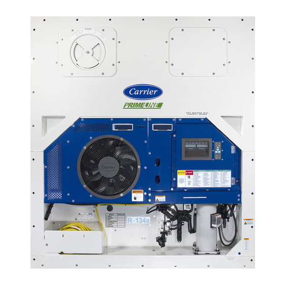
Page 23: Figure 3.1 Refrigeration Unit - Front Section
SECTION 3 DESCRIPTION General Description 3.1.1 Refrigeration Unit - Front Section Figure 3.1). The unit The unit is designed so that the majority of the components are accessible from the front (see model number, serial number and parts identification number can be found on the unit nameplate on the back wall of the condenser section. -
Page 24: Figure 3.2 Evaporator Section
3.1.2 Fresh Air Makeup Vent The function of the upper fresh air makeup vent is to provide ventilation for commodities that require fresh air circulation. A manually operated venting system is located in the upper left access panel. 3.1.3 Evaporator Section The evaporator section is shown in Figure 3.2. -
Page 25: Compressor Section
3.1.4 Compressor Section The compressor section (see Figure 3.3) includes the compressor, digital unloader valve (DUV), high pressure switch, discharge pressure transducer (DPT), evaporator pressure transducer (EPT) and the suction pressure transducer (SPT). The supply temperature sensor (STS) and supply recorder sensor (SRS) are located to the left of the compressor. -
Page 26: Figure 3.4 Air Cooled Condenser Section
Figure 3.4 Air Cooled Condenser Section 1) Micro Channel Heat Exchanger (MCHE) Coil 8) Receiver Moisture & Liquid Indicator* 2) Grille and Venturi Assembly 9) Fusible Plug 3) Condenser Fan 10) Filter Drier 4) Condenser Coil Cover 11) Economizer 5) Condenser Fan Motor 12) Economizer Solenoid Valve (ESV) 6) Receiver 13) Economizer Expansion Valve (EXV) -
Page 27: Water-Cooled Condenser Section
3.1.6 Water-Cooled Condenser Section The unit may contain a water-cooled condenser (WCC) installed as an option. When operating on the water-cooled condenser, the condenser fan is deactivated by a water pressure switch or condenser fan switch. Brazed Plate Water-Cooled Condenser The brazed plate water-cooled condenser section (see Figure 3.5) consists of the brazed plate water-cooled... -
Page 28: Control Box Section
3.1.7 Control Box Section The control box (see Figure 3.6) includes: the manual operation switches, circuit breaker (CB-1), compressor, fan and heater contactors, control power transformer, transformer AC line filter, fuses, keypad, display module, current sensor module, and the controller module. Figure 3.6 Control Box Section 1) Compressor Contactor (CH) 8) Current Sensor Module... -
Page 29: Refrigeration System Data
Refrigeration System Data Table 3–1 Refrigeration System Data Compressor / Motor Assembly Model Number ZMD26KVE-TFD-272 Weight (With Oil) 42.9 kg (95 lb) Approved Oil Uniqema Emkarate RL-32-3MAF Oil Charge 1774 ml (60 ounces) Electronic Expansion Valve Verify at - 18°C (0°F) 4.4 to 6.7°C (8 to 12°F) Superheat (Evaporator) container box temperature... - Page 30 Table 3–2 Electrical Data (Continued) Condenser Fan Motor Nominal Supply 380 VAC / 3 Phase / 50 Hz 460 VAC / 3 Phase / 60 Hz Full Load Amps .71 amps .72 amps Horsepower 0.21 hp 0.36 hp Rotations Per Minute 1450 rpm 1750 rpm Voltage and Frequency...
-
Page 31: Safety And Protective Devices
Table 3–2 Electrical Data (Continued) Humidity Sensor Orange wire Power Red wire Output Brown wire Ground Input voltage 5 VDC Output voltage 0 to 3.3 VDC Output voltage readings verses relative humidity (RH) percentage: 0.99 V 1.65 V 2.31 V 2.97 V Controller Setpoint Range... -
Page 32: Refrigeration Circuit
Refrigeration Circuit 3.5.1 Standard Operation Starting at the compressor, (see Figure 3.7) the suction gas is compressed to a higher pressure and temperature. The refrigerant gas flows through the discharge line and continues into the air-cooled condenser. When operating with the air-cooled condenser active, air flowing across the coil fins and tubes cools the gas to saturation temperature. -
Page 33: Figure 3.7 Refrigeration Circuit Schematic - Standard Operation
Figure 3.7 Refrigeration Circuit Schematic - Standard Operation Discharge Liquid Saturated Suction Vapor Mixture Vapor 1) Compressor 13) Economizer Expansion Valve (EXV) 2) Discharge Service Valve 14) Economizer Expansion Valve (EXV) Sensing Bulb 3) Discharge Pressure Transducer (DPT) 15) Economizer Connection 4) Condenser 16) Electronic Expansion Valve (EEV) 5) Receiver... -
Page 34: Figure 3.8 Refrigeration Circuit Schematic - Economized Operation
Figure 3.8 Refrigeration Circuit Schematic - Economized Operation Discharge Liquid Saturated Suction Vapor Mixture Vapor 1) Compressor 13) Economizer Expansion Valve (EXV) 2) Discharge Service Valve 14) Economizer Expansion Valve (EXV) Sensing Bulb 3) Discharge Pressure Transducer (DPT) 15) Economizer Connection 4) Condenser 16) Electronic Expansion Valve (EEV) 5) Receiver... -
Page 35: Figure 3.9 Refrigeration Circuit Schematic - Water-Cooled Condenser (Brazed Plate)
Figure 3.9 Refrigeration Circuit Schematic - Water-Cooled Condenser (Brazed Plate) Discharge Liquid Saturated Suction Vapor Mixture Vapor 1) Compressor 15) Economizer 2) Discharge Service Valve 16) Economizer Solenoid Valve (ESV) 3) Discharge Pressure Transducer (DPT) 17) Economizer Expansion Valve (EXV) 4) Condenser 18) Economizer Expansion Valve (EXV) Sensing Bulb 5) Water-Cooled Condenser... -
Page 37: Microprocessor
SECTION 4 MICROPROCESSOR Temperature Control Microprocessor System The temperature control Micro-Link 5 microprocessor system consists of a control module (controller), display module, keypad and interconnecting wiring. The controller houses the temperature control software and the Data- CORDER software. The temperature control software functions to operate the unit components as required to pro- vide the desired cargo temperature and humidity. -
Page 38: Figure 4.2 Display Module
Figure 4.2) consists of two 5-digit displays and seven indicator lights. Descriptions of the The display module (see indicator lights are provided in Table 4–1. The keypad (see Figure 4.3) consists of eleven push button switches that act as the user’s interface with the controller. Descriptions of the switch functions are provided in Table 4–2. -
Page 39: Controller Software
Controller Software The controller software is a custom designed program that is subdivided into configuration software and opera- tional software. The controller software performs the following functions: • Control supply or return air temperature to required limits, provide modulated refrigeration operation, econo- mized operation, unloaded operation, electric heat control, and defrost. -
Page 40: Start Up - Compressor Bump Start
4.3.2 Start Up - Compressor Bump Start At start up, the controller logic will initiate a compressor bump start procedure to clear liquid refrigerant from the compressor. If suction and discharge pressures have equalized, the compressor will perform three compressor bump starts. -
Page 41: Perishable Dehumidification
Figure 4.4 Controller Operation - Perishable Mode Perishable Mode Pull Down (Only Applicable to Perishable Mode) Controller Set Point ABOVE -10 C (+14 F), Controller Set Point ABOVE -10 C (+14 F), or -5 C (+23 F) optionally or -5 C (+23 F) optionally +2.5 C (+4.5 F) Cooling,... -
Page 42: Perishable Dehumidification - Bulb Mode
Two timers are activated during dehumidification to prevent rapid cycling and consequent contactor wear: 1. Heater debounce timer (three minutes) - The heater debounce timer is started whenever the heater contac- tor status is changed. The heater contactor remains energized (or de-energized) for at least three minutes even if the setpoint criteria are satisfied. -
Page 43: Perishable Mode Cooling - Sequence Of Operation
4.3.11 Perishable Mode Cooling - Sequence of Operation NOTE In Standard Perishable Mode, the evaporator motors run in high speed. In Economy Fan Mode, the fan speed is varied. a. When supply air temperature is above setpoint and decreasing, the unit will cool with the condenser fan motor (CF), compressor motor (CH), and evaporator fan motors (EF) energized, and the white COOL light illuminated. -
Page 44: Perishable Mode Heating - Sequence Of Operation
4.3.12 Perishable Mode Heating - Sequence of Operation a. If the supply air temperature decreases 0.5°C (0.9°F) below setpoint, the system enters the Heating Mode Figure 4.4). The controller closes contacts TH (see Figure 4.6) to allow power flow through the heat (see termination thermostat (HTT) to energize the heaters (HR). -
Page 45: Frozen Idle Mode
4.3.16 Frozen Idle Mode When temperature drops to setpoint minus 0.2°C (0.4°F) and the compressor has run for at least five minutes, the unit will transition to the Frozen Idle Mode. The compressor is turned off and the evaporator fans continue to run to circulate air throughout the container. -
Page 46: Defrost
c. When the return air temperature decreases to 0.2°C (0.4°F) below setpoint, contacts TC, TS and TN are opened to de-energize the compressor, economizer solenoid valve and condenser fan motor. The white COOL light is also de-energized. The electronic expansion valve (EEV) will close. d. -
Page 47: Figure 4.9 Defrost
When the defrost mode is in the active state, defrost can be initiated when any one of the following additional con- ditions become true: 1. Manually: While in the Defrost screen, when the Manual Defrost soft key is selected, if conditions will allow for a defrost, a manual defrost is initiated. -
Page 48: Defrost Related Settings
The EEV and DUV are independently operated by the microprocessor. Complete schematics and legends are located in Section 8. Defrost will terminate when the DTS reading rises above one of two model number configurable options selection, either an upper setting of 25.6°C (78°F) which is default or lower setting of 18°C (64°F). When the DTS reading rises to the configured setting, the de-icing operation is terminated. -
Page 49: Protection Mode - Condenser Fan Override
4.3.29 Protection Mode - Condenser Fan Override When CnF17 (Discharge Temperature Sensor) is set to “In” and CnF48 (Condenser Fan Switch Override) is set to “On”, the condenser fan switch override logic is activated. If condenser cooling water pressure is sufficient to open the water pressure switch (de-energizing the condenser fan) when water flow or pressure conditions are not main- taining discharge temperature, the logic will energize the condenser fan as follows: 1. -
Page 50: Figure 4.10 Alarm Troubleshooting Sequence
4. “CLEAr” is displayed if all alarms are inactive. Press the ENTER key to clear the alarm queue. The alarm list will clear and “-----” will be displayed. AL026 is active when none of the sensors are responding. Check the ME connector on the front of the controller. -
Page 51: Pre-Trip Diagnostics
4.6.1 Description Carrier Transicold “DataCORDER” software is integrated into the controller and serves to eliminate the tempera- ture recorder and paper chart. DataCORDER Software is subdivided into operational software, configuration soft- ware, and data memory. DataCORDER functions may be accessed by keypad selections and viewed on the display module. -
Page 52: Table 4-3 Datacorder Function Code Assignments
4.6.2 DataCORDER Operational Software The operational software reads and interprets inputs for use by the configuration software. The inputs are labeled function codes. Displaying DataCORDER Function Codes 1. Press the ALT. MODE key on the keypad. 2. Use the Arrow keys until “dC” is displayed, then press the ENTER key. 3. -
Page 53: Description
4.6.3 DataCORDER Configuration Software The configuration software controls the recording and alarm functions of the DataCORDER. Reprogramming to the factory-installed configuration is achieved via the USB flash drive menu with a flash drive installed. An ML5 soft- ware file or a compatible configuration database file must be on the USB flash drive in order to gain access to the menu. -
Page 54: Logging Interval (Dcf03)
The Generic Mode allows user selection of the network data points to be recorded. The user may select up to a total of eight data points for recording. Changing the configuration to generic and selecting which data points to record may be done using the Carrier Transicold Data Retrieval Program. A list of the data points available for recording follows. -
Page 55: Thermistor Format (Dcf04)
4.6.6 Thermistor Format (dCF04) The user may configure the format in which the thermistor readings are recorded. The short resolution is a 1 byte format and the long resolution is a 2 byte format. The short requires less memory and records temperature with variable resolutions depending on temperature range. -
Page 56: Pre-Trip Data Recording
4.6.11 Pre-Trip Data Recording The DataCORDER will record the initiation of a pre-trip test (refer to Section 4.5) and the results of each test Table 4– included in pre-trip. The data is time-stamped and may be extracted via the Data Retrieval program. See for a description of the data stored in the DataCORDER for each corresponding pre-trip test. -
Page 57: Figure 4.12 Datacorder Probe Calibration Screen
2. Calibrate the three USDA probes by ice bathing the probes and performing the calibration function with the DataLINE. This calibration procedure generates the probe offsets which are stored in the controller and applied to the USDA sensors for use in generating sensor type reports (see Figure 4.12). -
Page 58: Iso Trip Header
Figure 4.14. c. Using the System Tools screen in the DataLine software perform a “trip start.” See Figure 4.14 DataCORDER Systems Tool Screen 4.6.14 ISO Trip Header DataLINE provides the user with an interface to view / modify current settings of the ISO trip header through the ISO Trip Header screen. -
Page 59: Controller Communications
Figure 4.15 DataLINE and DataLINE Connect DataLINE software DataLINE Connect App Controller Communications 4.7.1 Controller Wired Communications Connect to the ML5 controller’s micro USB port with a flash drive or cable: • Use a flash drive to upload ML5 Controller Software with the ALT. MODE > USb menu. •... -
Page 60: Table 4-6 Wireless Settings Menu (Net) Options
Table 4–6 Wireless Settings Menu (nEt) Options Option Description EnbL Enable / Disable Wireless Connection (On/Off). If On, wireless mode shall be initialized according to the last saved wireless role. If Off, all existing wireless connections will be shut down and wireless is disabled. •... -
Page 61: Controller Configuration Variables
4.7.2.e Communicating with the Controller using DataLINE Connect (Android Device) This procedure explains how to open the DataLINE Connect application and connect it directly to a unit’s controller. 1. Open the DataLINE Connect application. 2. Open the WiFi Settings menu (or Settings menu). 3. -
Page 62: Controller Function Codes
Table 4–7 Controller Configuration Variables (Continued) Config Title Default Option CnF45 Low Humidity Enabled CnF46 Quench / Liquid Injection Valve Type nO=0=no nC=1=nc CnF47 Vent Position UP, LOW, CUStOM CnF49 OEM Reset Option 0-off,1-std, 2-spec,3-cust CnF50 Enhanced Bulb Mode Interface 0-out 1-in CnF51... - Page 63 Table 4–8 Controller Function Codes (Continued) Code Title Description Cd07 Main Power Voltage The main supply voltage is displayed. Cd08 Main Power Frequency The value of the main power frequency is displayed in Hertz. The frequency displayed will be halved if either fuse F1 or F2 is bad (alarm code AL021). Cd09 Ambient Temperature The ambient sensor reading is displayed.
- Page 64 Table 4–8 Controller Function Codes (Continued) Code Title Description Cd20 Config / Model Number This code indicates the dash number of the model for which the Controller is configured (i.e., if the unit is a 69NT40-551-100, the display will show “51100”). To display controller configuration database information, press the ENTER key.
- Page 65 Table 4–8 Controller Function Codes (Continued) Code Title Description Cd30 In-Range Tolerance The in-range tolerance will determine the temperature band around the setpoint which will be designated as in-range. For normal temperature control, control temperature is considered in range if it is within setpoint in-range Tolerance.
- Page 66 Table 4–8 Controller Function Codes (Continued) Code Title Description Cd36 Evaporator Fan Speed This is the desired evaporator fan speed for use during the bulb Dehumidification and Humidification Mode option. (Replaced by Cd48 if CnF50, Enhanced Bulb Mode, is active.) This code is enabled only if in the Dehumidification Mode (Cd33) and Bulb Mode (Cd35) has been set to “bulb.”...
- Page 67 Table 4–8 Controller Function Codes (Continued) Code Title Description Display Only Function - Cd44 is a display only function. Cd44 XtendFRESH Values | When XtendFRESH option enabled: EverFRESH Values Cd44 allows the user to view the following XtendFRESH values: CO setpoint, percentage, O setpoint, O...
- Page 68 Table 4–8 Controller Function Codes (Continued) Code Title Description Cd48 Dehumidification / Bulb Initially Cd48 will display current dehumidification-mode; bUlb - bulb cargo mode, Cargo Mode Parameter dEhUM - normal dehumidification, or OFF - off. This display is steady. Selection Press the ENTER key to take the interface down into a hierarchy of parameter selection menus (mode, setpoint, evaporator speed, DTT setting).
- Page 69 Table 4–8 Controller Function Codes (Continued) Code Title Description Cd50 QUEST Enable / ”OFF” = disabled. Disable ”On” = enabled. ”SEtPt” = suspended by setpoint too low. ”CAHUM” = suspended by CA or humidity control. ”ACt” = suspended by ACT active. ”FAIL”...
- Page 70 Table 4–8 Controller Function Codes (Continued) Code Title Description Cd53 Automatic Setpoint Automatic Setpoint Change (ASC) Mode: Change (ASC) Mode Cd53 increments of (1 day)_(1hr), Display: default “0_0 “ Parameter Selection “done” mm-dd this will be display is ASC has completed “ASC”...
- Page 71 Table 4–8 Controller Function Codes (Continued) Code Title Description Cd58 Water Pressure Switch Cd58 will display “CLOSE” if the WPS or CFS switch contacts are closed or if / Condenser Fan these options are not installed. “OPEn” is displayed when the WPS or CFS switch Switch State or contacts are open.
- Page 72 Table 4–8 Controller Function Codes (Continued) Code Title Description Cd65 TripWise If the function is off, display "OFF". If the function is on, display "ON". “-----” will be displayed if the TripWise option is not active for the current configuration. Press the ENTER key.
-
Page 73: 4.10 Controller Alarm Indications
4.10 Controller Alarm Indications There are three alarm categories: • AL0XX Refrigeration Critical Alarms • AL2XX Refrigeration Non-Critical Alarms • AL9XX Atmosphere Critical and Non-Critical Alarms AL003 Loss of Superheat Control Cause: Superheat has remained below 1.66°C (3°F) degrees for five minutes continuously while compressor running. - Page 74 AL020 Control Fuse (F3) Open Cause: Control power fuse (F3 or F4) is open. Component Check F3 fuse. Troubleshooting If fuse is open, check PA, PB, CH coils for short to ground. Corrective Action If short is found, replace the defective coil. Replace the fuse. Component Check F4 fuse.
- Page 75 AL024 Compressor IP Open Cause: Compressor internal protector (IP) is open. Component Compressor Troubleshooting Shut down unit disconnect power and check resistance of compressor windings at contactor T1-T2, T2-T3. Corrective Action Monitor unit, if alarm remains active or is repetitive replace the compressor at the next available opportunity.
- Page 76 AL028 Low Suction Pressure Component Suction Pressure Transducer (SPT) Troubleshooting Confirm accurate SPT pressure readings. See Manifold Gauge Set Section 7.2. Corrective Action Replace SPT if defective. Component Discharge Pressure Transducer (DPT) Troubleshooting Confirm accurate DPT pressure readings. See Manifold Gauge Set Section 7.2.
- Page 77 AL214 Phase Sequence Detect Fault Cause: Controller is unable to determine the correct phase relationship. Component N/A Troubleshooting Power cycle the unit. Corrective Action Resetting the unit may correct problem, monitor the unit. Component Wiring Troubleshooting Check unit wiring. Confirm pressure readings during start-up; suction pressure should decrease and discharge pressure should increase.
- Page 78 AL219 Discharge Temperature High Cause: Discharge temperature exceeds 135°C (275°F) for 10 minutes within the last hour. Component Restrictions in the refrigeration system. Troubleshooting Ensure the discharge service valve is fully open. Corrective Action Open the discharge service valve as needed. Troubleshooting Check the unit for air flow restrictions.
- Page 79 AL253 Battery Pack Fault Cause: Any of the USDA1, USDA2, or USDA3 probes have been detected AND the Backup Battery Test Result is Failure. Or, no Battery. Component Battery Troubleshooting Perform battery test in function code Cd19 to determine failure mode of battery.
- Page 80 AL259 Heat Termination Thermostat (HTT) Open Cause: Heat Termination Thermostat (HTT) is open. Component Heat Termination Thermostat (HTT) Troubleshooting Check resistance between CA21 and CA10. If 0 ohms, switch closed. if infinite (OL), switch open. Corrective Action Replace HTT if defective. See Sensor Replacement Section 7.28.
- Page 81 AL264 Discharge Temperature Sensor (CPDS) Fault Troubleshooting Test the CPDS. See Sensor Checkout Procedure, Section 7.28.2. Corrective Action Replace the CPDS if defective. See Sensor Replacement Section 7.28. AL265 Discharge Pressure Transducer (DPT) Fault Cause: Compressor Discharge Pressure Transducer (DPT) is out of range. Component Discharge Pressure Transducer (DPT) Troubleshooting Confirm accurate DPT pressure readings.
- Page 82 AL271 Return Recorder Sensor (RRS) Fault Cause: Return Recorder Sensor (RRS) is out of range. Component Return Recorder Sensor (RRS) Troubleshooting Perform pre-trip P5. Corrective Action If P5 passes, no further action is required. If P5 fails, replace the defective sensor as determined by P5.
- Page 83 AL286 RTC Battery Low Corrective Action If alarm stays active, replace battery. AL287 RTC Fault Cause: RTC time invalid. Component Real Time Clock Troubleshooting Power cycle. Reset clock. Verify it maintains correct time. Corrective Action Replace RTC Battery. Retest. AL289 Data Storage Fault Cause: Unable to store data in DataCorder.
- Page 84 AL910 Carbon Dioxide Sensor (CO2) Fault Cause: Triggered anytime the CO sensor reading is outside of the normal operation range, after an initial signal was detected. Action: Control O to setpoint. Controlling O may allow CO to increase. Replace sensor as soon as possible.
- Page 85 AL929 Loss of Atmospheric Control Component Water Drain Valve (WDV) Troubleshooting A closed or plugged WDV or filter housing could prevent any air from entering the container. P20-3 tests valve operation. Potential failure results: • MPT pressure fails to change when the valve is energized. Check for signs of blockage by removing the WDV housing and particu- late filter housings.
- Page 86 AL977 Membrane Pressure Transducer (MPT) Fault Cause: When the EverFRESH Air Compressor (EAC) is running and pressure is not between -5 psig and 200 psig or the EAC has been OFF for five minutes and pressure is not within the range of -5 psig and 5 psig.
- Page 87 AL980 Fresh Air Valve (EA) Fault Cause: When the system energizes the EverFRESH Air Valve (EA) solenoid and membrane pressure does not drop 40 psi, the alarm is triggered. The alarm triggers OFF when membrane pressure transducer (MPT) pressure drop is more than 40 psi when EA is opened. Component EverFRESH Air Valve (EA) Solenoid Troubleshooting Run a P20 test to verify mechanical and electrical performance of the solenoid.
- Page 88 AL996 Scrubber Rotation Fault Cause: Feedback from the Scrubber Motor to the controller is not sensed when the motor is turning. Component Scrubber Fuse Troubleshooting Check to see if Scrubber Fuse is blown. Replace Fuse if necessary. Component Scrubber Motor Troubleshooting Run Test Mode and verify scrubber bed is turning.
-
Page 89: 4.11 Controller Pre-Trip Test Codes
4.11 Controller Pre-Trip Test Codes Table 4–9 Controller Pre-Trip Test Codes NOTE: “Auto” or “Auto1” menu includes the: P0, P1, P2, P3, P4, P5, P6 and rSLts. “Auto2” menu includes P0, P1, P2, P3, P4, P5, P6, P7, P8, P9, P10 and rSLts. “Auto3” menu includes P0, P1, P2, P3, P4, P5, P6, P7 and P8. P0-0 Pre-Trip Initiated: Container identifier code, Cd18 Software Revision Number, Cd20... - Page 90 Table 4–9 Controller Pre-Trip Test Codes (Continued) P4 Tests - High Speed Evaporator Fans Current Draw: High speed evaporator fans are turned on, then off. Current draw must fall within specified range and measured current changes must exceed spec- ified ratios. No other system components will change state during this test. NOTE If unit configured for single evaporator fan operation and either AL11 or AL12 is active at the start of either test, then the test will fail immediately.
- Page 91 Table 4–9 Controller Pre-Trip Test Codes (Continued) P5-3 Evaporator Fan Direction Test With evaporator fan running on high speed, measure the temperature difference between the primary supply and primary return probes. Turn the heaters on for 60 seconds then measure the temperature difference between the primary supply and primary return probes for up to 120 additional seconds.
- Page 92 Table 4–9 Controller Pre-Trip Test Codes (Continued) P6-5 Compressor Leak Test Pre-trip P6-5 ensures that the compressor holds pressure. After compressor pump up and pump down, the compressor is turned off for 62 seconds. When suction side pressure holds (less than 8 psi rise) for 10 seconds, P6-5 passes, otherwise the Compressor Leak Test fails.
- Page 93 Table 4–9 Controller Pre-Trip Test Codes (Continued) P7-1 High Pressure Switch (HPS) If return temperature greater than -2.4°C, set setpoint to -5.0°C, else set Closing Test setpoint to -30°C. Restart unit according to normal startup logic. Run unit normally for 120 seconds. The test passes if the high pressure switch closes within 75 seconds after end of Test 7-0, else the test fails.
- Page 94 Table 4–9 Controller Pre-Trip Test Codes (Continued) P9-0 DTT Closed and Open Test During P9-0 the defrost temperature sensor (DTS) reading will be displayed on the left display. The right display will show the supply air temperature. The unit will run FULL COOL for 30 minutes maximum until the DTT is considered closed.
-
Page 95: Table 4-10 Datacorder Pre-Trip Result Records
Table 4–10 DataCORDER Pre-Trip Result Records Test Title Data Heater On Pass / Fail / Skip Result, Change in current for Phase A, B and C Heater Off Pass / Fail / Skip Result, Change in currents for Phase A, B and C Condenser Fan On Pass / Fail / Skip Result, Water pressure switch (WPS) - Open / Closed, Change in currents for Phase A, B and C... - Page 96 Table 4–10 DataCORDER Pre-Trip Result Records (Continued) Test Title Data High Pressure Switch Open Pass / Fail / Skip Result, STS, DPT or CPT (if equipped) Input values that component closes Perishable Mode Heat Test Pass / Fail / Skip Result, STS, time it takes to heat to 16°C (60°F) Perishable Mode Pulldown Test Pass / Fail / Skip Result, STS, time it takes to pull down to 0°C (32°F) Perishable Mode Maintain Test Pass / Fail / Skip Result, Averaged DataCORDER supply temperature (SRS) over last recording interval.
-
Page 97: Operation
SECTION 5 OPERATION Inspection WARNING Beware of unannounced starting of the evaporator and condenser fans. The unit may cycle the fans and compress or unexpectedly as control requirements dictate. 1. Check inside the unit for the following conditions: • Check channels or “T” bar floor for cleanliness. Channels must be free of debris for proper air circulation. •... -
Page 98: Adjust Fresh Air Makeup Vent
PROCEDURE: 1. Make sure the Start-Stop switch (ST), located on the control panel, is in “0” position (Off). 2. Make sure circuit breaker CB-1, located in the control box, and CB-2, located on the transformer, are both in “0” position (Off). 3. -
Page 99: Vent Position Sensor
Figure 5.2 Upper Fresh Air Make Up Flow Chart FLOW FLOW (CMH) 60HZ (CMH) 50HZ TBAR TBAR 1 1/2” 1 1/2” TBAR TBAR 2 5/8” 2 5/8” TBAR 3” TBAR 3” PERCENT OPEN PERCENT OPEN 5.3.2 Vent Position Sensor The vent position sensor (VPS) allows the user to determine the position of the fresh air vent via Cd45. This func- tion code is accessible via the CODE SELECT key. -
Page 100: Water-Cooled Condenser With Water Pressure Switch
5.5.1 Water-Cooled Condenser with Water Pressure Switch 1. Connect the water supply line to the inlet side of the condenser and the discharge line to the outlet side of the condenser (see Figure 3.5). 2. Maintain a flow rate of 11 to 26 liters per minute (3 to 7 gallons per minute). The water pressure switch will open to de-energize the condenser fan relay. -
Page 101: Start Temperature Recorder In Datacorder
5.7.3 Start Temperature Recorder in DataCORDER 1. Check and, if required, set the DataCORDER Configuration in accordance with desired recording parame- ter. See Section 4.6.4. 2. Enter a “Trip Start” with the following instructions: a. Press the ALT MODE key. b. -
Page 102: Starting A Pre-Trip
Prior to starting a pre-trip test, very the following: • Unit voltage (Cd07) is within tolerance • Unit amperage draw (Cd04, Cd05, Cd06) are within expected limits • All alarms are cleared and rectified. 5.8.1 Starting a Pre-Trip 1. Press the PRE-TRIP key to access the pre-trip test selection menu. “SELCt PrtrP” will be displayed. 2. - Page 103 5.8.2 Displaying Pre-Trip Test Results 1. Press the PRE-TRIP key to access the Pre-trip test selection menu. “SELCt PrtrP” will be displayed. 2. Press the Arrow keys until the message “P,” “rSLts” (Pre-trip results) is displayed. 3. Press the ENTER key. The results for all Pre-trip sub tests are available from this menu (i.e., 1-0, 1-1, etc). The results will be displayed as “PASS”...
- Page 104 5.10 TripWise (Option) TripWise is a new premium option available for PrimeLINE and PrimeLINE with Edge units. TripWise is software logic that runs during every voyage as often as possible to indicate whether a standard Pre-trip Inspection (PTI) is needed and skip unless necessary. The tests run in the background and are similar to those completed as part of the standard PTI selection, which includes the following: •...
-
Page 105: Figure 5.3 Tripwise Status In Datacorder
5.10.3 TripWise Status Event A TripWise status event will be recorded in the DataCORDER recorder when the PTI is selected. In the current DataLINE software release, the event will show the status of the unit. Figure 5.3 TripWise Status in DataCORDER In DataLINE, perform an all data download by selecting from the drop down menu “TripWise Summary”... -
Page 106: Figure 5.5 Tripwise Summary Report
This will generate the status / results in a DataLINE TripWise Summary Report as shown in the Figure below. Figure 5.5 TripWise Summary Report Status Results T-372 5–10... - Page 107 Automated Cold Treatment (ACT) in the Carrier Transicold unit is a method to simplify the task of completing cold treatment by automating the process of changing the setpoints. ACT is set up through function code Cd51. Refer to Function Code table in this manual for Cd51 menu processing and displays.
- Page 108 8. "SPnEW" is now displayed in the left display and the right will be flashing. Use the Arrow keys to select the desired setpoint after the cold treatment process has successfully completed and press the ENTER key. This would be the final temperature prior to the delivery of the cargo. COOL HEAT DEFROST...
- Page 109 5.12 Automatic Setpoint Change (ASC) Cd53 Automatic Setpoint Change (ASC) allows up to 6 setpoint changes to be pre-programmed over defined periods of time using Cd53. 1. Press the CODE SELECT key. 2. Use the Arrow keys to scroll to Cd53, then press the ENTER key. 3.
- Page 111 SECTION 6 TROUBLESHOOTING Condition Possible Cause Remedy / Reference Section Unit will not Start or Starts then Stops External power source OFF Turn on Start-Stop switch (ST) OFF or defective Check No power to unit Circuit breaker tripped or OFF Check Autotransformer not connected Section 5.2.2...
- Page 112 Condition Possible Cause Remedy / Reference Section Unit Runs but has Insufficient Cooling Abnormal pressures Section 6.7 Abnormal temperatures Section 6.15 Abnormal currents Section 6.16 Controller malfunction Section 6.9 Evaporator fan or motor defective Section 7.17 Refrigeration system Compressor service valves or liquid line shutoff valve Open valves completely partially closed Frost on coil...
- Page 113 Condition Possible Cause Remedy / Reference Section Manual defrost switch defective Replace Will not initiate defrost Keypad is defective Replace manually Defrost temperature sensor open Replace Initiates but relay (DR) drops Low line voltage Section 3.3 Heater contactor or coil defective Replace Initiates but does not defrost Heater(s) burned out...
-
Page 114: Microprocessor Malfunction
Condition Possible Cause Remedy / Reference Section Microprocessor Malfunction Incorrect software and/or controller configuration Check Defective sensor Section 7.28 Will not control Defective wiring Check Low refrigerant charge Section 7.3 6.10 No Evaporator Air Flow or Restricted Air Flow Section 6.6 Frost on coil Evaporator coil blocked Section 7.15... -
Page 115: 6.14 Compressor Operating In Reverse
Condition Possible Cause Remedy / Reference Section 6.13 Water-Cooled Condenser or Water Pressure Switch Dirty coil High discharge pressure Section 7.13 Non-condensibles Water pressure switch malfunction Check Condenser fan starts and stops Water supply interruption Check 6.14 Compressor Operating in Reverse NOTE The compressor may start in reverse for up to 10 seconds to determine correct phase rotation if required for phase detection. -
Page 117: Service
SECTION 7 SERVICE WARNING EXPLOSION HAZARD Failure to follow this WARNING can result in death, serious personal injury and / or property damage. Never use air or gas mixtures containing oxygen (O ) for leak testing or operating the product. Charge only with refrigerants R-134a or R-513A as specified for the unit model number: Refrigerant must conform to AHRI Standard 700 specification. -
Page 118: Evacuating The Manifold Gauge Set
A manifold gauge / hose set with self-sealing hoses (see Figure 7.2) is required for service of the models covered within this manual. The manifold gauge/hose set is available from Carrier Transicold (part number 07-00294-00, Figure 7.2). which includes items 1 through 6, NOTE It is recommended that the manifold gauge set be dedicated to specified refrigerant (R-134a or R-513A). -
Page 119: 7.4 Pump Down The Unit
With the valve stem midway between frontseat and backseat, both of the service valve connections are open to the access valve path. For example, the valve stem is first fully backseated when connecting a manifold gauge to mea- sure pressure. Then, the valve is opened 1/4 to 1/2 turn to measure the pressure. Figure 7.3 Service Valve Valve (Backseated) Valve (Frontseated) -
Page 120: Automatic Pump Down
CAUTION The scroll compressor achieves low suction pressure very quickly. Do not use the compressor to evacuate the system below 0 psig. Never operate the compressor with the suction or discharge service valves closed (frontseated). Internal damage will result from operating the compressor in a deep vacuum. -
Page 121: General
2. Essential tools to properly evacuate and dehydrate any system include a vacuum pump (8m3/hr = 5 cfm volume displacement) and an electronic vacuum gauge. The pump is available from Carrier Transicold, P/N 07-00176-11. The micron gauge is P/N 07-00414-00. -
Page 122: Evacuate And Dehydrate - Partial System
To prevent the area between the Economizer Solenoid Valve (ESV) and the compressor from being isolated during evacuation, it is necessary to open the ESV using a magnet tool (Carrier Transicold P/N 07-00512-00). 3. Remove the ESV coil from the valve body. Place the magnet tool over the valve stem. An audible click will be heard when the ESV opens. -
Page 123: 7.8 Converting To R-513A Refrigerant
2. Bring the container temperature to approximately 0°C (32°F) or below. Then set the controller setpoint to - 25°C (-13°F). 3. Partially block the condenser coil inlet air. If covering the lower portion of the coil is not sufficient, remove the left hand infill panel and cover the left side of the coil. -
Page 124: 7.9 Compressor
7.9 Compressor WARNING Make sure power to the unit is OFF and power plug disconnected before replacing the compressor. WARNING Before disassembly of the compressor, be sure to relieve the internal pressure very carefully by slightly loosening the couplings to break the seal. CAUTION The scroll compressor achieves low suction pressure very quickly. -
Page 125: Figure 7.5 Compressor Kit
11. Inspect the compressor base plate for wear. Replace, if necessary. 12. Wire tie the compressor base plate to the compressor, and slide the new compressor into the unit. (See Figure 7.5). Figure 7.5 Compressor Kit 1) O-Ring (Unloader Connection) 7) O-Ring (Economizer Connection) 2) Teflon Seal for Valve 8) Teflon Seal for Valve Connection (2) -
Page 126: 7.10 High Pressure Switch
20. Open the compressor terminal cover and connect the compressor power cable following the steps below: a. Liberally coat the orange gasket surfaces with the Krytox lubricant. b. Install the orange gasket part onto the compressor fusite with the grooved or threaded side out. Ensure that the gasket is seated onto the fusite base. - Page 127 7.10.2 Replacing High Pressure Switch 1. Remove the refrigerant charge. 2. Disconnect wiring from defective switch. The high pressure switch is located on the discharge connection or line and is removed by turning counterclockwise. 3. Install a new high pressure switch after verifying switch settings. 4.
- Page 128 11. Unbraze the inlet connection to the coil. 12. Remove the cushion clamps securing the liquid line to the top and bottom receiver brackets. Retain all clamps and securing hardware. 13. Place a support under the condenser coil before releasing the coil from the frame. 14.
-
Page 129: Figure 7.7 Condenser Fan Position
Figure 7.7 Condenser Fan Position 37mm (1.5”) Shroud 19. Use Loctite “H” on the fan set screws, and tighten. 20. Refit left and right infill panels. 21. Refit the condenser fan grille, ensuring the grille is properly centered around the condenser fan. 22. - Page 130 10. To make sure that the motor is aligned properly, slide the condenser fan onto the motor shaft reversed but do not secure. 11. Rotate the fan to make sure the fan blades do not contact the shroud: • If the fan motor is misaligned vertically, add or remove shims to align. •...
-
Page 131: Figure 7.8 Water-Cooled Condenser Cleaning - Forced Circulation
9. Flush. 10. Put the unit back in service under normal load and check head (discharge) pressure. 7.13.3 Cleaning Procedure Detailed 1. Drain and flush the water circuit of the condenser coil. If scale on the tube inner surfaces is accompanied by slime, a thorough cleaning is necessary before de-scaling process can be accomplished. -
Page 132: Figure 7.9 Water-Cooled Condenser Cleaning - Gravity Circulation
6. Allow the Oakite No. 32 solution to soak in the tube coils for several hours, periodically pump-circulating it with an acid-proof pump. Figure 7.9) filled with the solution and attached An alternate method may be used whereby a pail (see to the coils by a hose can serve the same purpose by filling and draining. -
Page 133: Figure 7.10 Heater Arrangement
7.14.2 Replacing the Filter Drier: 1. Pump down the unit (see Section 7.4). If the unit is not equipped with service values, evacuate the unit. Then replace filter drier. Section 7.6. 2. Evacuate the low side in accordance with 3. After unit is in operation, inspect for moisture in the system and check charge. 7.15 Evaporator Coil The evaporator section, including the evaporator coil, should be cleaned regularly. - Page 134 The heaters are wired directly back to the contactor and if a heater failure occurs during a trip, the heater set containing that heater may be disconnected at the contactor. The next pre-trip (P1) will detect that a heater set has been disconnected and indicate that the failed heater should be replaced.
- Page 135 c. Reconnect the remaining good wiring pairs to their original connections. d. The unit will fail the PTI test P1-0 at the next pre-trip inspection. Repair action can be taken at that time. 6. If the unit is empty, replace the faulty heater: WARNING Before servicing the unit, make sure the circuit breakers (CB-1 &...
-
Page 136: Figure 7.11 Evaporator Fan Assembly
7.17.2 Disassemble the Evaporator Fan Assembly 1. Attach a spanner wrench to the two 1/4-20 holes located in the fan hub. Loosen the 5/8-18 shaft nut by holding the spanner wrench stationary and turning the 5/8-18 nut counter-clockwise (see Figure 7.11). -
Page 137: Figure 7.12 Access Panel Torque Pattern
HD) for the unit. This will assist in helping to remove the corrosive fumigation chemicals and dislodging of the cor- rosive elements. This cleaner is available from the Carrier Transicold Performance Parts Group (PPG) and can be ordered through any of the PPG locations; Part Number NU4371-88. - Page 138 7.18.2 Cleaning Procedure 1. Remove the upper evaporator access panel inside of the unit. 2. Spray the surface with water before applying the cleaning solution. This helps the cleaner work better. 3. Liberally apply the prepared cleaner solution (5 parts water and 1 part cleaner). 4.
-
Page 139: Figure 7.13 Electronic Expansion Valve
Figure 7.13 Electronic Expansion Valve Flow Direction 1) Coil Boot 3) Electronic Expansion Valve (EEV) 2) Coil 4) Strainer - - - - - 7.20 Humidity Sensor The humidity sensor is an optional component that allows setting of a humidity set point in the controller. In dehu- midification mode, the controller will operate to reduce internal container moisture level. -
Page 140: Figure 7.14 Humidity Sensor
9. Remove the cap and insert the humidity sensor into the bottle through the bottle opening and pull the connector back through the drilled hole in the cap. Then, secure the cap and seal the wire going through the cap. NOTE Make sure that the sensor is not at all in contact with the salt water. -
Page 141: Figure 7.16 Coil View Of Economizer Solenoid Valve (Esv)
7.21 Economizer Solenoid Valve 7.21.1 Removing a Solenoid Valve Coil WARNING Always turn OFF the unit circuit breakers (CB-1 & CB-2) and disconnect main power supply before working on moving parts. 1. Turn unit power off and remove power from the unit. Disconnect leads. 2. -
Page 142: Figure 7.17 Economizer Expansion Valve
7.22 Economizer Expansion Valve The economizer expansion valve (see Figure 7.17) is an automatic device that maintains constant superheat of the refrigerant gas leaving at the point of bulb attachment, regardless of suction pressure. Unless the valve is defective, it seldom requires maintenance other than periodic inspection to ensure that the ther- mal bulb is tightly secured to the suction line and wrapped with insulating compound. -
Page 143: Figure 7.18 Adapter And O-Ring
To confirm what caused the test to fail, perform the following additional test. 1. Connect the manifold gauge set to discharge service valve (DSV) and suction service valve (SSV). 2. Front seat the SSV and pump down the compressor. 3. Front seat the DSV valve to isolate the compressor. 4. -
Page 144: Figure 7.19 View Of Digital Unloader Valve (Duv) Assembly
NOTE There is a small spacer tube between the top of the valve and the 12 VDC coil that needs to be reinstalled into the solenoid valve coil. When removing the coil, it may fall out when lifted from the valve body. Take care that the spacer is not lost;... -
Page 145: Figure 7.20 Autotransformer
is automatically terminated and the valves return to normal machinery control. To operate the override: 1. Press the CODE SELECT key. 2. Use the Arrow keys until Cd41 is displayed in the left window. The right window will display a controller communications code. -
Page 146: Controller Troubleshooting
1. Obtain a grounding wrist strap (Carrier Transicold P/N 07-00304-00) and a static dissipation mat (Carrier Transicold P/N 07-00277-00). The wrist strap, when properly grounded, will dissipate any potential static buildup on the body. -
Page 147: Uploading A Software Configuration From A Usb Drive
7.27.4 Uploading a Software Configuration from a USB Drive 1. Place the Start-Stop switch (ST) to “I” to turn the unit On. Wait for controller information to be displayed. 2. Insert the USB flash drive containing the software configuration files into the controller micro USB port. The software multi-configuration files will have an extension of .ml5. -
Page 148: Setting The Container Id
3. Press the ALT. MODE key on the keypad. 4. Use the Arrow keys until “USb” is displayed, then press the ENTER key. NOTE If “no USb” is displayed, wait up to 15 seconds for this message to be replaced with a different message. If “no USb”... -
Page 149: Removing And Installing A Controller
4. Using a Driver Bit, Carrier Transicold part number 07-00418-00, loosen the left hand screw on the battery pack cover then remove the second screw on the outer edge of the battery pack cover. -
Page 150: 7.28 Temperature Sensor Service
7. Replace wire ties that were removed. Replace shields and close the control panel door. 7.28 Temperature Sensor Service Service procedures for the return recorder, return temperature, supply recorder, supply temperature, ambient, defrost temperature, evaporator temperature, and compressor discharge temperature sensors are provided in this section. 7.28.1 Ice Bath Preparation The ice-water bath is a method for testing the accuracy of sensors by submerging the sensors in an insulated... - Page 151 7.28.2 Sensor Checkout Procedure This procedures is to be performed to verify the accuracy of a temperature sensor. This procedure describes how to check using a ice-water bath and also by using an OHM check. 1. Remove the sensor and place in a 0°C (32°F) ice-water bath. The ice-water bath is prepared by filling an insulated container (of sufficient size to completely immerse the bulb) with ice cubes or chipped ice, then filling the voids between the ice with water and agitating until the mixture reaches 0°C (32°F) measured on a laboratory thermometer.
-
Page 152: Table 7-2 Sensor Resistance - Ambs, Dts, Ets, Rrs, Rts, Srs, Sts
Table 7–2 Sensor Resistance - AMBS, DTS, ETS, RRS, RTS, SRS, STS °C °F OHMS °C °F OHMS 336,500 42.8 24,173 -38.2 314,773 44.6 23,017 -36.4 294,600 46.4 21,922 -34.6 275,836 48.2 20,886 -32.8 258,336 19,900 242,850 51.8 18,975 -29.2 228,382 53.6 18,093... -
Page 153: Table 7-3 Sensor Resistance - Primeline Cpds
Table 7–3 Sensor Resistance - PrimeLINE CPDS °C °F OHMS °C °F OHMS 2,889,600 64.4 117,656 -36.4 2,532,872 68.0 107,439 -32.8 2,225,078 71.6 98,194 -29.2 1,957,446 75.2 89,916 -25.6 1,724,386 86,113 -22.0 1,522,200 78.8 82,310 -18.4 1,345,074 82.4 75,473 -14.8 1,190,945 83.0 69,281... -
Page 154: Figure 7.21 Supply Sensors - Cover Assembly And Sensors
WARNING When performing the Return Air Sensor calibration, disconnect both evaporator motors. Before proceeding with the calibration procedure, ensure that controller software version is 5368 or higher and DataLINE version 3.1 or higher is installed onto the download device. Only the latest DataLINE and controller software will allow users to carry out Good Distribution Practice (GDP) calibration. -
Page 155: Figure 7.22 Removing Front Access Panels
GDP Calibration, Removing Return Sensors (RTS/RRS) from Unit: 1. Remove both front access panels from the unit by removing 8 fasteners from each panel (see Figure 7.22). Save all hardware for re-installation. Figure 7.22 Removing Front Access Panels 2. On the right side, disconnect the fan motor wiring, loosen the fastener and remove (slide) the evaporator Figure 7.23). -
Page 156: Figure 7.25 Return Sensors - Cutting Wire Ties
Figure 7.25) that are securing the sensors to the harness and remove sensor. 4. Cut all the wire ties (see Figure 7.25 Return Sensors - Cutting Wire Ties GDP Calibration, Perform Calibration: 1. Connect the interrogator cable to the interrogator port. Then, power on the unit. WARNING Before powering on the unit, it is important to ensure that all dismantling work is done and tools are away and service personnel are not working on the unit at the time of power on. -
Page 157: Figure 7.27 Dataline - Calibrate Sensors Button
3. On the Probe Calibration screen, click on the Calibrate Supply sensors or Calibrate Return sensors button Figure 7.27). (see Figure 7.27 DataLINE - Calibrate Sensors Button 4. A Location of Service pop-up window will appear (see Figure 7.28). In the appropriate fields, enter the Service Center Name and Service Center Location where the calibration is being performed. -
Page 158: Figure 7.29 Ice Bath
Figure 7.29). For Return Sensors, place the ice bath on 6. Place the ice bath in a location near sensors (see an elevated platform (ladder) of appropriate height. Figure 7.29 Ice Bath 7. Once temperature stability is ensured, submerge the sensors in the ice water slurry. Make certain that the sensors do not contact the container sides or bottom, or each other. -
Page 159: Sensor Replacement
11. Once the calibration has completed, a pop-up will appear with the message Calibrate Complete. Click OK to Figure 7.31). acknowledge and the results will then be displayed on the screen in the Results column (see Figure 7.31 DataLINE - Calibration Results 12. -
Page 160: Figure 7.32 Sensor Types
Figure 7.32 Sensor Types 40 mm (1 1/2 in) Sensor 2 or 3 wires as required 6.3 mm (1/4 in) 40 mm (1 1/2 in) Sensor 2 or 3 wires as required 6.3 mm (1/4 in) 5. Strip back insulation on all wiring 6.3 mm (1/4 inch). 6. -
Page 161: Sensor Rts And Rrs Reinstallation
Figure 7.33 13. Position sensor in unit as shown in and re-check sensor resistance: Figure 7.35 - Return Sensor Positioning Figure 7.34 - Supply Sensor Positioning Figure 7.36 - ETS Sensor Positioning 14. Reinstall sensor. Refer to: Section 7.28.5 - For STS and SRS Reinstallation Section 7.28.6 - For RRS and RTS Reinstallation Section 7.28.7... -
Page 162: Sensor Dts Reinstallation
Figure 7.35 Return Sensor Positioning 1.5 in (38.1 cm) 1) Mounting Clamp 2) Return Sensor - - - - - 7.28.7 Sensor DTS Reinstallation The Defrost Temperature Sensor (DTS) must have insulating material placed completely over the sensor to ensure the coil metal temperature is sensed. -
Page 163: Vent Position Sensor (Vps)
Figure 7.37 Compressor Discharge Temperature Sensor 1) Sensor 3) Sensor Well 2) Silicon Bead - - - - - 5. Using the syringe supplied with the replacement sensor, squeeze all of the dielectric compound into the sensor well. 6. Place a bead of the silicone sealer supplied with the replacement sensor around the sensor sealing ring. Insert sensor into the well with the leads parallel to the suction fitting. -
Page 164: Table 7-4 R-134A Refrigerant Pressure Temperature Chart
Table 7–4 R-134a Refrigerant Pressure Temperature Chart Note: Underline figures are inches of mercury vacuum °F °C PSIG °C °F -40.0 14.8 -40.0 -0.49 -38.9 13.9 -38.2 -0.46 -37.8 13.0 -36.4 -0.43 -36.7 12.0 -34.6 -0.40 -35.6 10.9 -32.8 -0.37 -34.4 -31.0 -0.34... - Page 165 Table 7–4 R-134a Refrigerant Pressure Temperature Chart Note: Underline figures are inches of mercury vacuum °F °C PSIG °C °F 37.0 33.8 2.04 39.0 35.6 2.15 41.1 37.4 2.26 43.2 39.2 2.38 10.0 45.4 41.0 2.50 11.1 47.7 42.8 2.62 12.2 50.0 44.6...
- Page 166 Table 7–4 R-134a Refrigerant Pressure Temperature Chart Note: Underline figures are inches of mercury vacuum °F °C PSIG °C °F 52.2 187.4 109.4 10.01 53.3 193.0 111.2 10.30 54.4 198.7 113.0 10.60 55.6 204.6 114.8 10.90 56.7 210.6 116.6 11.21 57.8 216.7 118.4...
-
Page 167: Table 7-5 R-513A Refrigerant Pressure Temperature Chart
Table 7–5 R-513A Refrigerant Pressure Temperature Chart Note: Underline figures are inches of mercury vacuum °F °C PSIG °C °F -40.0 -40.0 -0.32 -38.9 -38.2 -0.28 -37.8 -36.4 -0.25 -36.7 -34.6 -0.21 -35.6 -32.8 -0.17 -34.4 -31.0 -0.13 -33.3 -29.2 -0.09 -32.2 -27.4... - Page 168 Table 7–5 R-513A Refrigerant Pressure Temperature Chart Note: Underline figures are inches of mercury vacuum °F °C PSIG °C °F 47.0 33.8 2.65 49.3 35.6 2.78 51.6 37.4 2.91 54.0 39.2 3.04 10.0 56.5 41.0 3.18 11.1 59.0 42.8 3.32 12.2 61.6 44.6...
- Page 169 Table 7–5 R-513A Refrigerant Pressure Temperature Chart Note: Underline figures are inches of mercury vacuum °F °C PSIG °C °F 52.2 210.5 109.4 11.40 53.3 216.5 111.2 11.72 54.4 222.7 113.0 12.04 55.6 228.9 114.8 12.36 56.7 235.2 116.6 12.70 57.8 241.7 118.4...
-
Page 170: Table 7-6 Recommended Bolt Torque Values (Dry, Non-Lubricated For 18-8 Stainless Steel)
Table 7–6 Recommended Bolt Torque Values (Dry, Non-Lubricated for 18-8 Stainless Steel) Bolt Diameter Threads In-Lbs Ft-Lbs Free Spinning 5/16 14.9 27.1 7/16 58.3 9/16 77.3 1104 124.7 1488 168.1 Non Free Spinning (Locknuts etc.) 82.5 5/16 145.2 12.1 16.4 22.0 29.8 7/16... -
Page 171: Figure 8.1 Legend - Standard Unit Configuration
SECTION 8 ELECTRICAL WIRING SCHEMATIC AND DIAGRAMS Figure 8.1 Legend - Standard Unit Configuration 8–1 T-372... -
Page 172: Figure 8.2 Schematic Diagram
ELECTRICAL WIRING SCHEMATIC AND DIAGRAMS Figure 8.2 Schematic Diagram Based on Drawing 62- 11957 T-372 8–2... -
Page 173: Figure 8.3 Unit Wiring Diagram (Sheet 1 Of 2)
ELECTRICAL WIRING SCHEMATIC AND DIAGRAMS Figure 8.3 Unit Wiring Diagram (Sheet 1 of 2) Based on Drawing 62- 11957 8–3 T-372... -
Page 174: Figure 8.4 Unit Wiring Diagram (Sheet 2 Of 2)
ELECTRICAL WIRING SCHEMATIC AND DIAGRAMS Figure 8.4 Unit Wiring Diagram (Sheet 2 of 2) Based on Drawing 62- 11957 T-372 8–4... - Page 175 SECTION 9 EU DECLARATION OF CONFORMITY We, manufacturer: Carrier Transicold Pte Ltd 251 Jalan Ahmad Ibrahim Singapore 629146 Declare, under our sole responsibility, that the PrimeLINE Container Unit: Model: 69NT40-571 is in conformity with the provisions of the following European Directives: •...
-
Page 177: Wireless Certification
SECTION 10 WIRELESS CERTIFICATION Product name: Micro-Link 5 Controller Model name: ML5 Manufacturer: UTEC for Carrier Transicold Pte. Ltd Made in China CMIIT ID: XXXXXXXXXX IC: 703A-MICROLINK5 FCC ID: KC Number: Anatel Number: 2AK6N-MICROLINK5 XXXXXXX-XXXXX HHHHH-AA-FFFFF CCXXxxLPyyyZzW R 006-XXXXXX XX-XXXX/XXXX This device complies with Part 15 of the FCC Rules. - Page 179 China RoHS per SJ/T 11364-2014 产品中有害物质的名称及含量 有害物质 铅 汞 镉 六价铬 多溴联苯 多溴二苯醚 部件名称 (Pb) (Hg) (Cd) (Cr (VI)) (PBB) (PBDE) 金属板部件 塑料部件 盘管组件 加热部件 马达,压缩机与风扇组件 温度控制微处理器系统 断路器与接触器 变压器 传感器 通讯组件 阀组件 电缆线/电源 电池 标签与绝缘材料 玻璃部件 本表格依据 SJ/T 11364 的规定编制。 O:表示该有害物质在该部件所有均质材料中的含量均在...
-
Page 181: Index
INDEX Symbols Condenser Coil Service 7–11 Condenser Fan and Fan Motor Service 7–13 3–3 Condenser Fan Location 3–1 3–3 Numerics Condenser Fan Motor Location 3–3 230 Volt Cable 2–3 Condenser Fan Motor Remove/Replace 7–13 460 Volt Cable 2–3 Condenser Grille 2–3 Condenser Grille and Venturi Assembly Location 3–3 Configuration Identification 2–1 Access Panels Location 3–1... - Page 182 Economizer Connection Location 3–3 Frozen Steady State 4–8 Economizer Expansion Valve (EXV) Install 7–26 Function Codes, Check During Start-Up 5–4 Economizer Expansion Valve (EXV) Location 3–3 Fusible Plug Location 3–3 Economizer Expansion Valve (EXV) Remove 7–26 Economizer Expansion Valve (EXV) Service 7–26 GDP Sensor Calibration 7–37 Economizer Heat Exchanger Location 3–1 Economizer Location 3–3...
- Page 183 Perishable Mode Heating - Sequence of Operation 4–8 Suction Connection Location 3–3 Perishable Mode Temperature Control 4–4 Suction Pressure Transducer (SPT) Location 3–3 Perishable Pulldown 4–4 Suction Service Valve Location 3–3 Perishable Steady State 4–4 Supply Recorder Sensor (SRS) Install 7–45 Physical Inspection 5–4 Supply Recorder Sensor (SRS) Location 3–3 Plate Set 2–2...
- Page 186 Carrier Transicold Division, Carrier Corporation P.O. Box 4805 Syracuse, NY 13221 USA www.carrier.com/container-refrigeration/...