beautypg.com
Manuals
Brands
Carrier TRANSICOLD Manuals
Refrigerator
69NT40-541-299
Carrier TRANSICOLD 69NT40-541-299 Manuals
Manuals and User Guides for Carrier TRANSICOLD 69NT40-541-299. We have
1
Carrier TRANSICOLD 69NT40-541-299 manual available for free PDF download: Operation And Service
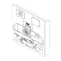
Carrier TRANSICOLD 69NT40-541-299 Operation And Service (154 pages)
Container Refrigeration Units
Brand:
Carrier TRANSICOLD
| Category:
Refrigerator
| Size: 6.53 MB
Table of Contents
Table of Contents
6
Fresh Air Makeup Vent
25
Figure 3.1 Refrigeration Unit - Front Section
25
Evaporator Section
26
Figure 3.2 Evaporator Section
26
Figure 3.3 Compressor Section
27
Air-Cooled Condenser Section
28
Figure 3.4 Air-Cooled Condenser Section
28
Water-Cooled Condenser Section
29
Figure 3.5 Water-Cooled Condenser Section
29
Control Box Section
30
Communications Interface Module
30
Figure 3.6 Control Box Section
30
Refrigeration System Data
31
Electrical Data
32
Safety and Protective Devices
33
Table 3-1 Safety and Protective Devices
33
Refrigeration Circuit
34
Figure 3.7 Refrigeration Circuit Schematic with Receiver
35
Figure 3.8 Refrigeration Circuit Schematic with Water Cooled Condenser
36
Microprocessor
37
Temperature Control Microprocessor System
37
Figure 4.1 Temperature Control System
37
Key Pad
38
Figure 4.2 Key Pad
38
Display Module
39
Figure 4.3 Display Module
39
Figure 4.4 Figure 3- 4 Micro-Link 3 Controller
39
Controller
40
Controller Software
40
Configuration Software (Configuration Variables)
40
Operational Software (Function Codes)
40
Modes of Operation
41
Temperature Control - Perishable Mode
41
Evaporator Fan Operation
41
Defrost Interval
41
Failure Action
41
Generator Protection
41
Condenser Pressure Control
42
Arctic Mode
42
Perishable Mode - Conventional
42
Perishable Mode - Economy
42
Perishable Mode - Dehumidification
43
Perishable, Dehumidification - Bulb Mode
43
Temperature Control - Frozen Mode
44
Frozen Mode - Conventional
44
Frozen Mode - Economy
44
Controller Alarms
44
Unit Pre-Trip Diagnostics
45
Datacorder
46
Description
46
Datacorder Software
47
Sensor Configuration (Dcf02)
47
Table 4-2 Datacorder Configuration Variables
47
Table 4-3 Datacorder Standard Configurations
48
Figure 4.5 Figure 3- 5 Standard Configuration Report
49
Logging Interval (Dcf03)
50
Thermistor Format (Dcf04)
50
Sampling Type (Dcf05 & Dcf06)
50
Alarm Configuration (Dcf07 - Dcf10)
50
Datacorder Power-Up
50
Pre-Trip Data Recording
50
Datacorder Communications
51
Figure 4.6 Data Reader
51
Figure 4.7 Databank Card
51
USDA Cold Treatment
52
USDA Cold Treatment Procedure
53
Datacorder Alarms
54
Table 4-4 Controller Configuration Variables
54
Table 4-5 Controller Function Codes
56
Table 4-6 Controller Alarm Indications
60
Table 4-7 Controller Pre-Trip Test Codes
64
Table 4-8 Datacorder Function Code Assignments
69
Table 4-9 Datacorder Pre-Trip Result Records
70
Table 4-10 Datacorder Alarm Indications
71
Operation
73
Inspection (before Starting)
73
Connect Power
73
Connection to 380/460 Vac Power
73
Connection to 190/230 Vac Power
73
Adjust Fresh Air Makeup Vent
74
Upper Fresh Air Makeup Vent
74
Figure 5.1 Autotransformer
74
Lower Fresh Air Makeup Vent
75
Figure 5.2 Make up Air Flow Chart
75
Fresh Air Position Sensor
76
Connect Water-Cooled Condenser
76
Water-Cooled Condenser with Water Pressure Switch
76
Water-Cooled Condenser with Condenser Fan Switch
76
Connect Remote Monitoring Receptacle
77
Starting and Stopping Instructions
77
Starting the Unit
77
Stopping the Unit
77
Start-Up Inspection
77
Physical Inspection
77
Check Controller Function Codes
77
Start Temperature Recorder
77
Complete Inspection
78
Pre-Trip Diagnosis
78
Table 5-1 Pre-Trip Selection Menu
78
Observe Unit Operation
79
Crankcase Heater
79
Probe Check
79
5.10 Sequence of Operation
80
Figure 5.3 Controller Operation - Perishable Mode
80
Figure 5.4 Controller Operation - Frozen Mode
81
Sequence of Operation - Perishable Mode Cooling
82
Figure 5.5 Perishable Mode Cooling
82
Sequence of Operation - Perishable Mode Heating
83
Figure 5.6 Perishable Mode Heating
83
Sequence of Operation - Frozen Mode Cooling
84
Figure 5.7 Frozen Mode
84
Sequence of Operation - Defrost
85
Figure 5.8 Defrost
85
Troubleshooting
87
Unit will Not Start or Starts then Stops
87
Unit Operates Long or Continuously in Cooling
87
Unit Runs but Has Insufficient Cooling
88
Unit will Not Heat or Has Insufficient Heating
88
Unit will Not Terminate Heating
88
Unit will Not Defrost Properly
88
Abnormal Pressures (Cooling)
89
Abnormal Noise or Vibrations
89
Controller Malfunction
89
6.10 no Evaporator Air Flow or Restricted Air Flow
90
6.11 Thermostatic Expansion Valve Malfunction
90
6.12 Autotransformer Malfunction
90
Service
91
Repairing the Refrigeration System
91
Piercing Valves
91
Removal
92
Manifold Gauge Set
92
Figure 7.1 Piercing Valve
92
Figure 7.2 Manifold Gauge Set
92
Refrigerant Recovery
93
Figure 7.3 Manifold Gauge Set Connection
93
Refrigerant Leak Checking
94
Evacuation and Dehydration
95
General
95
Preparation
95
Procedure - Complete System
95
Refrigerant Charge
96
Checking the Refrigerant Charge
96
Adding Refrigerant to System (Full Charge)
96
Adding Refrigerant to System (Partial Charge)
96
Emergency Shipboard Refrigerant Charging Procedure
96
Figure 7.4 Vacuum Pump Connections
97
Compressor
98
Removal and Replacement of Compressor
98
Figure 7.5 Compressor
98
Compressor Disassembly
99
Figure 7.6 Exploded View of Valve Plate
100
Figure 7.7 Bottom Plate Removed
100
Figure 7.8 Oil Pump and Bearing Head
101
Figure 7.9 Low Profile Oil Pump
102
Figure 7.10 Motor End Cover
102
Figure 7.11 Equalizing Tube and Lock Screw Assembly
103
Figure 7.12 Crankshaft Assembly
103
Compressor Reassembly
104
Preparation
104
Figure 7.13 Suction Valve & Positioning Springs
104
Figure 7.14 Piston Ring
104
Installing the Components
105
Compressor Oil Level
105
High Pressure Switch
106
Replacing High Pressure Switch
106
Checking High Pressure Switch
107
7.10 Condenser Coil
107
Figure 7.15 High Pressure Switch Testing
107
7.11 Condenser Fan and Motor Assembly
108
7.12 Water Cooled Condenser Cleaning
108
Figure 7.16 Water-Cooled Condenser Cleaning - Forced Circulation
110
Figure 7.17 Water Cooled Condenser Cleaning - Gravity Circulation
110
7.13 Filter-Drier
111
7.14 Thermostatic Expansion Valve
111
Figure 7.18 Thermostatic Expansion Valve Bulb
111
Checking Superheat
112
Hermetic Valve Replacement
112
Figure 7.19 Hermetic Thermostatic Expansion Valve Brazing Procedure
112
Semi-Hermetic Valve Replacement
113
7.15 Evaporator Coil and Heater Assembly
113
Evaporator Coil Replacement
114
Evaporator Heater Replacement
114
7.16 Evaporator Fan and Motor Assembly
114
Replacing the Evaporator Fan Assembly
114
Disassemble the Evaporator Fan Assembly
114
Assemble the Evaporator Fan Assembly
115
7.17 Evaporator Fan Motor Capacitors
115
When to Check for a Defective Capacitor
115
Figure 7.20 Evaporator Fan Assembly
115
Removing the Capacitor
116
Checking the Capacitor
116
7.18 Suction Modulation Valve
116
Figure 7.21 Suction Modulation Valve (SMV)
116
Precheck Procedure
117
Checking the Stepper Valve
118
Checking the Controller
118
7.19 Autotransformer
119
Power Factor Corrector Capacitors (Pfc)
119
Figure 7.22 Controller Section of the Control Box
120
Table 7-1 Sensor Temperature/Resistance Chart
123
Figure 7.23 Sensor Types
124
Figure 7.24 Sensor and Cable Splice
125
Figure 7.25 Supply Sensor Positioning
125
Figure 7.26 Return Sensor Positioning
125
Figure 7.27 Electronic Partlow Temperature Recorder
126
Figure 7.28 Door Hinge Repair
130
Table 7-2 Crack, Chip & Hole Repair Kit
130
Table 7-3 Insert Repair Kit
131
Table 7-4 Drill Information
131
Figure 7.29 Insert Location
132
Figure 7.30 Communications Interface Installation
133
Table 7-5 Recommended Bolt Torque Values (Dry, Non-Lubricated for 18-8 Stainless Steel)
134
Table 7-6 Wear Limits for Compressors
134
Table 7-7 Required Tools
135
Table 7-8 Compressor Torque Values
136
Table 7-9 R-134A Temperature - Pressure Chart
137
Figure 7.31 R-134A Compressor Pressure and Motor Current Curves Vs Ambient Temp (1 of 2)
138
Figure 7.32 R-134A Compressor Pressure and Motor Current Curves Vs Ambient Temp (2 of 2)
139
Figure 8.1 Legend
142
Figure 8.2 Schematic Diagram
143
Figure 8.3 Schematic Diagram - Transfresh and Vent Position Sensors (VPS)
144
Figure 8.4 Schematic Diagram, Wiring Diagram - Electronic Partlow Recorder
145
Related Products
Carrier TRANSICOLD PrimeLINE 69NT40-571-001
Carrier TRANSICOLD PrimeLINE 69NT40-571-199
Carrier TRANSICOLD PrimeLINE ONE 69NT40-575-001
Carrier TRANSICOLD PrimeLINE ONE 69NT40-575-199
Carrier TRANSICOLD 69NT40-511-200
Carrier TRANSICOLD 69NT40-511-299
Carrier TRANSICOLD 69NT40-489
Carrier TRANSICOLD 69NT40-541-200
Carrier TRANSICOLD 69NT40-531 Series
Carrier TRANSICOLD PrimeLINE 69NT40-571-100
Carrier TRANSICOLD Categories
Refrigerator
Automobile Accessories
Cooling boxes
Air Conditioner
Accessories
More Carrier TRANSICOLD Manuals