Yamaha QL5 Owner's Manual
Yamaha digital mixing console owner's manual
Hide thumbs
Also See for QL5:
- Service manual (367 pages) ,
- Reference manual (294 pages) ,
- Manual (100 pages)
Table of Contents
Quick Links
Table of Contents

Related Manuals for Yamaha QL5


Summary of Contents for Yamaha QL5
- Page 1 Owner’s Manual Keep This Manual For Future Reference.
-
Page 2: Table Of Contents
Contents Quick Guide ........34 Connecting the devices........34 Setting the input channels .......35 PRECAUTIONS........5 Sending an input channel signal to the STEREO bus..........36 Applying EQ/dynamics........36 Introduction ........8 Setting the output channels ......37 Accessories............8 Using GEQ ............37 About utility software.........8 Using Automixer ..........38 About firmware updates........8 Applying effects ..........38... -
Page 3: Important Safety Instructions
The above warning is located on the rear/side of the unit. L’avertissement ci-dessus est situé sur le arrière/côté de l’appareil. Explanation of Graphical Symbols Explication des symboles The lightning flash with arrowhead symbol within an equilateral triangle is intended to alert the user to the presence of uninsulated “dan- gerous voltage”... - Page 4 The above statements apply ONLY to those products distributed by of other electronic devices. Compliance with FCC regulations does Yamaha Corporation of America or its subsidiaries. * This applies only to products distributed by YAMAHA CORPORATION OF AMERICA. (class B) ADVARSEL!
-
Page 5: Precautions
If some trouble or malfunction AC outlet. Then have the device inspected by qualified Yamaha occurs, immediately turn off the power switch and disconnect service personnel. -
Page 6: Backup Battery
If the backup battery power is fully depleted, have qualified Yamaha service personnel replace the battery. Yamaha cannot be held responsible for damage caused by improper use or modifications to the device, or data that is lost or destroyed. -
Page 7: About This Manual
“Low Battery” when you start up the system. In this case, contact your Yamaha dealer and have qualified [Information on Disposal in other Countries outside the Yamaha service personnel replace the backup battery. -
Page 8: Introduction
Introduction About the Owner’s Manual Owner’s Manual (this document) Thank you for choosing a Yamaha QL series QL5/QL1 Digital Mixing Console. To take full advantage of the This book primarily explains panel controls and superior features and performance offered by your QL functions and basic operation of the QL series. -
Page 9: An Overview Of The Ql Series
An overview of the QL series An overview of the The Dante Virtual Soundcard software enables you to carry out multi-channel recording to DAW software installed on a computer. Consequently, no other audio QL series interface is needed. Integration of mixer and I/O device with port-to-port functionality Features Direct “port-to-port”... -
Page 10: About The Models
About the models I/O card and processing card expansion The QL series is available in two models: QL5 and QL1. The rear panel provides two slots in which separately Model differences are shown in the table below. sold mini-YGDAI cards can be installed. You can add... -
Page 11: Controls And Functions
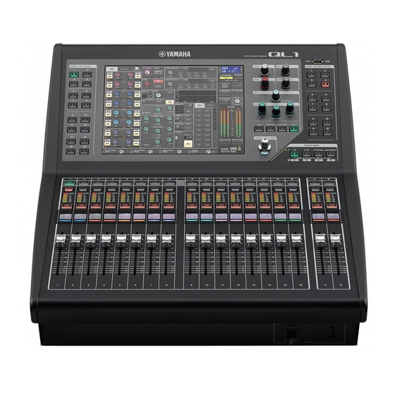
Selected Channel section page 13 USB connector page 15 USER DEFINED KEYS section page 14 FADER BANK section page 14 Master section page 14 NOTE This illustration shows the top panel of the QL5. Owner’s Manual... -
Page 12: Channel Strip Section
Controls and functions Channel Strip section Channel name display Indicates the channel name, fader value, etc. You can set the display so that it will indicate only the channel name. The information to be shown can be specified in the USER SETUP screen PREFERENCE tab. -
Page 13: Display Section
Top panel Display section NOTE • The PAD will be switched on or off internally when the HA This is a touch screen that you can operate by touching analog gain is adjusted between +17dB and +18dB. Keep the surface of the screen. You can touch your finger to in mind that noise may be generated when using phantom the screen to select menus or set parameters. -
Page 14: Master Section
Controls and functions USER DEFINED KEYS section Master section This section is similar to the Channel Strip section, and USER DEFINED keys [1]–[12] enables you to control the principal parameters of the Execute functions as assigned by the assigned channels. When the unit is in the default state, user (scene changes, switching the STEREO/MONO channels are assigned. -
Page 15: Front Panel
Front panel Front panel Fader Adjusts the output level of the channel. If MONITOR has been assigned, this fader adjusts the monitor output level. USB connector You can connect a USB flash drive to the USB connector to record or play audio files, and to save or PHONES LEVEL knob load internal data. -
Page 16: Rear Panel
XLR-3-32 male output jacks for outputting analog the unit for a long period of time, remove the power cable audio signals. (The QL5 has 16 of these jacks. The from the AC outlet. QL1 has 8.) These jacks are used mainly to output AC IN connector the signals of MIX channels or MATRIX channels. - Page 17 Rear panel MIDI IN/OUT connectors Used to transmit and receive MIDI messages to and from external MIDI devices. The MIDI IN connector receives messages from an external device, and the MIDI OUT connector transmits messages from the QL unit. These are used mainly to record QL parameter operations or scene/library selections on an external device, or to control QL parameters from an external device.
-
Page 18: Touch Screen
Touch screen Touch screen Using the [TOUCH AND TURN] knob The [TOUCH AND TURN] knob is used to operate the knobs selected for operation in the touch screen. Press the touch screen to select the knob you want to operate. When you press a knob, a highlight outline is Basic touch screen displayed around that knob. -
Page 19: Keyboard Window
On-screen user interface Keyboard window Dialog boxes Displayed when you need to assign a name or comment Dialog boxes similar to the following enable you to to a scene or library, or when you need to assign a confirm operations you just performed. Press the OK channel name. -
Page 20: Viewing The Touch Screen
Touch screen Viewing the touch screen unit while this indicator is shown. Doing so may damage your flash drive, or may damage the data in the QL unit or on your media device. The touch screen of the QL series is broadly divided into HELP two areas. -
Page 21: Using The Tool Buttons
Using the tool buttons When you press a button (7–0, B–D) to access the Using the tool buttons corresponding screen, the button will be highlighted. In this state, pressing the button once again will return The title bar at the top of some windows contains tool either to the most recently recalled SELECTED buttons that provide additional functions. -
Page 22: Basic Operation Of The Ql Series
Select the custom fader bank you want to set. Press the [SEL] key to select the target channel. The channel strip is divided into 1 16, 17 24 (QL5 – – Press one of the knobs in the Selected Channel only), and Master, from the left side of the console. -
Page 23: Assigning A Name
Assigning a name To assign channels to other faders, repeat step Repeat steps 1–3 to adjust the send level for other MIX/MATRIX buses in the same way. When you have finished, press the X symbol in When you’ve finished setting the MIX/MATRIX the upper right corner of the screen, and press send levels, press the key that is flashing in the the SETUP button again to return to the SELECT... -
Page 24: Using Libraries
Basic operation of the QL series Using libraries Press the keyboard window in the touch screen to enter the desired characters. You can use libraries to store (save) or recall (load) the While entering characters, you can use the settings of the currently selected channel following buttons in the keyboard window. - Page 25 Using libraries [HPF/EQ screen]/[DYNAMICS 1/2 screen] Select the channel (EQ/dynamics) or rack In the SELECTED CHANNEL VIEW screen or the (GEQ/effect/Premium Rack) for which you want OVERVIEW screen, press any knob in the to recall settings. appropriate field for EQ or Dynamics 1/2. (In the The method of selecting a channel/rack will depend SELECTED CHANNEL VIEW screen, press any knob on the type of window that is currently displayed.
- Page 26 Basic operation of the QL series [VIRTUAL RACK screen] Rotate the [TOUCH AND TURN] knob to move Use the rack select tabs at the bottom of the the highlight line up or down to select a library window to select a rack. item you want to recall.
- Page 27 Using libraries Storing settings in a library • Be aware that if you store settings to a location that already contains data, the existing data will be overwritten. (Read-only data cannot be overwritten.) Access a window that contains tool buttons. Select the channel (EQ/dynamics) or rack ...
-
Page 28: Initializing Settings
Basic operation of the QL series Initializing settings Press the COPY button. The current settings will be copied to buffer Here’s how you can return the EQ/dynamics settings of memory. the currently selected channel or the effect settings of a NOTE rack to their initial state. -
Page 29: Comparing Two Sets Of Settings
Comparing two sets of settings Comparing two sets of To compare the first set of settings with the current settings (the second set), press the settings COMPARE button. You will return to the first version of your settings. You can use the COMPARE button to switch between At this time, the second version of your settings will the settings copied to the buffer memory and the settings be copied to buffer memory. -
Page 30: Connection
• It transmits up to 512 in/512 out, for a total 1024 power to the QL series console. channels (in theory) of audio over a GbE network. (The QL series features QL5: 64 in/64 out, QL1: 32 Daisy chain network in/32 out with a 24/32-bit resolution.) •... - Page 31 Connecting to I/O devices Connecting QL series consoles and I/O using a redundant network with a star topology is better for increasing communication stability compared to a devices daisy chain network. Use the Dante connectors on the QL series console and I/O devices to connect them as follows.
-
Page 32: Audio Input/Output Connections
Connection Audio input/output Analog output connections To the OMNI OUT jacks on the QL series and the connections OUTPUT jacks on I/O devices, you can patch the output signals from output channels [MIX, MATRIX, STEREO (L/R), MONO (C)], monitor signals (MONITOR OUT Analog input connections L/R/C channels), and the direct out signals of the input INPUT jacks on the console and I/O devices are used... -
Page 33: Installing An Optional Card
Installing an optional card Before you install I/O cards in slots 1–2, you must check the Yamaha website to determine whether the card is NOTE compatible with the QL series, and to verify the total When installing a card, carefully align both edges of the number of Yamaha or third-party cards that can be card with the guide rails in the slot of the device. -
Page 34: Quick Guide
This section explains the general procedures in a mixing work flow. The example below is based on a system in which one QL5, one I/O device, an amplifier and speakers are connected. If there are multiple methods to Connecting an I/O device achieve the same result, this section describes the simplest method. -
Page 35: Setting The Input Channels
Setting the input channels Setting the input channels Patching the input port Press the I/O DEVICE button in the touch screen. Phantom power on/off Press the DANTE PATCH tab in the upper part of the I/O Press the [SEL] key for the channel that you want DEVICE screen. -
Page 36: Sending An Input Channel Signal To The Stereo Bus
Quick Guide Applying EQ/dynamics Adjust the gain level for other channels in the same way, by pressing their [SEL] and [CUE] keys, and then rotating the [GAIN] knobs. Applying EQ After adjustment is complete, switch the [CUE] key off (the key LED turns off). Press the [SEL] key of the channel that you want to control. -
Page 37: Setting The Output Channels
Setting the output channels Using GEQ Applying dynamics Press the [SEL] key of the channel that you want Press the RACK button in the touch screen. to control. Press any one of the knobs in the Selected Channel section, to return to the SELECTED CHANNEL VIEW screen. -
Page 38: Using Automixer
Quick Guide Using Automixer Press the rack container in which you mounted Automixer. Press the RACK button in the touch screen. Making sure no one is speaking into any microphones, adjust the head amp gain (or Press the GEQ tab. fader) until the level indicator remains green. - Page 39 Applying effects Select an effect you want to use from the EFFECT Inserting PREMIUM RACK processors TYPE window. Press the RACK button in the touch screen. Press the PREMIUM tab. Press the rack icon in the middle to open the PREMIUM RACK MOUNTER window.
-
Page 40: Changing The Patch Settings
Quick Guide In the Channel Strip section, select the bank that Assign OUT and IN for INSERT or DIRECT OUT. includes the channel for the premium rack you want to use. Press the [SEL] key of the channel for the premium rack you want to use. -
Page 41: Grouping And Linking
Grouping and linking Using talkback Press the output channel select button to select the output channel for which you want to change the port. Plug the microphone to use for talkback into the INPUT jack on the rear panel. Press the MONITOR button in the touch screen. Grouping and linking Press the TALKBACK ASSIGN field in the TALKBACK area. -
Page 42: Routing The Oscillator To An Output Channel
Quick Guide Routing the oscillator to an Using scene memories output channel Storing a scene Press the MONITOR button in the touch screen. Press the SCENE field in the function access area. Press the OSCILLATOR display button. Turn the [TOUCH AND TURN] knob to select the store-destination scene number. -
Page 43: Recording And Playing Audio Using A Usb Flash Drive
Recording and playing audio using a USB flash drive Recording and playing audio Playing audio files from a USB flash drive using a USB flash drive Connect a USB flash drive that contains audio files to the QL unit. Recording to USB flash drive Press the RECORDER button in the touch screen. -
Page 44: Saving And Loading The Unit Settings
Quick Guide Saving and loading the unit Enter the data name and comments, then press the SAVE button. settings Loading the unit settings from a USB Saving the unit settings to a USB flash flash drive drive Press the SETUP button in the touch screen. Connect a USB flash drive to the USB connector Press the SAVE/LOAD button. -
Page 45: Other Functions
Other functions Other functions If desired, switch between banks A/B and make settings for the other bank in the same way. Now you can switch between the BANK A and BANK B buttons to change the brightness of the touch screen, LCD, channel name displays, and lamps in a single operation. -
Page 46: Initializing The Unit To Factory Default Settings
Other functions Initializing the unit to Adjusting the faders factory default settings (Calibration function) If an error occurs in the QL’s internal memory, or if you Depending on the environment in which you use the forget the password and cannot operate the unit, you console, discrepancies may occur in the motion of the can use the following procedure to initialize the internal motor faders. - Page 47 Adjusting the faders (Calibration function) Repeat steps 6 to 7 to adjust the fader position to 20dB, 0dB, and +10dB (all the way up), in order. When adjustment to the +10dB position is complete, calibration starts. When calibration has been completed, press the APPLY button.
-
Page 48: Troubleshooting
Gain Compensation is clicked and locked in securely? turned on? If the power still does not turn on, contact your Yamaha First turn the Gain Compensation function off, set the dealer. analog gain to an appropriate level, and then turn Gain Compensation back on. - Page 49 Troubleshooting There is insufficient headroom, especially when EQ When you recall a scene, it takes a certain amount of boost is applied. time for the faders to stop. Use the EQ attenuator function to lower the level. Could you have specified a fade time? An input signal is being input, but there is no The panel LEDs or LCD display are too dark/too monitor output.
-
Page 50: Attaching The Rk1 Rackmount Kit (Sold Separately)
Attaching the RK1 rackmount kit (sold separately) You can attach the optional RK-1 rackmount kit to the QL5 and QL1 and mount it in a rack or an installed system. Make sure that the power is turned off. Remove screws “... -
Page 51: General Specifications
Specifications and descriptions in this owner’s manual are for information purposes only. Yamaha Corp. reserves the right to change or modify products or specifications at any time without prior notice. Since specifications, equipment or options may not be the same in every locale, please check with your Yamaha dealer. Owner’s Manual... -
Page 52: Dimensional Diagrams
Dimensional Diagrams Dimensional Diagrams 828.4 Units: mm Owner’s Manual... -
Page 53: Index
Index Index Main area ........21 MIX/MATRIX buses. -
Page 55: Block Diagram
Self POST EQ To MIX RECORDER CUE POST ON MIX13-16 OUT MIX2,4...16 ST R POST ON FIXED CH[1-8,9-16,17-24,25-32,33-40,41-48, 49-56, 57-64,ST IN 1L-8R]POST EQ(QL5) CH[1-8,9-16,17-24,25-32,ST IN 1L-8R]POST EQ(QL1) FX1-8 OUT To MIX POST PAN L A(L)/B(R) FIXED STEREO POST PAN R... -
Page 56: Level Diagram
Level Diagram Analog Digital Digital Analog Φ MASTER Analog Digital Analog LEVEL LEVEL MASTER φ OUTPUT GAIN INSERT ATT. (x4) INSERT DELAY /ON PAN Adder INSERT ATT. (x4) / BAL PATCH DELAY dBFS Digital Clipping Level Max. Input [+30dBu] Max. Output [+24dBu] CASCADE IN CASCADE OUT... - Page 57 Niederlassung und bei Yamaha Vertragshändlern in den jeweiligen Bestimmungsländern erhältlich. Pour plus de détails sur les produits, veuillez-vous adresser à Yamaha ou au distributeur le plus proche de vous figurant dans la liste suivante. Para detalles sobre productos, contacte su tienda Yamaha más cercana o el distribuidor autorizado que se lista debajo.
- Page 58 Yamaha Pro Audio Global Web Site http://www.yamahaproaudio.com/ Yamaha Manual Library http://www.yamaha.co.jp/manual/ C.S.G., PA Development Division © 2014 Yamaha Corporation 405MATO-B0 Printed in Japan ZH99130...