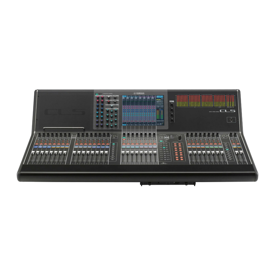
Yamaha CL5 Reference Manual
Dgital mixing console yamaha cl5; cl3; cl1
Hide thumbs
Also See for CL5:
- Reference manual (306 pages) ,
- Owner's manual (67 pages) ,
- Supplementary manual (26 pages)
Table of Contents
Quick Links
How to Use This Reference Manual
The CL5/CL3/CL1 Reference Manual (this document) allows you to
search for terms and take advantage of links in the text.
Searching for terms
To search for a term, use the search function of the software you're using
to view this document.
If you're using Adobe Reader, enter the term in the search box and press
the key of your computer keyboard to search for occurrences of
that term.
Displaying the next/previous view
If you're using Adobe Reader, you can jump to the previous/next view in
your viewing history. This is a convenient way to jump back to the
previous page after you've used a link to jump to a different page.
Reference Manual
Using the Function Tree
A function tree for the CL5/CL3/CL1 is provided on
page 4
and
following. You can use this function tree to find the page that explains
an on-screen display or function.
EN
Table of Contents

Related Manuals for Yamaha CL5


Summary of Contents for Yamaha CL5
-
Page 1: How To Use This Reference Manual
How to Use This Reference Manual The CL5/CL3/CL1 Reference Manual (this document) allows you to search for terms and take advantage of links in the text. Searching for terms To search for a term, use the search function of the software you’re using to view this document. -
Page 2: Table Of Contents
Contents Contents EQ and Dynamics ..............About EQ and dynamics ................. Using EQ ......................Using dynamics ....................How to Use This Reference Manual ..............Using the EQ or Dynamics libraries ..............Function Tree ................Grouping and linking .............. SELECTED CHANNEL section ............About DCA groups and Mute groups.............. - Page 3 Contents Graphic EQ, effects, and Premium Rack ....... Other functions ..............About the virtual rack ................... About the SETUP screen................Virtual rack operations .................. Word clock and slot settings ................. Graphic EQ operations.................. Using cascade connections ................About the internal effects................Basic settings for MIX buses and MATRIX buses ..........
-
Page 4: Function Tree
Function Tree Function Tree SEND TO/SEND FROM MONITOR TO STEREO/MONO MONITOR Page numbers in parentheses ( ) are the page numbers of the Owner’s Manual (booklet). CH1-48 MONITOR CH49-72/ST IN OSCILLATOR Main OUTPUT TALKBACK SELECTED CHANNEL OVERVIEW LIBRARY FUNCTION ACCESS AREA (20) METER CHANNEL LIBRARY... - Page 5 CHANNEL COLOR CALIBRATION RECORDER NOTE NUENDO LIVE • The explanations in this reference manual will use the CL5. • In the case of the CL3/CL1, some screens will not show channels and faders that do not exist on those models. CH JOB...
-
Page 6: Selected Channel Section
SELECTED CHANNEL section SELECTED CHANNEL section Press one of the knobs in the SELECTED CHANNEL section. Press a knob in the SELECTED CHANNEL section to display the SELECTED CHANNEL VIEW screen for the currently-selected channel. If you leave this screen displayed, you will always be able This chapter explains how to use the SELECTED CHANNEL section and the SELECTED CHANNEL to view the settings in the screen while operating the knobs in the SELECTED CHANNEL VIEW screen to control the selected channel. -
Page 7: Selected Channel View Screen
SELECTED CHANNEL section SELECTED CHANNEL VIEW screen If the destination bus channels are two mono channels: SEND knob Sets the send level to the corresponding bus. PRE indicator Indicates the type of the corresponding bus. If the type is VARI [PRE EQ] or VARI [PRE FADER], and if the PRE button on the MIX SEND 8ch screen is turned ON, this PRE indicator will be turned on. - Page 8 SELECTED CHANNEL section ■ GAIN/PATCH field ST/MONO button Switches the on/off status of a signal sent from the This field enables you to make HA (head amp) analog gain settings, and view the operational status of channel to the STEREO/MONO bus. the head amp.
- Page 9 SELECTED CHANNEL section ■ EQ parameter field ■ EQ graph field This field displays the 4-band EQ parameter settings. This field graphically indicates the approximate response of the EQ. Press this field to open the HPF/ EQ 1ch popup window, in which you can set the attenuator, HPF and EQ. Q knob Indicates the Q for each band.
- Page 10 SELECTED CHANNEL section ■ INSERT field ■ FADER field This field enables you to make insert settings. This field enables you to view and make settings for the channel on/ off status and the level. Popup button Fader Press this button to open the INSERT/DIRECT OUT 1ch popup window.
-
Page 11: Centralogic Section
Centralogic section Centralogic section Operations in the Centralogic section Follow the steps below to perform operations in the Centralogic section. This chapter explains how to use the Centralogic section and the OVERVIEW screen to simultaneously control up to eight channels. Use the Bank Select keys in the Centralogic section to select the channels or DCA groups that you want to control. -
Page 12: Overview Screen
Centralogic section ■ GAIN/PATCH field OVERVIEW screen This field enables you to make HA (head amp) analog or digital gain settings and view the operational status of the head amp. The view and the function of the controllers in this field vary depending on the type of the selected channel. - Page 13 Centralogic section ■ INPUT DELAY field ■ SEND field This field displays the delay status for the input channel. If an output channel has been selected, this This field displays the send level, send on/off status, and pre/post settings for 16 field will be blank.
- Page 14 Centralogic section ■ TO STEREO/MONO field ■ DCA group field This field displays the on/off status and pan/balance setting of the signal sent to the STEREO/MONO A DCA group (1–16) to which the channel is assigned is displayed on the first or second row in this bus.
-
Page 15: Input And Output Patching
Input and output patching Input and output patching Input patching CL series consoles and I/O racks feature two types of patching: Dante audio network patching and CL console internal patching. This chapter explains how to edit the input patching and output patching, how to connect inserts, and For Dante audio network patching, you will use the DANTE INPUT PATCH popup window. -
Page 16: Changing The Output Patch Settings
Input and output patching Changing the output patch settings In the PATCH/NAME popup window you can change the channel name, icon, and output port assigned to each output channel. The window includes the following items. To change the patching, you can either select the output port that will be the output destination of each output channel, or you can select the output channel that will be the output source for each output port. - Page 17 Input and output patching Selecting the output channel for each output port Channel name edit box Indicates the currently-specified channel. Press the inside of this box to enable the NAME tab at the bottom of the screen. The SOFT KEYBOARD popup window will appear, enabling you to edit In the Function Access Area, press the SETUP button to access the SETUP screen.
-
Page 18: Outport Setup
Input and output patching In the OUTPORT SETUP popup window, you can assign the source channel for each output port. DELAY button This popup window includes the following items. Switches the output port delay on or off. Ø (Phase) button Switches the phase of the signal assigned to the output port between normal phase (black) and reverse phase (yellow). -
Page 19: Changing The Input Patch Settings
Input and output patching The CH SELECT popup window will appear. This popup window includes the following items. Use the channel select tabs and the channel select buttons to select the source channel, and press the CLOSE button. You will return to the OUTPORT SETUP popup window. NOTE If PATCH CONFIRMATION is ON, a confirmation dialog box will appear when you attempt to change the patch settings. - Page 20 Input and output patching In the PATCH/NAME popup window you can view and change the channel name, icon, channel • EFFECT RACK..FX1L(A)–FX8R(B) color, and input port assigned to each input channel. • PREMIUM RACK..PR1L(A)–PR2R(B) Input port select buttons Assign an input port to the currently-selected input channel.
-
Page 21: Inserting An External Device Into A Channel
Input and output patching Inserting an external device into a channel INSERT ON/OFF button Switches the insert on or off. If desired, you can insert an effect processor or other external device into the signal path of an INPUT, To change the currently-selected insert point, press one of the three blocks that does not contain MIX, MATRIX, STEREO, or MONO channel. - Page 22 Input and output patching INSERT/DIRECT OUT popup window (8ch) Access either the one-channel or the eight-channel INSERT/DIRECT OUT popup window, and then press the INSERT OUT popup button. The PORT SELECT popup window will appear, allowing you to select the output port used for insert-out.
-
Page 23: Directly Outputting An Input Channel
Input and output patching Directly outputting an INPUT channel Use the output port select tabs and the output port select buttons to specify the output port that will be used as insert-out, and press the CLOSE button. The signal of an INPUT channel can be output directly from an OUTPUT jack on the I/O rack, from You will return to the INSERT/DIRECT OUT popup window. - Page 24 Input and output patching DIRECT OUT PATCH button Access either the one-channel or the eight-channel INSERT/DIRECT OUT popup window, and press the DIRECT OUT popup button. Press this button to open the PORT SELECT popup window, in which you can select a Direct Out output port.
-
Page 25: Recording Or Playing Back Using Daw On A Computer
Input and output patching Recording or playing back using DAW on a Press the DIRECT OUT ON/OFF button to turn it ON. In this state, direct output is enabled. Adjust the input level of your external device as necessary. computer NOTE If you plan to add DAW software, such as Steinberg Nuendo, to an audio network that includes a CL With the factory settings, all are turned off. -
Page 26: Word Clock Settings
Input and output patching Word clock settings Setting up Dante Controller In a Dante network, the master device supplies accurate word clock to other devices on the network. If Connect the network port on the computer to a GbE-compatible network switch. Configure the the master device is removed from the network or breaks down, another device will automatically take computer to obtain an IP address automatically (this is the default setting). -
Page 27: Input Channels
This is a high pass filter that cuts the region below the specified frequency. Self POST EQ To MIX POST ON MIX21-24 OUT MIX2,4...24 FIXED CH[1-8,9-16,17-24,25-32,33-40,41-48, 49-56, 57-64, 65-72]POST EQ(CL5) CH[1-8,9-16,17-24,25-32,33-40,41-48, 49-56, 57-64]POST EQ(CL3) To MIX CH[1-8,9-16,17-24,25-32,33-40,41-48]POST EQ(CL1) POST PAN L FIXED • 4 BAND EQ (4 band equalizer) -
Page 28: Specifying The Channel Name And Icon
Input channels Specifying the channel name and icon • LCR (Left/Center/Right) Sends the input channel signal to the STEREO bus/MONO bus as a three-channel signal that On the CL series unit, you can specify the on-screen name and icon for each input channel. This section consists of the L/R channel plus the center channel. - Page 29 Input channels This popup window contains the following items: Press the desired channel icon button. The lower part of the popup window will change as follows. Channel color select buttons PATCH button Select a channel color. Pressing the button will immediately apply the change. Indicates the currently-patched port.
-
Page 30: Making Ha (Head Amp) Settings
Input channels Making HA (Head Amp) settings If you want to enter a channel name directly (or edit a sample name that has been entered), press the channel name field in the upper part of the window. This section explains how to make HA (Head Amp) related settings (phantom power on/off, gain, The keyboard window will appear in the lower part of the screen, allowing you to enter or edit the phase) for each input channel. - Page 31 Input channels GAIN/PATCH popup window (1 ch) • Gain compensation meter Indicates the level of the signal output to the audio network after gain compensation. INPUT PORT button Indicates the port that is assigned to the channel. Press the button to display the PATCH popup window, in which you can select a port to patch.
- Page 32 Indicates the level after digital gain. GAIN/PATCH popup window (1-48, 49-72/ST IN(CL5), 49-64/ST IN(CL3), ST IN(CL1)) This window displays the head amp settings of the corresponding input channels. Here you can also adjust the head amp gain in groups of the selected eight channels by using the multifunction knobs in the Centralogic section.
- Page 33 INPUT jack on the I/O rack, the OMNI IN on the CL unit, or a slot that is connected NOTE to an external head amp device (e.g., Yamaha AD8HR or SB168-ES). If the input channel is patched to a slot for which the connection to the head amp is not recognized, the knob will be replaced with the slot/port number of the patch destination.
- Page 34 Input channels Setting the Gain Compensation function Adjusting the digital gain If you are using an I/O rack (such as an Rio3224-D) on a Dante network, you can maintain the constant If the Gain Compensation function is turned on, digital gain will be used to adjust the level of the signal level of signal output to the audio network by using the Gain Compensation function.
-
Page 35: Sending A Signal From An Input Channel To The Stereo/Mono Buses
Input channels Relationship between analog and digital gain while Gain Sending a signal from an input channel to the Compensation is on STEREO/MONO buses If Gain Compensation is on, adjusting the analog gain by a specific amount will cause the I/O rack to This section explains how to send a signal from an input channel to the STEREO bus or MONO bus. - Page 36 Input channels TO STEREO/MONO popup window (8ch) Make sure that an input source is connected to the input channel you are adjusting. Set the phantom power, gain, and phase of the head amp to obtain the optimum Here you can control the on/off and pan/balance settings of signals sent from input channels to the input signal.
-
Page 37: Ch49-72/St In
Input channels TO STEREO/MONO popup window (CH1-48, CH49-72/ST IN(CL5), CH49-64/ST IN(CL3), ST IN(CL1)) Adjusts the status of a signal sent from the corresponding input channel to the STEREO/MONO bus. You can also adjust the pan or balance setting in groups of eight selected channels. - Page 38 Input channels Use the MODE button to select either ST/MONO mode or LCR mode for each In the TO STEREO/MONO popup window, use the TO ST PAN knob to set the channel. panning of signals sent from the input channel to the STEREO bus and MONO (C) bus.
-
Page 39: Sending A Signal From An Input Channel To A Mix/Matrix Bus
Input channels Sending a signal from an input channel to a MIX/ If the CSR knob is set to 100%, operating the INPUT TO ST PAN knob will change the level of signals sent to the STEREO (L/R) bus and MONO (C) bus, as shown in the following diagram. MATRIX bus This section explains how to send a signal from an input channel to MIX buses 1–24 and MATRIX Signal sent to the MONO (C) bus... - Page 40 Input channels Press a knob in the SELECTED CHANNEL section to access the SELECTED CHANNEL VIEW screen. If necessary, you can specify two adjacent odd/even-numbered MIX/MATRIX buses as a stereo bus and link the main parameters. If the send-destination MIX/MATRIX bus is assigned as stereo, the left knob of the two adjacent TO MIX/MATRIX SEND LEVEL knobs will operate as the TO MIX/MATRIX PAN knob.
-
Page 41: Using The Centralogic Section
Input channels Using the Centralogic section Use multifunction knobs 1–8 to adjust the send level of signals sent from the (up to) eight input channels to the selected MIX/MATRIX bus. You can use the multifunction knobs in the Centralogic section to adjust the send level of signals sent If necessary, you can use the Bank Select keys to switch the input channels that you want to assign from eight consecutive input channels to a specific MIX/MATRIX bus. - Page 42 Input channels Channel select button The knob for the mode selected here will appear. Selects the send-source channel that you wish to control. The current channel icon, number, and color appear on the button, and the channel name appears immediately below the button. PRE/POST button Switches the send point of each send-source channel between PRE and POST.
- Page 43 Input channels Using the faders (SENDS ON FADER mode) Use the MIX/MATRIX bus selection buttons in the Function Access Area to select the send-destination MIX/MATRIX bus. You can use the faders on the top panel to adjust signals that are sent from all input channels to a specific MIX/MATRIX bus.
-
Page 44: Correcting Delay Between Channels (Input Delay)
Input channels Correcting delay between channels (Input Delay) INPUT DELAY (8ch) This section explains how to correct delay between input channels by using Input Delay function. This function is useful when you want to correct the phase variance, caused by microphone locations on the stage, to add depth to the sound by using phase variance, or to correct a delay (a gap) that may exist between video and audio that are sent from a site for broadcast on TV. -
Page 45: Channel Library Operations
Input channels INPUT DELAY (CH1-48, CH49-72/ST IN(CL5), Channel library operations CH49-64/ST IN(CL3), ST IN(CL1)) Channel libraries include “INPUT CHANNEL LIBRARY, ” which enables you to store and recall various parameters (including the head amp settings) for input channels. To recall a library, press the corresponding LIBRARY button in the SELECTED CHANNEL VIEW screen. -
Page 46: Output Channels
Output channels Output channels STEREO channel/MONO (C) channel Each of these channels processes the signal sent from the input channels to the STEREO bus or MONO (C) bus, and send it to the corresponding output port or MATRIX bus. If input channels are in LCR This chapter explains output channels (MIX channels, MATRIX channels, STEREO channels, MONO mode, the STEREO (L/R) channels and the MONO (C) channel can be used together as a set of three channels). -
Page 47: Specifying The Channel Name And Icon
Output channels Specifying the channel name and icon • MATRIX ON/OFF (MATRIX send on/off) This is an on/off switch for signals sent from the MIX channels, STEREO (L/R) channel, or This section explains how to specify the channel name and icon for each output channel. MONO (C) channel to each MATRIX bus. -
Page 48: Sending Signals From Mix Channels To The Stereo/Mono Bus
Output channels Sending signals from MIX channels to the STEREO/ MONO bus This section explains how to send a signal from a MIX channel to the STEREO bus or MONO bus. There are two ways to send signals to the STEREO bus or MONO bus: ST/MONO mode and LCR mode. -
Page 49: To Stereo/Mono
Output channels TO STEREO/MONO popup window (8ch) If the ST/MONO/LCR mode select button is set to LCR mode, the following button and knob are displayed instead of the ST/MONO button ( You can control the on/off and pan/balance settings of the signal sent from MIX channels to the STEREO (L/R) bus and MONO (C) bus, in groups of eight channels. -
Page 50: Ch1-48
TO STEREO/MONO popup window (CH1-48, Access the eight-channel TO STEREO/MONO popup window. CH49-72/ST IN(CL5), CH49-64/ST IN(CL3), ST IN(CL1), OUTPUT) Use the MODE button to select either ST/MONO mode or LCR mode for each This window displays the status of signals sent from the corresponding channel to the STEREO bus/ channel. -
Page 51: Sending Signals From Mix Channels And Stereo/Mono Channels To Matrix Buses
Output channels Sending signals from MIX channels and STEREO/ Press a knob in the SELECTED CHANNEL section to access the SELECTED CHANNEL VIEW screen. MONO channels to MATRIX buses This section explains how to send a signal from a MIX or STEREO/MONO channel to MATRIX buses 1–8. - Page 52 Output channels Using the Centralogic section Use multifunction knobs 1–8 to adjust the send level of the signals sent from up to eight MIX channels or the STEREO/MONO channels to the selected MATRIX bus. This method lets you use the multifunction knobs (in the Centralogic section) to simultaneously adjust If necessary, you can use the Bank Select keys and the [SEL] keys in the Centralogic section to the send levels from the eight channels selected in the Centralogic section to the desired MATRIX bus.
- Page 53 Output channels Send destination select buttons The knob for the mode selected here will appear. Select MIX/MATRIX buses as the send destination. Channel select button Selects the send-source channel that you wish to control. The current channel icon, number, and color appear on the button, and the channel name appears immediately below the button.
-
Page 54: Correcting Delay Between Channels (Output Delay)
Output channels Correcting delay between channels (Output Delay) This section explains how to correct delay between output channels by using the Output Delay function. This Output Delay function is useful when you want to correct the timing of output signals sent to speakers that are located at a distance from each other. -
Page 55: Eq And Dynamics
EQ and Dynamics EQ and Dynamics HPF/EQ popup window (1ch) This lets you view and edit all EQ parameters of the currently-selected channel. This is convenient if you want to make detailed EQ settings for a specific channel. This chapter explains the EQ (equalizer) and dynamics that are provided on each channel of the CL series console. - Page 56 EQ ON/OFF button Switches the EQ on or off. EQ type select button Switches between TYPE I (an algorithm used in previous Yamaha digital mixers) and TYPE II (an algorithm that reduces interference between bands). EQ graph This graph displays real-time parameter values for the EQ and filter.
-
Page 57: Ch1-48
EQ and Dynamics EQ popup window (CH1-48, CH49-72/ST IN(CL5), If you want to use the high-pass filter on an input channel, operate the HPF knob or HPF ON/OFF button in the HPF/EQ popup window. CH49-64/ST IN(CL3), ST IN(CL1), OUTPUT) Input channels provide a high-pass filter that is independent of the four-band EQ. The HPF ON/ This window displays the corresponding input channels (or output channels) simultaneously. -
Page 58: Using Dynamics
EQ and Dynamics Using dynamics DYNAMICS 1/2 popup window (1ch) This window displays only the currently-selected channel. All dynamics parameters can be viewed and Input channels feature two dynamics processors; output channels feature one dynamics processor. edited. This is convenient if you want to make detailed dynamics settings for a specific channel. Use the Bank Select keys to access the OVERVIEW screen that includes the channel for which you want to control the dynamics. - Page 59 EQ and Dynamics Dynamics type buttons • GATE or DUCKING: Enable you to select the dynamics type. You can choose from the following dynamics types. • Dynamics 1 for an input channel GATE, DUCKING, COMPRESSOR, EXPANDER • COMPRESSOR or EXPANDER: •...
- Page 60 EQ and Dynamics DYNAMICS 1/2 popup window (8ch) If GATE is selected as the dynamics type, the indicator status means the following: This window displays the settings for eight channels, including the currently-selected channel. You can Gate status switch between eight-channel groups such as 1–8 and 9–16. Compared to the one-channel display, Yellow Green Off (dark)
-
Page 61: Key In Source Select
EQ and Dynamics DYNAMICS 1/2 popup window (CH1-48, CH49-72/ST IN(CL5), Access the DYNAMICS 1/2 popup window (1 ch), and press the DYNAMICS ON button to enable the dynamics processor. CH49-64/ST IN(CL3), ST IN(CL1), OUTPUT) This window enables you to make settings of the global dynamics parameters for the corresponding To select a key-in signal, proceed as follows. -
Page 62: Using The Eq Or Dynamics Libraries
EQ and Dynamics Using the EQ or Dynamics libraries You can use dedicated libraries to store and recall EQ and dynamics settings. EQ library LIBRARY button There is an “INPUT EQ LIBRARY” that lets you store and recall EQ settings for input channels, and an “OUTPUT EQ LIBRARY” that lets you store and recall EQ settings for output channels. -
Page 63: Grouping And Linking
Grouping and linking ■ Selecting channels to belong to a specific DCA group Grouping and linking In the Function Access Area, press the CH JOB This chapter explains the DCA Group and Mute Group functions that enable you to control the level button. - Page 64 Grouping and linking ■ Selecting the DCA groups to which a specific channel will belong DCA group assign field This area displays the channels assigned to the currently-selected DCA group. Press a [SEL] key to select the input channel for which you want to make While this window is displayed, press the [SEL] key for the channel that you want to assign to the assignments.
-
Page 65: Using Mute Groups
Grouping and linking Controlling DCA groups Using mute groups Use the faders in the Centralogic section to control DCA groups. This section explains how to assign channels to mute groups and use the USER DEFINED keys to control them. Assign input channels to DCA groups. Using the faders in the Channel Strip section or Master section on the top panel, Assigning channels to mute groups adjust the relative balance between the input channels that belong to the DCA... - Page 66 Grouping and linking In this popup window you can select the channels that will be assigned to each mute group. The MUTE GROUP MASTER button popup window includes the following items. Switches the corresponding mute group on or off. DIMMER LEVEL knob Sets the dimmer level for the corresponding mute group when the dimmer function is enabled.
- Page 67 Grouping and linking ■ Selecting the mute groups to which a specific channel will belong Using mute groups To control mute groups, you can use the MUTE GROUP MASTER buttons in the MUTE GROUP Press the [SEL] key for the input channel/output channel that you want to assign. ASSIGN popup window.
- Page 68 Grouping and linking Press the USER DEFINED KEYS tab to select the USER DEFINED KEYS page. The USER DEFINED KEYS page enables you to assign functions to USER DEFINED keys [1]– [16]. USER DEFINED key popup button In the same way, assign the Mute On/Off function for another mute group to a different USER DEFINED key.
-
Page 69: Channel Link Function
Grouping and linking Using the Mute Safe function Channel Link function Specific channels that belong to a mute group can be temporarily excluded from mute group operations Channel Link is a function that links the operation of parameters such as fader and EQ between input (Mute Safe). -
Page 70: Linking The Desired Input Channels
Grouping and linking Linking the desired input channels Channel display field When you create a link group, the corresponding channels will be highlighted. If there are two or This section explains how to link specific parameters of input channels. more link groups, each group is shown in a different color. NOTE NOTE Channel link settings are saved as part of the scene. - Page 71 For example, this may be the case for parameters such as the HA analog gain If you use CL5 settings data on the CL3/CL1, or CL3 settings data on the CL1, buttons will be and fader, or if you want to change the level balance between channels that belong to the same shown crossed-out if they are assigned to a channel that does not exist on that model.
-
Page 72: Copying, Moving, Or Initializing A Channel
Grouping and linking Copying, moving, or initializing a channel SOURCE CH field This field displays the copy-source channel. While this window is displayed, press a [SEL] key on You can copy or move mix parameters between channels, or restore the parameters of a specific channel the top panel to select a channel. -
Page 73: Moving The Parameters Of A Channel
Grouping and linking Moving the parameters of a channel To select the copy-source channel, press the corresponding [SEL] key to make it light. The settings of a specific input channel can be moved to a different input channel. When you execute a The corresponding channel is highlighted in the SOURCE CH field of the window. -
Page 74: Ch Move Mode
Grouping and linking This popup window lets you move channel settings. MOVE button Executes a move operation. After selecting the move-source channel and move-destination channel, press this button to execute the move. CLOSE button Press this button to close the popup window and return to the previous screen. To select the move-source channel, press the corresponding [SEL] key to make it light. -
Page 75: Ch Default Mode
Grouping and linking Initializing the parameters of a channel To select the channel(s) to be initialized, press the corresponding [SEL] key to make it light (multiple selections are allowed). You can restore the parameters of a channel to an initialized state. This operation can be performed on The corresponding channel(s) are highlighted in the TARGET CHs field of the window. -
Page 76: Scene Memory
Scene memory Scene memory Using scene memories This chapter explains how to perform scene memory operations. Storing and recalling scenes To store the current mix settings as a scene in memory and recall it later, you can use the keys in the SCENE MEMORY/MONITOR section on the top panel, or you can use the SCENE LIST window. - Page 77 Scene memory NOTE Press the SCENE MEMORY [STORE] key or the STORE button located in the lower part of the SCENE STORE popup window. • If you press and hold down either of the SCENE MEMORY [INC]/[DEC] keys, the scene number will count up or down continuously.
-
Page 78: Scene List
Scene memory ■ Using the SCENE LIST window Write-protect Indicates the Write Protect on/off status. Press this button to write-protect the scene. A lock icon Use the controllers on the top panel or the buttons on the touch screen to set the will appear. - Page 79 Scene memory Using USER DEFINED keys to recall Press the STORE button. The SCENE STORE popup window will appear, allowing you to assign a title or comment to the You can use the USER DEFINED keys to recall a selected scene with a single keystroke, or to step scene.
- Page 80 Scene memory Press the USER DEFINED KEYS tab to select the USER DEFINED KEYS page. In the FUNCTION column, select “SCENE.” The USER DEFINED KEYS page enables you to assign functions to USER DEFINED keys [1]– Proceed as follows, depending on the function you want to assign. [16].
-
Page 81: Editing Scene Memories
Scene memory Editing scene memories COMMENT sort button Sorts scenes in alphabetical order of the comments in the COMMENT field. Each time you press This section explains how to sort the scenes stored in scene memory, edit their titles, and copy and paste this button, the list will alternate between ascending and descending order. -
Page 82: Scene Memory Editing
Scene memory If you want to edit the title or comment of a scene, press the TITLE field or UNDO button COMMENT field of the scene to access the SCENE TITLE EDIT or SCENE COMMENT Cancels the most recent scene memory paste, clear, cut, or insert operation and restores the EDIT popup window. -
Page 83: Cutting A Scene
Scene memory Cutting a scene NOTE • You can select multiple paste-destination scenes. To do so, press the MULTI SELECT button to This section explains how to cut a scene. turn it on, and then rotate a multifunction knob. Alternatively, rotate the multifunction knob while When you cut a scene, the numbers of the subsequent scenes will be decremented accordingly. -
Page 84: Using The Global Paste Function
Scene memory Inserting a scene Using the Global Paste function You can insert a scene held in buffer memory at a desired scene number location. “Global Paste” is a function that lets you copy and paste settings for the desired channel or parameter from the current scene to scene data in memory (multiple selections are allowed). - Page 85 Scene memory Use the tabs to select one of the following as the type of item you want to copy. INSERT Insert on/off status and insert point INSERT PATCH Insert in/out patch settings INPUT Input channel and its parameters FADER Fader level OUTPUT Output channel and its parameters...
-
Page 86: Using The Focus Function
Scene memory Using the Focus function Press the SET button for the scene you want to set. The FOCUS RECALL popup window will appear. The window contains the following items. “Focus” is a function that lets you specify the parameters that will be updated when you recall a scene. This function is useful if you want to recall only the input channel settings of a specific scene. -
Page 87: Using The Recall Safe Function
Scene memory Using the Recall Safe function Follow the procedure starting with step 2 in the “Using the Recall Safe function” section to make settings. “Recall Safe” is a function that excludes only specific parameters/channels (DCA groups) from Recall If you want to cancel the specified restrictions so that all parameters will be subject operations. - Page 88 Scene memory Safe channel display section Safe parameter select button (excluding DCA groups) Indicates the channels currently specified for the Recall Safe function. Selects Recall Safe parameters for the selected channel. The button indication varies depending on the channel type, as follows: SET BY SEL button •...
- Page 89 Scene memory On-screen buttons and corresponding parameters apply to the following channels: To select the channel or DCA group that will be affected by Recall Safe operations, press the corresponding [SEL] key. STEREO/ Input MATRIX The corresponding channel or DCA group will be enclosed by a white frame in the CH RECALL Button name Corresponding parameter MONO...
-
Page 90: Using The Fade Function
Scene memory Using the Fade function If you want all parameters of the DCA group to be subject to Recall Safe, turn on the ALL button. Unlike when a channel is selected, Recall Safe will be enabled for that DCA group the moment “Fade”... - Page 91 Scene memory FADER button Press the [SEL] keys for the desired channels or DCA groups to select the channels or DCA groups to which the Fade effect will be applied (multiple selections are Enables or disables the Fade function for each scene. allowed).
-
Page 92: Outputting A Control Signal To An External Device In Tandem With Scene Recall (Gpi Out)
Scene memory Outputting a control signal to an external device Output control signal select buttons These specify the control signal will be output from each GPI OUT. in tandem with scene recall (GPI OUT) Pressing a button repeatedly will switch between the following functions. A contol signal can be output to an external device connected to the GPI connector of the CL series •... -
Page 93: Playing Back An Audio File That Links To A Scene Recall
Scene memory Playing back an audio file that links to a scene You can use tabs to switch the right half of the SCENE LIST window among three different fields. In this case, press the tab to make the PLAYBACK LINK field appear. recall You can also specify an audio file that you want to play back from a USB flash drive when a specific scene is recalled. -
Page 94: Song Select
Scene memory Press the song select popup button for a scene to which you want to link the audio OFFSET knob file. The SONG SELECT popup window will appear. You can use the multifunction knob to set the time duration from scene recall until the start of audio file playback. -
Page 95: Monitor And Cue Functions
Monitor and Cue functions Monitor and Cue functions • MONITOR SELECT Selects the monitor source. • METER This chapter explains the Monitor and Cue functions of CL series consoles. Detects and indicates the level of the monitor signal or cue signal. •... -
Page 96: Using The Monitor Function
Monitor and Cue functions Using the Monitor function SOURCE SELECT field Selects the monitor source. If DEFINE has been selected in this field, access the MONITOR This section explains how to select the desired monitor source, and monitor it from the PHONES Out popup window to specify the source channel. -
Page 97: Monitor
Monitor and Cue functions ■ DIMMER field Press the popup button or the meter field to open the MONITOR popup window. In the MONITOR popup window you can make detailed settings for monitoring. The popup This field enables you to make settings for the Dimmer function, which temporarily attenuates monitor window includes the following items. -
Page 98: Recorder
Monitor and Cue functions ■ MONITOR DELAY field To specify a port as the output destination for monitor signals L, C, and R, press one of the output select buttons (L/R/C) in the meter field to open the PORT This field enables you to specify the monitor delay setting by which the monitor out signal is delayed. SELECT popup window. -
Page 99: Using The Cue Function
Monitor and Cue functions Using the Cue function To adjust the monitor level, use the MONITOR LEVEL knob located in the SCENE MEMORY/MONITOR section of the top panel. If PHONES LEVEL LINK is ON, use the MONITOR LEVEL knob and the monitor fader, as well About CUE groups as the PHONES LEVEL knob to adjust the monitor level when monitoring through headphones. -
Page 100: Operating The Cue Function
Monitor and Cue functions Operating the Cue function This section explains how to use the [CUE] key for a channel or DCA group to monitor cue signals. NOTE Cue signals are sent to the same output destination as monitor signals. Be aware that for this reason, cue signals will not be sent to the connected monitor speakers if you turn off the Monitor [CUE] key in the Centralogic section function. - Page 101 Monitor and Cue functions ■ DCA CUE section CUE OUTPUT button Switches the cue output on or off. This section enables you to make settings related to DCA cue. CLEAR CUE button Cue point select button Cancels all cue selections simultaneously. If MIX CUE mode has been selected, all selected Sets the cue point for the DCA group to PRE PAN (immediately before PAN) or POST PAN channels will be cleared.
- Page 102 Monitor and Cue functions Use the buttons in the CUE MODE section to specify what will happen when An abbreviation for the CUE group or CUE button that is currently turned on appears above the multiple [CUE] keys within the same CUE group are turned on. cue meters.
-
Page 103: Talkback And Oscillator
Talkback and Oscillator Talkback and Oscillator Using Talkback The Talkback function sends the signal (that is input at the input jacks) to the desired bus. About the Talkback and Oscillator functions In the Function Access Area, press the MONITOR button to access the MONITOR screen. -
Page 104: Talkback
Talkback and Oscillator ■ INPUT TO TALKBACK field INPUT TO TALKBACK field • INPUT TO TALKBACK patch button This field enables you to route a signal from a mic (connected to a normal input jack) to talkback......Press the button to open the PORT SELECT popup window, in INPUT TO TALKBACK patch button which you can patch a desired input port to an input port to Press the button to open the PORT SELECT popup window, in which you can select an input port. -
Page 105: Using The Oscillator Function
Talkback and Oscillator Using the Oscillator function 4-2. Press the button for the input that you want to use for talkback to turn the button indicator on. You can send a sine wave or pink noise from the internal oscillator to the desired bus. You can select only one input at a time. -
Page 106: Oscillator
Talkback and Oscillator OSCILLATOR ASSIGN field Mode = SINE WAVE An indicator lights to indicate the currently-selected oscillator output destination (input channels or buses). Use the tabs on the left to select channels or buses to display. NOTE In the case of the CL3/CL1, channels that do not exist on those models will not be shown. •... -
Page 107: Meter
Talkback and Oscillator ASSIGN section Enables you to select a channel to which the oscillator signal will be sent. Press one of the three tabs located at the bottom of the screen, then press the button(s) for the channel(s) in this section (multiple selections are allowed). -
Page 108: Meters
Meters Meters INPUT METER screen This screen shows the meters and faders for all input channels. This chapter explains the METER screen that shows the input and output level meters for all channels, and operations related to the optional MBCL meter bridge. Operations in the METER screen By accessing the METER screen, you can view the input and output levels of all channels on the screen, and switch the level meter’s metering points (the points in the signal route at which the level is... - Page 109 Meters INPUT/OUTPUT tabs Centralogic fader display Use these tabs to switch between the INPUT METER screen and OUTPUT METER screen. This area displays the level of the faders currently set in the Centralogic section. Input level and meter display METERING POINT field This area displays the meter and fader for each input channel.
-
Page 110: Using An Mbcl Meter Bridge (Optional) On The Cl3 Or Cl1 Console
Meters Using an MBCL meter bridge (optional) on the CL3 or CL1 console If the optional meter bridge (MBCL) is installed on the CL3 or CL1 console, you will always be able to view the output levels of MIX, MATRIX, STEREO, MONO, and CUE channels. The MBCL meters indicate the MIX channel and MATRIX channel output levels in 12-segment steps (OVER, –3 dB, –6 dB, –9 dB, –12 dB, –15 dB, –18 dB, –24 dB, –30 dB, –40 dB, –50 dB, –60 dB). -
Page 111: Graphic Eq, Effects, And Premium Rack
NOTE The CL console provides a rack for mounting an I/O rack (such as an Rio series), external head amps (Yamaha AD8HR, SB168-ES, etc.) as well as the virtual rack for GEQ, effects and Premium Rack. For details, see “I/O rack and external head amp”... -
Page 112: Virtual Rack Operations
Graphic EQ, effects, and Premium Rack Virtual rack operations Rack mount popup button Press this button to open the RACK MOUNTER popup window, in which you can select the type This section explains how to mount a GEQ or effect in the virtual rack, and patch the input and output of the rack you want to mount. -
Page 113: Rack Mounter
Graphic EQ, effects, and Premium Rack • If nothing is mounted: To mount a GEQ or effect in the rack, press the rack mount button for that rack. The RACK MOUNTER popup window will appear. Press this area to open the RACK MOUNTER popup window, in which you can select the GEQ or effect that will be mounted in the rack. - Page 114 Graphic EQ, effects, and Premium Rack Use the MODULE SELECT buttons to select the item you want to mount, and press Channel select buttons the OK button. Use these buttons to select the input source. CLOSE button To select the input source for a rack, press the INPUT PATCH button for that rack. Closes the popup window.
-
Page 115: Graphic Eq Operations
The following two types of GEQ are provided. • If you use CL5 settings data on the CL3/CL1, or CL3 settings data on the CL1, buttons will be shown crossed-out if they are assigned to a channel that does not exist on that model. -
Page 116: Geq Link
Graphic EQ, effects, and Premium Rack In the GEQ field, press the rack in which you mounted the GEQ. If you are using a stereo source, link the two GEQ units. The GEQ popup window will appear, allowing you to edit the GEQ parameters. You will be able to use the GEQ LINK button if you have selected a 31BandGEQ or Flex15GEQ for adjacent odd-numbered/even-numbered racks. -
Page 117: Using The 31Bandgeq
Graphic EQ, effects, and Premium Rack Using the 31BandGEQ The buttons in the FADER ASSIGN field correspond to the following groups of bands. You will use the Centralogic section’s faders 1–8 and [ON] keys to control the 31BandGEQ. 20–100 Eight bands 20.0 Hz–100 Hz 63–315 Eight bands 63.0 Hz–315 Hz Refer to steps 1–6 in the... -
Page 118: Using The Flex15Geq
Graphic EQ, effects, and Premium Rack Using the Flex15GEQ When you press one of these buttons, the faders for the bands selected on the touch screen will turn white, and the numbers of the corresponding faders in the Centralogic section will be You will use the Centralogic section’s faders 1–8 and [ON] keys to control the Flex15GEQ. -
Page 119: About The Internal Effects
Graphic EQ, effects, and Premium Rack ■ STEREO type effects About the internal effects INPUT L EFFECT L L RETURN The internal effects of the CL series console can be mounted in EFFECT racks 1–8, and patched to an output channel’s output or input channel’s input, or inserted into a channel. For each effect mounted in INPUT R EFFECT R R RETURN... - Page 120 Graphic EQ, effects, and Premium Rack Press the INPUT L button to open the CH SELECT popup window, and select a MIX OUTPUT L/R buttons channel as the input source for the rack. Press these buttons to open the CH SELECT popup window. The operating procedure is the same as for the OUTPUT button in the GEQ field.
-
Page 121: Inserting An Internal Effect Into A Channel
Graphic EQ, effects, and Premium Rack Make sure that a MIX bus is selected as the send-destination in the TO MIX/TO Press the INPUT L button to open the CH SELECT popup window, and select the MATRIX field. insert-out of a channel as the input-source. If a MATRIX bus has been selected as the send-destination (the field indicates “TO MATRIX”), For details on the CH SELECT popup window, refer to step 5 of “Virtual rack... -
Page 122: Editing The Internal Effect Parameters
Graphic EQ, effects, and Premium Rack Editing the internal effect parameters INPUT L/R buttons Press these buttons to open the CH SELECT popup window. This section explains how to change the effect type and edit the parameters. OUTPUT L/R buttons Follow steps 1–3 described in “Virtual rack operations”... -
Page 123: Effect Type
Graphic EQ, effects, and Premium Rack ■ TEMPO To change the effect type, press the effect type field to open the EFFECT TYPE popup window. This field appears if a tempo-type or modulation-type effect is selected. Press a new effect type to select it. MIDI CLK button If you turn this button on, the BPM parameter of that effect will be set to match the tempo of the MIDI timing clock being input... -
Page 124: Setup
Graphic EQ, effects, and Premium Rack ■ Type Using the Tap Tempo function This field is displayed when Equalizer601 is selected as the effect type. “Tap tempo” is a function that lets you specify the delay time of a delay effect or the modulation speed of a modulation effect by striking a key at the desired interval. -
Page 125: Setup
Graphic EQ, effects, and Premium Rack This window includes several pages, which you can switch between using the tabs located at the Press the popup button for the USER DEFINED key to which you want to assign the Tap Tempo function. bottom of the window. -
Page 126: Using The Freeze Effect
Graphic EQ, effects, and Premium Rack Using the Freeze effect Press the effect type field to open the EFFECT TYPE popup window, and select an effect type that This section explains how to use the “FREEZE” effect type, which provides the functionality of a simple includes the BPM parameter. -
Page 127: Using The Premium Rack
Graphic EQ, effects, and Premium Rack Using the Premium Rack To begin recording (sampling), press the REC button and then press the PLAY button. The procedure to set up the I/O patches for the rack are the same as those for the effect rack. The signal being input to the effect will be recorded. -
Page 128: Premium Rack Mounter
Graphic EQ, effects, and Premium Rack To mount a Premium Rack in the rack, press the RACK MOUNT button for that rack. The U76 occupies two rack spaces. Other processors occupy one rack space. If you mount a two- space Premium Rack processor in the rack, you will be unable to mount any more processors The PREMIUM RACK MOUNTER popup window will appear. - Page 129 ” (RND). 5033EQ features a unique tone control response. It inherited the history of the “1073, ” which was praised as one of the greatest devices developed by Mr. Rupert Neve. Yamaha’s VCM technology NOTE has modeled the EQ to the last detail, including the input/output transformer that was designed by Mr.
- Page 130 Graphic EQ, effects, and Premium Rack LMF/MF/HMF IN button FB button Turn LMF/MF/HMF EQ on or off respectively. Switches the gain reduction method between FF (Feed-Forward) circuit and FB (Feed-Back) circuit. The button will light when FB circuit is selected. LF/HF IN button The FF circuit is used in most contemporary compressors.
- Page 131 Graphic EQ, effects, and Premium Rack ■ U76 OUTPUT knob Adjusts the output level. U76 is a processor that emulates a popular vintage compressor used in a wide range of situations. This processor does not provide the threshold parameter that is found on conventional compressors. If you have adjusted the amount of gain reduction by changing the INPUT level, the level of Instead, the intensity of compression is determined by the balance between the input gain and the audible volume will also change.
- Page 132 Graphic EQ, effects, and Premium Rack ■ EQ–1A (HIGH) BOOST knob Sets the amount of boost applied to the frequency band specified by the HIGH FREQUENCY EQ-1A is a processor that emulates a famous passive-type vintage EQ. It features a unique style of knob.
- Page 133 Graphic EQ, effects, and Premium Rack SIDECHAIN CUE button THRESHOLD meter Press this button on to monitor the sidechain signal sent to the CUE bus. At this time, the graph Indicates the sidechain signal level in relation to the threshold level. indicates the filter response for the sidechain.
-
Page 134: Using The Graphic Eq, Effect, And Premium Rack Libraries
Graphic EQ, effects, and Premium Rack Using the graphic EQ, effect, and Premium Rack libraries ■ GEQ library Use the “GEQ library” to store and recall GEQ settings. All GEQ units used in the CL series console can reference this GEQ library. (However, the 31BandGEQ and Flex15GEQ are different types. You cannot recall a GEQ library item of a different type.) 200 items can be recalled from the library. -
Page 135: I/O Rack And External Head Amp
I/O rack and external head amp I/O rack and external head amp The I/O RACK field includes the following items. This chapter explains how to use an I/O rack or an external head amp that is connected to the CL series console. -
Page 136: Dante Input Patch
I/O rack and external head amp ■ HA parameter display Press the DANTE INPUT PATCH button to set up the input ports for the I/O rack. This area indicates the head amp settings on the I/O rack in groups of eight ports. Press this area to open The DANTE INPUT PATCH popup window will appear. -
Page 137: Setup
I/O rack from the CL series console by using the on-screen knobs and buttons or the • You can set the Dante Audio Channel Label using Audinate “Dante Controller” software. For the multifunction knobs on the top panel. latest information, refer to the Yamaha pro audio website. http://www.yamahaproaudio.com/ Press the AUTO SETUP button. - Page 138 I/O rack and external head amp In the displayed port switch tabs area, press the OUTPUT tab. In the same way, specify the channels that you want to output to other OUTPUT ports. The following screen will appear. To remotely control the I/O rack’s head amp from an input channel of the CL series console, use the Bank Select keys in the Centralogic section to access the...
-
Page 139: Using An External Head Amp
CL’s slot, you will be able to remotely control from the CL console some parameters of the external Remote signal head amp (Yamaha SB168-ES or AD8HR), such as phantom power (+48V) on/off status, gain, and HPF. For details on the I/O card settings, refer to the owner’s manual for the I/O card. - Page 140 I/O rack and external head amp ■ Ring connection Connecting the CL series console to an SB168-ES To remotely control the SB168-ES from the CL series console, install an MY16-ES64 EtherSound card in Slot 1 on the CL, then use an Ethernet cable to connect the CL to the SB168-ES. This connection Audio signal enables you to remotely control the SB168-ES from the CL series console.
-
Page 141: Remotely Controlling An External Head Amp
I/O rack and external head amp Remotely controlling an external head amp The EXTERNAL HA field includes the following items. You can remotely control from the CL series console an external head amp (“external HA”) connected via MY16-ES64 or NAI48-ES. Connect the CL series console to an external HA. -
Page 142: External Ha Port Select
I/O rack and external head amp COMM PORT switch buttons Specifies whether the external HA connected to the slot will be controlled remotely. Select “SLOT1” if you want to remotely control the external HA. To specify the input ports for an external HA, press the EXTERNAL HA PORT SELECT popup button for that rack. - Page 143 I/O rack and external head amp To remotely control the external HA from Press the PATCH button, and select the input port assigned to the external HA. an input channel of the CL series console, With these settings, you will be able to use the external HA in the same way as the head amp on use the Bank Select keys to access the the I/O rack or the CL unit.
-
Page 144: Midi
MIDI MIDI Basic MIDI settings You can select the type of MIDI messages the CL series console will transmit and receive, the MIDI port This chapter explains how to transmit MIDI messages from an external device to the CL series console that will be used, and the MIDI channel. -
Page 145: Midi Setup
MIDI Press the MIDI SETUP tab to access the MIDI SETUP page. • OMNI ......If this button is on, Program Changes on all MIDI channels will be transmitted and received in Single mode. Multi mode transmission/ In the MIDI SETUP page you can select the type of MIDI messages that will be transmitted and reception and Single mode transmission are disabled. -
Page 146: Setup
MIDI To specify the port that will be used to transmit or receive each type of MIDI To specify the channel on which MIDI messages will be transmitted or received, message, press the transmit (Tx) or receive (Rx) port select popup button. press the channel select popup button. -
Page 147: Using Program Changes To Recall Scenes And Library Items
MIDI Using Program Changes to recall scenes and library This page includes the following items. items The CL series console lets you assign a specific event (scene recall or effect library recall) to each Program Change number, so that when this event is executed on the CL console, a Program Change message of the corresponding number will be transmitted to an external device. -
Page 148: Setup
MIDI • PROGRAM CHANGE EVENT • When the BANK button is on: The CH indication in the list will change to BANK (bank number), and Bank Select (Control .......Indicates the type/number/title of the event assigned to each channel Change #0, #32) and Program Change messages can be transmitted and received. This can be (bank number) or program number. - Page 149 MIDI To change the event assignment for each program number, press the desired event Use the TYPE field to select the type of event you want to assign, and use the in the list. DESTINATION field and LIBRARY NUMBER/LIBRARY NAME field to select the scene or library number that will be recalled.
-
Page 150: Using Control Changes To Control Parameters
MIDI Using Control Changes to control parameters You can use MIDI Control Change messages to control specified events (fader/knob operations, [ON] key on/off operations etc.) on the CL series console. This capability can be used to record fader and key operations on a MIDI sequencer or other external device, and play back this data later. -
Page 151: Setup
MIDI Use the buttons in the CONTROL CHANGE MODE field to select the Control MODE field Change transmission/reception mode. Enables you to select the type of event. You can choose one of the following two modes for Control Change transmission/reception. PARAMETER 1/2 field •... -
Page 152: Using Parameter Changes To Control Parameters
MIDI Using Parameter Changes to control parameters On the CL series console, you can use a type of system exclusive messages called “Parameter Changes” to control specific events (fader/knob operations, [ON] key on/off operations, system and user settings, etc.) as an alternative to using Control Changes or NRPN messages. For details on the Parameter Changes that can be transmitted and received, refer to “MIDI data format”... -
Page 153: User Settings (Security)
User settings (Security) User settings (Security) Privileges for each user are as follows. User authentication Editing user setup data, such as USER Editing User Password Editing This chapter explains the following settings and operations: the User Level settings that restrict access Logged-in user DEFINED keys and Level settings... -
Page 154: Setup
User settings (Security) Creating a user authentication key Press the PASSWORD CHANGE button. A keyboard window will appear, allowing you to enter a password. You can create a user authentication key and save it on a USB flash drive or in the console’s internal memory. -
Page 155: Create Key
User settings (Security) The CREATE USER KEY popup window will appear. When you have specified the user name, comment, password, power user privileges on/off, and user rights, press the CREATE button. The CREATE KEY popup window will appear. If you want to create a user authentication key in the console’s internal memory, press a button in the CREATE TO INTERNAL STORAGE field. -
Page 156: Login
User settings (Security) Logging-in Press the log-in button to open the LOGIN popup window. To operate the CL series console, you must log in as the Administrator, Guest, or a User. User settings for the Administrator and Guest are saved in the console itself. However, to log in as a User you must either select a key that is saved in the console itself, or connect the USB flash drive in which a user authentication key has been saved. -
Page 157: Setup
User settings (Security) ■ Logging-in as Guest ■ Logging-in as a User To log-in as a User, you will use a user authentication key saved in the console or on a USB flash drive. In the Function Access Area, press the SETUP button to access the SETUP screen. If using a USB flash drive, you may also log-in using a user authentication key created on a different CL series console. -
Page 158: Setup
User settings (Security) If no password has been set, you will simply be logged-in. If a password has been set, a keyboard Press the log-in button to open the LOGIN window. window will appear, allowing you to enter the password. Enter the password and press the OK button. -
Page 159: Setup
User settings (Security) Changing the password Rotate the multifunction knob to select the user authentication key for the user as whom you want to log in. Follow the steps below to change the password of the logged-in user. A change in the Administrator For details about loading files from the USB flash drive, refer to “Loading a file from the USB flash password is updated immediately. -
Page 160: Save Key
User settings (Security) Editing a user authentication key The SAVE KEY popup window will appear. If you are logged-in as a user, you can edit your USER DEFINED keys, preference settings, comments and password, and save them onto your user authentication key. If you are logged-in as a Power User, you can also change the user level. -
Page 161: Setup
User settings (Security) Changing the user level Press the USER SETUP button to access the USER SETUP popup window. You can view or change the user level. • Administrator ...The Administrator does not have a user level setting, but can change the user level setting of the Guest account. -
Page 162: Setup
User settings (Security) CURRENT SCENE SYSTEM SETUP Specifies the operations that can be performed on the current scene memory. Specifies the system setup operations that can be performed. • INPUT PATCH/NAME ... Restricts operations for input channel patching and names. •... -
Page 163: Preferences
User settings (Security) Preferences • PATCH CONFIRMATION If this ON button is lit, a confirmation message will appear when you edit an input patch or output Follow the steps below to make various settings for the CL console operating environment, such as how patch. -
Page 164: User Defined Keys
User settings (Security) USER DEFINED keys NOTE If you press the SEND or PAN knob, a popup window (8 ch) will open. This section explains how to assign the desired functions to the USER DEFINED keys in the USER • GAIN KNOB FUNCTION DEFINED KEYS section on the top panel, and press these keys to execute the defined function. -
Page 165: User Defined Keys Setup
User settings (Security) Using the Alternate function Press the button corresponding to the USER DEFINED key to which you want to assign a function. If you assign the Alternate function (ALTERNATE FUNCTION) to a USER DEFINED key, you will be The USER DEFINED KEY SETUP window will appear. -
Page 166: User Defined Knobs
User settings (Security) USER DEFINED knobs This section explains how to assign the desired functions to the USER DEFINED knobs in the USER DEFINED KNOBS section on the top panel, and press these knobs to execute the defined function. This assignment procedure will define the USER DEFINED knobs for the user who is currently logged- in, but if you are logged-in as the Administrator, you can also make USER DEFINED knob settings for the Guest account. -
Page 167: Assignable Encoders
The CL3 and CL1 feature one [GAIN/PAN/ASSIGN] key. Therefore, the function of all GAIN/PAN/ASSIGN knobs will change simultaneously. On the CL5, you can switch the knob function in block A (left side) and block C/Master fader section (right side) independently by using the corresponding [GAIN/PAN/ASSIGN] keys. -
Page 168: Custom Fader Bank
The number and name of the custom fader banks vary depending on the console model. CL5: A1, A2, B1, C1, C2, C3, C4, C5, C6 CL3: A1, A2, A3, B1, B2 The name of the selected channel will appear on the fader assign select CL1: A1, B1, B2, B3, B4 popup button. -
Page 169: Master Fader
User settings (Security) Master fader To assign channels to other faders, repeat steps 5 through 7. If necessary, select channels by pressing the fader assign select popup buttons. You can set channels that will be controlled by the two faders in the Master fader section. In the Function Access Area, press the SETUP button to access the SETUP screen. -
Page 170: Console Lock
User settings (Security) Console Lock You can temporarily prohibit console operations in order to prevent unwanted operation. This setting completely disables operations of the panel and touch screen, so that controllers cannot be operated by an accidental touch or by an unauthorized third party while the operator is taking a break. If a password is set for the currently logged-in user, that password will be used for the Console Lock function. -
Page 171: Setup
User settings (Security) Unlocking the console If you are logged-in as a user for whom a password is set, a keyboard window will appear, allowing you to enter the password. Press the CONSOLE LOCK screen. If you are logged-in as a user for whom no password is set, the console will be unlocked. If you are logged-in as a user for whom a password is set, a keyboard window will appear, allowing you to enter the password. -
Page 172: Saving And Loading Setup Data To And From A Usb Flash Drive
User settings (Security) Saving and loading setup data to and from a USB Press the SAVE/LOAD button to access the SAVE/LOAD popup window. flash drive This section explains how to connect a commercially-available USB flash drive to the USB connector located to the right of the display, and use it to save or load internal settings of the CL series console and user authentication keys. -
Page 173: Loading A File From The Usb Flash Drive
User settings (Security) Loading a file from the USB flash drive Press the OK button to begin loading the file. When the file has finished being loaded, the popup window showing the loading progress and the Follow the steps below to load CL settings file (extension .CLF) from the USB flash drive into the CL type of data will close. -
Page 174: Setup
User settings (Security) PATH NOTE The DANTE SETUP settings SECONDARY PORT and CONSOLE ID will not be changed even Indicates the name of the current directory. Press the arrow button to move to the next higher if the “WITH DANTE SETUP AND I/O RACK” button is on. level. -
Page 175: Formatting A Usb Flash Drive
User settings (Security) ■ Copying and pasting a file Formatting a USB flash drive Follow the steps below to copy a desired file into buffer memory, and then paste it with a different file Follow the steps below to format a USB flash drive. name. -
Page 176: Recorder
Recorder Recorder Assigning channels to the input and output of the recorder This chapter explains the functionality and operation of the recorder. Follow the steps below to patch the desired channels to the input and output of the USB memory recorder. - Page 177 Recorder Meters • ST R+C ....... STEREO channel R mixed with the MONO (C) channel Indicate the level of the signals input to the recorder. • MONO......MONO channel • CH1–72 ...... Direct output of an INPUT channel 1–72 PLAYBACK OUTPUT L/R buttons Press these buttons to open the CH SELECT popup window, in which you can select the signals NOTE patched to the recorder’s L/R output channels for playback.
-
Page 178: Recording Audio To A Usb Flash Drive
Recorder Recording audio to a USB flash drive Channel select buttons Select the channels that will be patched to the USB memory recorder’s outputs, from the following You can record the signal of the desired output channels as an audio file (MP3) onto the USB flash drive choices. - Page 179 Recorder Current song format If this button is off, the recorder will stop after playback of the current song is complete (unless there are no subsequent songs that are marked with a PLAY check symbol). Indicates the file format information for the current song (the file being recorded). REC RATE button Connect a USB flash drive with sufficient free capacity to the USB connector.
-
Page 180: Playing Back Audio Files From A Usb Flash Drive
Recorder Playing back audio files from a USB flash drive NOTE The word clock rate at which the CL series console is currently operating will automatically be selected as the sampling rate for the audio file. You can play back audio files that have been saved on your USB flash drive. In addition to files that were recorded on the CL series console, you can also play files that were copied from your computer to the Press the REC (●) button located at the bottom of the screen. - Page 181 Recorder ■ Title list • Subdirectory ..... Press this button to move to the corresponding sub-directory. This list enables you to perform operations related to the songs and directories that are saved on the USB flash drive. NOTE Selected song •...
-
Page 182: Editing The Title List
Recorder Editing the title list SONG TITLE/FILE NAME button Enables you to select either song title or file name to be displayed in the SONG TITLE/FILE You can change the order of the audio files shown in the title list, and edit the titles or artist names. NAME field. -
Page 183: Using The Cl Console With Nuendo Live
Recorder Using the CL console with Nuendo Live The following example shows Dante Controller settings for patching I/O rack channels 1–16 to DVS. The CL series consoles can operate in an integrated manner with Steinberg’s Nuendo Live DAW software. In addition to the equipment and software mentioned in “Recording or playing back using DAW on a computer”... -
Page 184: Setup
Recorder Recording into a project Location information display This displays information for the current location of the Nuendo Live project. You can press the button at the right to switch the time display format. In the Function Access Area, press the RECORDER button to access the RECORDER screen. - Page 185 Recorder Playing a multi-track project Press the EASY RECORDING button to start recording. When you have finished recording, press the record lock button and then the STOP In the Nuendo Live screen, press the DANTE INPUT PATCH button. button. Assign the signals from Nuendo Live to the desired DANTE1–DANTE64 ports. For example, press the PORT SELECT button for DANTE1.
-
Page 186: Other Functions
Other functions Other functions COMMENT EDIT popup button Press this button to open the COMMENT EDIT popup window, in which you can enter comments that will be displayed in the comment area (●). This chapter explains various functions of CL series consoles that are not covered in other chapters. PASSWORD CHANGE popup button Press this button to open the PASSWORD CHANGE popup window, in which you can change About the SETUP screen... - Page 187 The LOW or NO indication will appear if the battery runs down. In this case, immediately contact your Yamaha dealer or a Yamaha service center listed at the end of the operating manual (separate document) to have the backup battery replaced.
-
Page 188: Word Clock And Slot Settings
Other functions Word clock and slot settings This popup window contains the following items. “Word clock” refers to the clock that provides the basis of timing for digital audio signal processing. To send and receive digital audio signals between devices, those devices must be synchronized to the same word clock. - Page 189 Other functions ■ SLOT SETUP field • SLOT 1–3 The word clock supplied via a digital I/O card installed in a console slot will be used as the clock This field enables you to make various settings related to the MY slots on the rear panel of the console. source.
-
Page 190: Using Cascade Connections
Using cascade connections Operations on a cascade slave CL unit Using multiple CL series consoles, or a CL console and an external mixing console (such as a Yamaha In the Function Access Area, press the SETUP button to access the SETUP screen. - Page 191 Other functions Press the port select popup button for the bus for which you want to assign the NOTE port. Control signals for cascade link and MIDI messages cannot share the same port. If you select a port that is already specified for transmission/reception of MIDI messages, a dialog box will ask The PORT SELECT popup window will appear.
-
Page 192: Basic Settings For Mix Buses And Matrix Buses
Other functions Operations on the cascade master CL unit Basic settings for MIX buses and MATRIX buses This section explains how to change the basic settings for MIX buses and MATRIX buses, such as In the Function Access Area, press the SETUP button to access the SETUP screen. switching between stereo and monaural, and selecting the position from which the signal of an input channel will be sent. -
Page 193: Specifying The Brightness Of The Touch Screen, Leds, Channel Name Displays, And Lamps
Other functions Specifying the brightness of the touch screen, Send point select buttons (MATRIX bus only) Select the pre-fader send point. These buttons correspond to the following parameters. LEDs, channel name displays, and lamps Button Pre-fader send point Follow the steps below to specify the brightness of the touch screen, top panel LEDs, channel name PRE EQ Immediately before the EQ displays, and lamps connected to the rear panel LAMP connectors. -
Page 194: Setting The Date And Time Of The Internal Clock
Other functions Setting the date and time of the internal clock Setting the network address This section explains how to set the date and time of the CL console’s internal clock, and how to select This section explains how to set the network address that will be required when you use the the date and time display format. -
Page 195: Initializing Factory Defaults
Other functions IP address: 192.168.0.128 or similar Gateway address: 192.168.0.1 or similar Subnet mask: 255.255.255.0 or similar For details on settings related to connecting to a LAN, refer to the CL Editor Installation Guide. When you have finished making settings, press the OK button. The changes will be finalized, and the popup window will close. -
Page 196: Adjusting The Detection Point Of The Touch Screen (Calibration Function)
Other functions Adjusting the detection point of the touch screen The TOUCH SCREEN CALIBRATION MODE screen will appear, allowing you to calibrate the touch screen. (Calibration function) Follow the steps below to correctly align the positions of the LCD display and the touch screen. While holding down the SCENE MEMORY [STORE] key on the panel, turn on the power to the CL unit. -
Page 197: Adjusting The Faders (Calibration Function)
Other functions Adjusting the faders (Calibration function) Press the OK button in the dialog box. Depending on the environment in which you use the CL series console, discrepancies may occur in the Each of the specified faders will move to the target positions in the following sequence. -
Page 198: Fine-Tuning The Input And Output Gain (Calibration Function)
Other functions Fine-tuning the input and output gain (Calibration • INPUT PORT TRIM (Fine adjustment of the analog input gain) Access the INPUT PORT TRIM window, and make fine adjustments to the gain of the specified function) analog input port in 0.1 dB steps. If necessary, you can make fine adjustments to the input and output gain. -
Page 199: Adjusting The Channel Color (Calibration Function)
Other functions Adjusting the channel color (Calibration function) • SLOT OUTPUT TRIM (Fine adjustment of the slot output port gain) Access the SLOT OUTPUT TRIM window, and make fine adjustments to the gain of the output If necessary, you can adjust the channel color. ports of the specified slot in 0.01 dB steps. - Page 200 Other functions The CHANNEL COLOR CALIBRATION MODE screen will appear, allowing you to adjust the When you have finished adjusting the color, press the APPLY button located on the right of the window to confirm the change. channel color. NOTE The APPLY button appears only if you change the RGB values.
-
Page 201: Dante Audio Network Settings
Other functions Dante audio network settings This popup window contains the following items. You will use the CL series console to make Dante audio network settings for the console itself and the I/O rack connected to the Dante connector on the CL unit. This section explains how to make Dante audio network settings. - Page 202 Other functions ■ RACK ID ASSIGN field Operation when editing the DANTE SETUP Specifies which multiple I/O racks and Dante-enabled devices will be used. • When the DANTE SETUP is edited, the ACCESS indicator will light until the edited settings have For example, you can change the assignments between RACK ID and UNIT ID, select desired I/O racks been applied to the console.
- Page 203 Other functions ■ Connection examples and latency settings Changing the ID Daisy chain connections Power-off the CL series console. Simple 64-in/48-out Power-cycle the I/O rack units. After waiting for approximately one minute, turn on the power of the CL series console.
- Page 204 Other functions Redundant connections Daisy chain connections Simple 64-in/48-out 256-ch HA remote (maximum size) 4 hops = 0.5 ms Redundant connections FOH and monitor consoles are sharing 64-in/48-out. 9 hops = 1.0 ms 4 hops = 0.5 ms 4 hops = 0.5 ms Reference Manual...
-
Page 205: Using Gpi (General Purpose Interface)
Other functions Using GPI (General Purpose Interface) Redundant connections Two consoles are sharing 256-ch HA remote (maximum size) The rear panel GPI (General Purpose Interface) connector can be used as an input/output connector. This connector provides five GPI IN ports and five GPI OUT ports. For example you can use an external switch to control internal parameters of the CL series console or to switch scenes. - Page 206 Other functions The MIDI SETUP screen will appear. The screen shows the following items. GPI IN status indicator This indicates the status of the voltage being input to the GPI IN port. POLARITY MODE select button This button selects the polarity of the GPI IN port.....
- Page 207 Other functions Using GPI OUT In each field, select the desired function or parameter. NOTE The GPI OUT ports of the GPI OUT connector allow you to control an external device by performing • With latched operation, the function will switch between active and inactive each time a trigger is operations on the CL series console.
- Page 208 Other functions The GPI screen will appear. Specify the POLARITY MODE for each port. For each port, select either low-active or high-active as appropriate for the specifications of the external device you’re using. To assign the function or parameter that you want to control, press the GPI OUT SETUP popup button.
-
Page 209: Fader Start
Other functions Using FADER START The following items are displayed. Make FADER START settings if you want a device connected to a GPI OUT port to operate in tandem with fader operations. Connect an external device to the CL series console’s GPI connector. In the function access area, press the SETUP button to access the SETUP screen. - Page 210 Other functions ■ THRESHOLD field The following illustration shows how the signal that is output from the GPI OUT port will change in each fader mode when a fader is operated. In this example, UPSTROKE in the THRESHOLD field is UPSTROKE/DOWNSTROKE set to –60.00, and DOWNSTROKE is set to –∞.
-
Page 211: Appendices
Appendices Appendices Parameter Parameter Title Title L-MID H-MID HIGH L-MID H-MID HIGH PEAKING PEAKING PEAKING H.SHELF L.SHELF PEAKING PEAKING H.SHELF +3.0 dB 0.0 dB +2.5 dB +0.5 dB –3.5 dB –2.0 dB 0.0 dB +2.0 dB EQ Library List 10 E. Bass 2 21 A. -
Page 212: Dynamics Library List
Appendices DYNAMICS Library List Parameter Title Type Parameter Value Title Threshold (dB) –24 L-MID H-MID HIGH Title Type Parameter Value Ratio ( :1) L.SHELF PEAKING PEAKING H.SHELF Threshold (dB) –26 Attack (ms) +1.5 dB +0.5 dB +2.0 dB +4.0 dB A. - Page 213 Appendices Title Type Parameter Value Title Type Parameter Value Title Type Parameter Value Threshold (dB) –12 Threshold (dB) –17 Threshold (dB) –8 Ratio ( :1) Ratio ( :1) Ratio ( :1) Attack (ms) Attack (ms) Attack (ms) E. B. Slap COMPRESSOR Strings3 COMPRESSOR...
-
Page 214: Dynamics Parameters
Appendices ■ DUCKING Dynamics Parameters Ducking is commonly used for voice-over applications in which the background music level is reduced Input channels provide DYNAMICS section 1 and DYNAMICS section 2. Output channels provide automatically when an announcer speaks. When the KEY IN source signal level exceeds the specified DYNAMICS section 1. - Page 215 Appendices ■ COMPRESSOR ■ EXPANDER The COMP processor attenuates signals above a specified THRESHOLD by a specified RATIO. The An expander attenuates signals below a specified THRESHOLD by a specified RATIO. COMP processor can also be used as a limiter, which, with a RATIO of ∞:1, reduces the level to the Parameter Range Description...
-
Page 216: Effect Type List
CHORUS Chorus Flange FLANGE Flanger Parameter Range Description Proprietary Yamaha effect that produces a richer and more complex modulation This determines the level at which compression is Symphonic SYMPHONIC THRESHOLD (dB) –54 to 0 (55 points) than normal chorus applied. -
Page 217: Effects Parameters
Appendices Effects Parameters Title Type Description Delay+Rev DELAY+REV Delay and reverb in parallel ■ REV-X HALL, REV-X ROOM, REV-X PLATE DelayRev DELAYREV Delay and reverb in series DistDelay DISTDELAY Distortion and delay in series Newly-developed two input, two output reverb algorithm. Delivers dense and rich reverberation, Multi Filter MULTI FILTER 3-band parallel filter (24 dB/octave) - Page 218 Appendices ■ STEREO REVERB ■ GATE REVERB, REVERSE GATE Two input, two output stereo reverb. One input, two output early reflections with gate, and early reflections with reverse gate. Parameter Range Description Parameter Range Description REV TIME 0.3–99.0 s Reverb time TYPE Type-A, Type-B Type of early reflection simulation...
- Page 219 Appendices ■ MOD.DELAY ■ ECHO One input, two output basic repeat delay with modulation. Two input, two output stereo delay with crossed feedback loop. Parameter Range Description Parameter Range Description DELAY 0.0–2725.0 ms Delay time DELAY L 0.0–1350.0 ms Left channel delay time Feedback gain (plus values for normal-phase feedback, minus values for DELAY R 0.0–1350.0 ms...
- Page 220 Appendices ■ FLANGE ■ PHASER Two input, two output flange effect. Two input, two output 16-stage phaser. Parameter Range Description Parameter Range Description FREQ. 0.05–40.00 Hz Modulation speed FREQ. 0.05–40.00 Hz Modulation speed DEPTH 0–100% Modulation depth DEPTH 0–100% Modulation depth MOD.
- Page 221 Appendices ■ DYNA.PHASER ■ DUAL PITCH Two input, two output dynamically controlled phaser. Two input, two output pitch shifter. Parameter Range Description Parameter Range Description SOURCE INPUT, MIDI Control source: input signal or MIDI Note On velocity PITCH 1 –24 to +24 semitones Channel #1 pitch shift SENSE 0–100...
- Page 222 Appendices ■ AUTOPAN ■ RING MOD. Two input, two output autopanner. Two input, two output ring modulator. Parameter Range Description Parameter Range Description FREQ. 0.05–40.00 Hz Modulation speed SOURCE OSC, SELF Modulation source: oscillator or input signal DEPTH 0–100% Modulation depth OSC FREQ 0.0–5000.0 Hz Oscillator frequency...
- Page 223 Appendices ■ REV+CHORUS ■ REV+FLANGE One input, two output reverb and chorus effects in parallel. One input, two output reverb and flanger effects in parallel. Parameter Range Description Parameter Range Description REV TIME 0.3–99.0 s Reverb time REV TIME 0.3–99.0 s Reverb time INI.
- Page 224 Appendices ■ REV+SYMPHO. ■ REVPAN One input, two output reverb and symphonic effects in parallel. This is a 1-in/2-out series-connected reverb and auto-pan effect. Parameter Range Description Parameter Range Description REV TIME 0.3–99.0 s Reverb time REV TIME 0.3–99.0 s Reverb time INI.
- Page 225 Appendices ■ DELAYER. ■ DELAY+REV One input, two output delay and early reflections effects in series. One input, two output delay and reverb effects in parallel. Parameter Range Description Parameter Range Description DELAY L 0.0–1000.0 ms Left channel delay time DELAY L 0.0–1000.0 ms Left channel delay time...
- Page 226 Appendices ■ DISTDELAY ■ FREEZE One input, two output distortion and delay effects in series. One input, two output basic sampler. Parameter Range Description Parameter Range Description DST1, DST2, OVD1, In MANUAL mode, recording is started by pressing the REC and PLAY DST TYPE Distortion type (DST = distortion, OVD = overdrive) OVD2, CRUNCH...
- Page 227 Appendices ■ AMP SIMULATE ■ COMP276S One input, two output guitar amp simulator. This effect emulates the characteristics of analog compressors that are widely used in recording studios. It produces a thick, strong frame sound suitable for drums and bass. You can link and control the L and Parameter Range Description...
- Page 228 Appendices ■ EQUALIZER601 ■ OPENDECK This effect emulates the characteristics of 70’s analog equalizers. Re-creating the distortion of typical It emulates the tape compression created by two open reel tape recorders (a recording deck and a analog circuits will add drive to the sound. playback deck.) You can change the sound quality by adjusting various elements, such as the deck type, tape quality, playback speed, etc.
-
Page 229: Premium Rack Processor Parameters
Appendices Premium Rack Processor Parameters Parameter Range Description LIM.REL Release time of the limiter LIM.KNEE 0–5 Knee of the limiter ■ Portico5033 LIM.BYP OFF/ON Bypasses the limiter This models an analog 5-band EQ made by the RND company. Positive (+) values lower the threshold of the high band and raise the PRESENCE –10 to +10 threshold of the low band. - Page 230 Appendices ■ U76 ■ Dynamic EQ This models a well-known vintage compressor/limiter used in a wide range of situations. This is a newly developed equalizer that dynamically changes the EQ gain in response to the input signal, controlling the amount of EQ cut or boost in a way similar to a compressor or expander. Parameter Range Description...
-
Page 231: Effects And Tempo Synchronization
Appendices Effects and tempo synchronization Example 2: When SYNC=ON, DELAY=250 ms, NOTE=8th note, you change TEMPO from 120 to 121 Some effects of the CL series can be synchronized with the tempo. There are two such types of effect; DELAY = NOTE x 4 x (60 / new TEMPO) delay-type effects and modulation-type effects. -
Page 232: Parameters That Can Be Assigned To Control Changes
Appendices Parameters that can be assigned to control changes Mode Parameter 1 Parameter 2 MATRIX 1 POINT – MATRIX 8 POINT Mode Parameter 1 Parameter 2 MATRIX 1 ON – MATRIX 8 ON NO ASSIGN — MIX TO MATRIX MATRIX 1 LEVEL H – MATRIX 8 LEVEL H MIX 1–MIX 24 MATRIX 1 LEVEL L –... - Page 233 Appendices Mode Parameter 1 Parameter 2 Mode Parameter 1 Parameter 2 MIX1-MIX24 ON A OUTPUT ATT OUTPUT MATRIX1-MATRIX8 ON B STEREO L-MONO(C) Rack1–16 GAIN A 1 – GAIN A 31 GAIN B 1 – GAIN B 31 ATTACK BYPASS THRESHOLD PREMIUM RACK A Rack1–8 PARAM 1 H –...
-
Page 234: Nrpn Parameter Assignments
Appendices NRPN parameter assignments Parameter From (HEX) To (HEX) Parameter From (HEX) To (HEX) INPUT 0BCC 0C13 LOW TYPE 11EA 11F1 INPUT57-64 EQ INSERT ON MIX1-20, MATRIX, HIGH TYPE 11F2 11F9 Parameter From (HEX) To (HEX) 0C2C 0C49 STEREO LR INPUT57-64 HPF FREQ 11FA... - Page 235 Appendices Parameter From (HEX) To (HEX) Parameter From (HEX) To (HEX) Parameter From (HEX) To (HEX) MIX9/10 20F6 214D MIX1 SEND 25C4 25D3 27C4 27C9 MIX11/12 2156 21AD MIX2 SEND 25D4 25E3 GAIN1 27CA 27CF INPUT to MIX9/10-15/16 MIX13/14 21B6 220D MIX3 SEND 25E4...
- Page 236 Appendices Parameter From (HEX) To (HEX) Parameter From (HEX) To (HEX) Parameter From (HEX) To (HEX) MATRIX1 SEND 2BEA 2BEE 325E 3262 MATRIX5/6 37AA 37E9 INPUT1-56, STIN1-4 to MATRIX5/6, 7/8 PAN MATRIX2 SEND 2BF0 2BF4 LOW Q 3264 3268 MATRIX7/8 37EA 3829 MATRIX3 SEND...
- Page 237 Appendices Parameter From (HEX) To (HEX) Parameter From (HEX) To (HEX) Parameter From (HEX) To (HEX) EXTERNAL GAIN1 3B06 3B0B 3CD6 3D05 MIX, MATRIX, STEREO 3F34 3F56 LR, MONO EQ INPUT GAIN 1 3B0F 3B15 SLOT OUT DELAY TIME HIGH 3D06 3D35 INPUT65-72, STIN5-8 TO...
-
Page 238: Mixing Parameter Operation Applicability
Appendices Mixing parameter operation applicability This table indicates which settings affect the behavior of each input channel and output channel parameter. It also indicates whether or not they can be linked as stereo, and whether or not they are relevant to the RECALL SAFE, GLOBAL PASTE, and USER LEVEL settings, and a channel library. ■... - Page 239 Appendices RECALL SAFE, FOCUS RECALL, GLOBAL PASTE Channel Parameter CHANNEL LINK USER LEVEL Stereo Library Parameter Select button Pan/balance INPUT TO ST INPUT FADER/ON Pan Mode INPUT PROCESSING TO STEREO INPUT PROCESSING TO STEREO INPUT PROCESSING Mode TO STEREO INPUT PROCESSING INPUT CH ON INPUT CH ON INPUT FADER/ON...
- Page 240 Appendices ■ MIX Channels *8, *12 RECALL SAFE, FOCUS RECALL, GLOBAL PASTE Linked for a Channel Parameter USER LEVEL stereo pair Library Parameter Select button Name, Icon, Color MIX NAME, GLOBAL OUTPUT NAME OUTPUT NAME Output Patch MIX OUTPUT PATCH, GLOBAL OUTPUT PATCH OUTPUT PATCH Out Patch MIX INSERT PATCH, GLOBAL OUTPUT PATCH...
- Page 241 Appendices ■ MATRIX Channels *8, *12 RECALL SAFE, FOCUS RECALL, GLOBAL PASTE Linked for a Channel Parameter USER LEVEL stereo pair Library Parameter Select button Name, Icon, Color MATRIX NAME,GLOBAL OUTPUT NAME OUTPUT NAME Output Patch MATRIX OUTPUT PATCH, GLOBAL OUTPUT PATCH OUTPUT PATCH Out Patch MATRIX INSERT PATCH, GLOBAL OUTPUT PATCH...
- Page 242 Appendices ■ STEREO, MONO Channels *8, *12 RECALL SAFE, FOCUS RECALL, GLOBAL PASTE Linked for a Channel Parameter USER LEVEL stereo pair Library Parameter Select button Name, Icon, Color STEREO, MONO NAME, GLOBAL OUTPUT NAME OUTPUT NAME Output Patch STEREO, MONO OUTPUT PATCH, GLOBAL OUTPUT PATCH OUTPUT PATCH Out Patch STEREO, MONO INSERT PATCH, GLOBAL OUTPUT PATCH OUTPUT PATCH...
-
Page 243: Functions That Can Be Assigned To User Defined Keys
Select a channel from list 1). EQ-1A LIBRARY MASTER — DynamicEQ LIBRARY SENDS ON FADER — INPUT PATCH CH 1-16 {CL5/CL3/CL1} OUTPUT PATCH CH17-32 {CL5/CL3/CL1} INPUT INSERT PATCH PATCH EDITOR CH33-48 {CL5/CL3/CL1} OUTPUT INSERT PATCH CH49-64 {CL5/CL3} DIRECT OUT PATCH CL EDITOR Access the corresponding screen of CL Editor. - Page 244 Appendices FUNCTION PARAMETER 1 PARAMETER 2 Explanation FUNCTION PARAMETER 1 PARAMETER 2 Explanation EFFECT RACK1–8 MONITOR ON — Switch MONITOR on/off. PREMIUM RACK1A While holding down this key, press the SEL key of a MIX or MATRIX channel to switch the PREMIUM RACK1B EFFECT assignment on/off.
- Page 245 RECALL UNDO — Execute RECALL UNDO. *1) CL5: CH1–CH72, CL3: CH1–CH64, CL1: CH1–CH48, ST IN 1L–ST IN 8R, MIX1–MIX24, MTRX1–MTRX8, STORE UNDO — Execute STORE UNDO. ST L, ST R, MONO(C) If INPUT or ST IN is selected, switch the SEND *2) CL5: CH1–CH72, CL3: CH1–CH64, CL1: CH1–CH48, ST IN 1–ST IN 8, MIX1–MIX24, MTRX1–MTRX8,...
-
Page 246: Functions That Can Be Assigned To User Defined Knobs
RELEASE TOUCH AND TURN OUTGAIN KNEE *2) SELECTED CH, CL5: CH1–CH72, CL3: CH1–CH64, CL1: CH1–CH48, ST IN 1–ST IN 8, MIX1–MIX24, WIDTH MTRX1–MTRX8, STEREO, MONO (C) *3) SELECTED CH, CL5: CH1–CH72, CL3: CH1–CH64, CL1: CH1–CH48, ST IN 1L–ST IN 8R *4) SELECTED CH, CL5: CH1–CH72, CL3: CH1–CH64, CL1: CH1–CH48, ST IN 1–ST IN 8... -
Page 247: Functions That Can Be Assigned To The Assignable Encoders
Appendices Functions that can be assigned to the assignable encoders Preference setting and the state of the ALTERNATE function will determine whether this will be analog gain or GAIN ASSIGN FUNCTION PARAMETER 1 PARAMETER 2 digital gain. The send destination that is the target of Sends On Fader will be selected. PAN/BALANCE Preference setting and the state of the ALTERNATE function will determine whether turning the encoder will switch the PRE/POST setting of the corresponding send or will switch the corresponding send on/off when pressed. -
Page 248: Midi Data Format
Appendices MIDI Data Format If [NRPN] is selected Control Value (0-127) 0vvvvvvv vv Control change STATUS 1011nnnn Bn Control change STATUS 1011nnnn Bn Control number (32) This section explains the format of the data that the CL series is able DATA NRPN LSB DATA... -
Page 249: Bulk Dump
Appendices 2 SYSTEM REALTIME MESSAGE < MMC DEFERED PLAY > Module Name(mm) Data Number(dd) EQP-1A LIB “EQ-1A___” *20) Reception 2.1 SONG SELECT (F3) DynamicEQ LIB “DYNAEQ__” *20) If the [DEVICE NO.] matches or is 7F, receives this message and starts playback. Dante Input Patch LIB “DANTEIN_”... - Page 250 Data will be transmitted with the [Device Number] (MIDI CH) in [Tx CH] when d[I] = b[I+1]+(0x80&b[0]); System exclusive message STATUS 11110000 F0 [PARAMETER CHANGE Tx] is on. ID No. 01000011 43 Manufacture’s ID number (YAMAHA) System exclusive message STATUS 11110000 F0 n=0-15 (Device number=MIDI Channel) SUB STATUS 0001nnnn 1n 3.3 PARAMETER CHANGE Manufacture’s ID number (YAMAHA)
- Page 251 OUTPUT CH LIB 1-199 System exclusive message STATUS 11110000 F0 Opt-2A LIB “OPT-2A__” Clear Only GEQ LIB 1-199 Manufacture’s ID number (YAMAHA) ID No. 01000011 43 EQP-1A LIB “EQ-1A___” Clear Only EFFECT LIB 28-199 n=0-15 (Device number=MIDI Channel) SUB STATUS...
- Page 252 11110000 F0 be sent back with the following Parameter change. [PARAMETER CHANGE ECHO] is on. The corresponding memory/library title will Manufacture’s ID number (YAMAHA) This packet shows smallest library number range that exists and not read only. Top ID No.
- Page 253 Custom Fader Bank (Admin) “CFAD_ADM” STATUS 11110000 F0 System exclusive message CHANGE Tx] is on. Custom Fader Bank (Guest) “CFAD_GST” Manufacture’s ID number (YAMAHA) ID No. 01000011 43 System exclusive message User Level (Current) “UKEY_CUR” STATUS 11110000 F0 n=0-15 (Device number=MIDI Channel)
- Page 254 [PARAMETER CHANGE ECHO] is on. Receive STATUS 11110000 F0 System exclusive message The data will be echoed when [PARAMETER CHANGE ECHO] is ON. Manufacture’s ID number (YAMAHA) ID No. 01000011 43 Transmission n=0-15 (Device number=MIDI Channel) SUB STATUS 0001nnnn 1n...
-
Page 255: Warning/Error Messages
MAC address setting has been damaged for some Illegal MAC Address! Cannot Use Network. reason. Please contact your Yamaha service center listed at the ALTERNATE FUNCTION: Turned off! ALTERNATE FUNCTION was turned off. end of the Owner’s Manual (separate document). - Page 256 The cooling fan of the internal power supply has stopped. If a not have permission. malfunction has occurred, please contact your Yamaha service Power Supply Fan has Malfunctioned! Loading is not possible because the bitmap file is too large. The center listed at the end of the operating manual (separate Too Large Files! Loading Failed.
-
Page 257: Electrical Characteristics
Appendices Electrical characteristics * Hum & Noise are measured with A-weight filter. ■ Dynamic Range. All faders are nominal when measured. Output impedance of signal generator:150ohms Fs= 44.1 kHz or 48 kHz Input Output Conditions Min. Typ. Max. Unit ■ Frequency Response. Fs= 44.1 kHz or 48 kHz @20 Hz–20 kHz, referenced OMNI IN 1-8 OMNI OUT 1-8... -
Page 258: Mixer Basic Parameters
Appendices ■ Output Function Mixer Basic Parameters Function Parameter Type: Gate/Ducking/Comp/Expander Function Parameter Threshold= Gate: –72 dB to 0 dB ■ Libraries Attenuator –96 dB to 0 dB Others: –54 dB to 0 dB Frequency= 20 Hz to 20 kHz Name Number Total... -
Page 259: Midi Implementation Chart
Appendices IDI Implementation Chart Reference Manual... -
Page 260: Index
Appendices Index Factory set............Master fader............ Recall Safe function.......... Fade function............. MATRIX buses........39, 51, Recall scenes..........79, Focus function........... MBCL meter bridge (optional) ....Assignable encoders ........Function Tree............METER screen..........Functions that can be assigned....Meters .............. Scene memory ..........Audio file (links to a scene recall) .... - Page 261 Yamaha Pro Audio Global Web Site http://www.yamahaproaudio.com/ Yamaha Manual Library http://www.yamaha.co.jp/manual/ C.S.G., Pro Audio Division © 2012 Yamaha Corporation 207IP-B0...