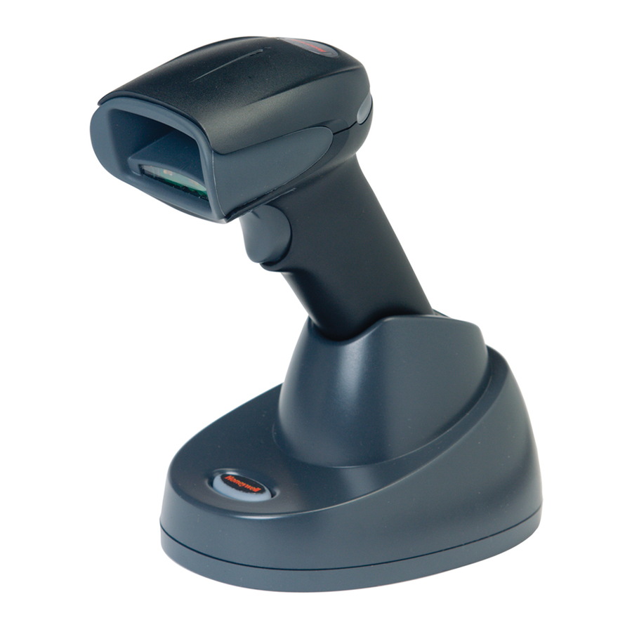
Honeywell Xenon 1900 User Manual
Area-imaging scanner
Hide thumbs
Also See for Xenon 1900:
- User manual (364 pages) ,
- Quick start manual (21 pages) ,
- User manual (288 pages)

Related Manuals for Honeywell Xenon 1900


Summary of Contents for Honeywell Xenon 1900
- Page 1 Xenon™ 1900/1910 Xenon™ 1902/1912 Granit™ 1910i/1911i ™ Area-Imaging Scanner User’s Guide...
- Page 2 Disclaimer Honeywell International Inc. (“HII”) reserves the right to make changes in speci- fications and other information contained in this document without prior notice, and the reader should in all cases consult HII to determine whether any such changes have been made. The information in this publication does not repre- sent a commitment on the part of HII.
- Page 3 The user may find the fol- lowing booklet helpful: “Something About Interference.” This is available at FCC local regional offices. Honeywell is not responsible for any radio or television interference caused by unauthorized modifications of this equip- ment or the substitution or attachment of connecting cables and equipment other than those specified by Honeywell.
- Page 4 Nijverheidsweg 9-13 5627 BT Eindhoven The Netherlands Honeywell International Inc. shall not be liable for use of our product with equipment (i.e., power supplies, personal computers, etc.) that is not CE marked and does not comply with the Low Voltage Directive.
- Page 5 This product has required the extraction and use of natural resources for its production. It may contain hazardous substances that could impact health and the environment, if not properly disposed. In order to avoid the dissemination of those substances in our environment and to diminish the pressure on the natural resources, we encourage you to use the appropriate take-back systems for product disposal.
- Page 6 Russia Gost-R certificate South Korea This product meets Korean agency approval. Taiwan If the following label is attached to your product, the product meets Taiwan agency approval: BSMI Standard: CNS13438, CNS14336 依據標準 : CNS13438, CNS14336 International LED Safety Statement LEDs have been tested and classified as “EXEMPT RISK GROUP” to the standard: IEC 62471:2006.
-
Page 7: Solids And Water Protection
Patents For patent information, please refer to www.honeywellaidc.com/patents. Solids and Water Protection The Xenon 1900 has a rating of IP41, immunity of foreign particles and dripping water. Warning To reduce the possibility of heat-related injuries, avoid touching sec- tions of the scanner that feel warm. - Page 8 Caution: Any changes or modifications made to this equipment not expressly approved by Honeywell may void the FCC authorization to operate this equipment. Use only shielded data cables with this system. This unit has been tested with cables less than 3 meters.
- Page 9 5627 BT Eindhoven The Netherlands Honeywell shall not be liable for use of our product with equipment (i.e., power supplies, personal computers, etc.) that is not CE marked and does not comply with the Low Voltage Directive. This equipment is intended for...
- Page 10 If you need more information on the collection, reuse, and recycling sys- tems, contact your local or regional waste administration. You may also contact your supplier for more information on the environ- mental performances of this product. Germany If your product is marked with the GS symbol, then the product has been issued a GS certificate showing compliance to EN 60950-1, Second Edition.
- Page 11 Japan Complies with Technical Regulations Conformity Certification of Specified Radio equipment. Korea This product meets Korean agency approval. Mexico Conforms to NOM-019. This product meets Cofetel approval. Russia Gost-R certificate. Taiwan If the following label is attached to your product, the product meets Taiwan agency approval: BSMI Standard: CNS13438, CNS14336 (Xenon 1902 only) 依據標準...
- Page 12 International LED Safety Statement Scanner LEDs have been tested and classified as “EXEMPT RISK GROUP” to the standard: IEC 62471:2006. Radio Technology Class II CB Scheme Certified to CB Scheme IEC 60950-1, Second Edition. Laser Safety Statement If the following label is attached to your product, it indicates the product contains a laser engine or laser aimer: LASER LIGHT.
- Page 13 The user may find the fol- lowing booklet helpful: “Something About Interference.” This is available at FCC local regional offices. Honeywell is not responsible for any radio or television interference caused by unauthorized modifications of this equip- ment or the substitution or attachment of connecting cables and equipment other than those specified by Honeywell.
- Page 14 Nijverheidsweg 9-13 5627 BT Eindhoven The Netherlands Honeywell International Inc. shall not be liable for use of our product with equipment (i.e., power supplies, personal computers, etc.) that is not CE marked and does not comply with the Low Voltage Directive.
- Page 15 Waste Electrical and Electronic Equipment Information Honeywell complies with Directive 2002/96/EC OF THE EUROPEAN PAR- LIAMENT AND OF THE COUNCIL of 27 January 2003 on waste electrical and electronic equipment (WEEE). This product has required the extraction and use of natural resources for its production.
- Page 16 CB Scheme Certified to CB Scheme IEC 60950-1, Second Edition. Laser Safety Statement If the following label is attached to your product, it indicates the product contains a laser engine or laser aimer: LASER LIGHT. DO NOT STARE INTO BEAM. CLASS 2 LASER PRODUCT. 1.0MW MAX OUTPUT: 650NM.
- Page 17 Caution: Any changes or modifications made to this equipment not expressly approved by Honeywell may void the FCC authorization to operate this equipment. Use only shielded data cables with this system. This unit has been tested with cables less than 3 meters.
- Page 18 5627 BT Eindhoven The Netherlands Honeywell shall not be liable for use of our product with equipment (i.e., power supplies, personal computers, etc.) that is not CE marked and does not comply with the Low Voltage Directive. This equipment is intended for...
- Page 19 If you need more information on the collection, reuse, and recycling sys- tems, contact your local or regional waste administration. You may also contact your supplier for more information on the environ- mental performances of this product. Australia/NZ C-Tick Statement Conforms to AS/NZS 3548 EMC requirements.
- Page 20 Laser Safety Statement If the following label is attached to your product, it indicates the product contains a laser engine or laser aimer: LASER LIGHT. DO NOT STARE INTO BEAM. CLASS 2 LASER PRODUCT. 1.0MW MAX OUTPUT: 650NM. IEC 60825-1 Ed 2 (2007). Complies with 21 CFR 1040.10 and 1040.11 except for deviations pursuant to Laser Notice No.
- Page 21 Required Safety Labels Xenon 1900/1910/1902/1912 Scanner Illumination output Part Compliance Number, Serial Label Number and location Revision Information location...
- Page 22 CCB01-010BT Base Part Number, Serial Number and Compliance Revision Label Information locations location...
- Page 23 Granit 1910i/1911i Scanner Illumination output Laser Label location Part Number, Serial Compliance Number and Revision label location Information location...
- Page 24 CCB02-100BT Base Compliance Label locations...
-
Page 25: Table Of Contents
USB PC or Macintosh Keyboard ......... 2-4 USB HID..............2-5 USB Serial..............2-5 CTS/RTS Emulation ..........2-5 ACK/NAK Mode............. 2-5 Remote MasterMind™ for USB........2-6 ® Verifone Ruby Terminal Default Settings ....2-6 ® Gilbarco Terminal Default Settings ......2-7 Honeywell Bioptic Aux Port Configuration....2-7... - Page 26 ® Datalogic™ Magellan Aux Port Configuration ...2-7 NCR Bioptic Aux Port Configuration ......2-8 Wincor Nixdorf Terminal Default Settings....2-8 Wincor Nixdorf Beetle™ Terminal Default Settings ..2-8 Keyboard Country Layout ..........2-9 Keyboard Style ............2-19 Keyboard Conversion ..........2-21 Control Character Output...........2-21 Keyboard Modifiers............2-22 RS232 Modifiers ............2-23 RS232 Baud Rate..........
- Page 27 Scanner Is Moved Back Into Range...... 3-4 Out of Range and Back into Range with Batch Mode On......... 3-4 Page Button ..............3-5 About the Battery ............3-5 Charging Information..........3-5 Battery Recommendations ........3-5 Proper Disposal of the Battery ......3-6 Beeper and LED Sequences and Meaning ....
- Page 28 Batch Mode Output Order........3-23 Total Records ............3-24 Delete Last Code ..........3-24 Clear All Codes ............ 3-24 Transmit Records to Host ........3-24 Batch Mode Transmit Delay ........ 3-25 Multiple Scanner Operation ........3-25 Scanner Name............3-26 Application Work Groups ...........3-27 Application Work Group Selection .......
- Page 29 Beeper Pitch – Error..........4-5 Beeper Duration – Good Read......4-5 LED – Good Read ..........4-5 Number of Beeps – Good Read ......4-6 Number of Beeps – Error ........4-6 Beeper Volume Max..........4-6 Good Read Delay..........4-7 User-Specified Good Read Delay ......
- Page 30 Require Output Sequence ........4-23 Output Sequence Editor ........4-23 To Add an Output Sequence ....... 4-24 Other Programming Selections......4-24 Output Sequence Editor ........4-26 Partial Sequence ..........4-26 Require Output Sequence ........4-27 Multiple Symbols............4-27 No Read..............4-28 Video Reverse ............4-28 Working Orientation ...........4-29 Chapter 5 - Data Editing Prefix/Suffix Overview..........5-1...
- Page 31 Miscellaneous Commands ........6-13 Data Formatter ............6-16 Data Format Non-Match Error Tone....6-17 Primary/Alternate Data Formats........ 6-18 Single Scan Data Format Change....... 6-18 Chapter 7 - Symbologies All Symbologies............7-2 Message Length Description........7-2 Codabar ..............7-3 Codabar Concatenation ........7-4 Code 39...............
- Page 32 ISBN Translate ............ 7-34 EAN/JAN-8 ..............7-35 MSI ................7-37 GS1 DataBar Omnidirectional ........7-39 GS1 DataBar Limited..........7-39 GS1 DataBar Expanded ..........7-40 Trioptic Code .............7-41 Codablock A ..............7-41 Codablock F...............7-43 PDF417..............7-44 MacroPDF417............7-45 MicroPDF417.............7-45 GS1 Composite Codes ..........7-46 UPC/EAN Version..........7-46 GS1 Emulation............7-47 TCIF Linked Code 39 (TLC39) ........7-48 QR Code..............7-49 QR Code Page ............
- Page 33 Image Ship - IMGSHP..........8-5 IMGSHP Modifiers..........8-5 Intelligent Signature Capture - IMGBOX ....8-14 Signature Capture Optimize ........ 8-14 IMGBOX Modifiers ..........8-15 RF Default Imaging Device ........8-19 Chapter 9 - Interface Keys Keyboard Function Relationships ....... 9-1 Supported Interface Keys..........
- Page 34 Chapter 12 - Product Specifications Xenon 1900/1910 Corded Scanner Product Specifications ............12-1 Xenon 1902/1912 Cordless Scanner Product Specifications ............12-2 Granit 1910i Industrial Corded Scanner Product Specifications ............12-3 Granit 1911i Industrial Cordless Scanner Product Specifications ............12-4 CCB01-010BT Charge Base Product Specifications ............12-6 CCB02-100BT Industrial Charge Base Product Specifications ............12-7...
- Page 35 Replacing Cables in Corded Scanners ..... 13-2 Replacing a Xenon Interface Cable..... 13-3 Replacing a Granit Interface Cable ..... 13-3 Replacing Cables and Batteries in Cordless Systems ..........13-4 Replacing an Interface Cable in a Base ....13-4 Changing a Xenon Scanner Battery....13-5 Changing a Granit Scanner Battery ....
-
Page 37: Chapter 1 - Getting Started
Product specifications, dimensions, warranty, and customer support information are also included. Honeywell bar code scanners are factory programmed for the most common terminal and communications settings. If you need to change these settings, programming is accomplished by scanning the bar codes in this guide. -
Page 38: Connecting The Device
Connecting the Device Connecting with USB A scanner or a cordless base can be connected to the USB port of a com- puter. Connect the appropriate interface cable to the device first, then to the computer. Corded Xenon Scanner USB Connection: Corded Granit Scanner USB Connection: 1 - 2... - Page 39 If you are connecting a Granit scanner, make sure the cable is pushed tightly into the scanner. Loosen the locking plate and slide it over the base of the cable connector to lock the cable in place. Tighten the screw. CCB01-010BT Base USB Connection: CCB02-100BT Base...
-
Page 40: Connecting With Keyboard Wedge
base sits flat on a horizontal surface. If you are connecting a CCB02- 100BT Base, see Mounting a CCB02-100BT Base on page 1-11. The scanner beeps. Verify the scanner or cordless base operation by scanning a bar code from the Sample Symbols in the back of this manual. - Page 41 Corded Granit Scanner Keyboard Wedge Connection: If you are connecting a Granit scanner, make sure the cable is pushed tightly into the scanner. Loosen the locking plate and slide it over the base of the cable connector to lock the cable in place. Tighten the screw.
- Page 42 CCB02-100BT Base Keyboard Wedge Connection: Note: The power supply must be ordered separately, if needed. If you are connecting a CCB01-010BT Base, make sure the cables are secured in the wireways in the bottom of the cordless base and the base sits flat on a horizontal surface.
-
Page 43: Connecting With Rs232 Serial Port
Connecting with RS232 Serial Port Turn off power to the terminal/computer. Connect the appropriate interface cable to the scanner. Note: For the scanner or cordless base to work properly, you must have the correct cable for your type of terminal/computer. Corded Xenon Scanner RS232 Serial Port Connection:... - Page 44 Corded Granit Scanner RS232 Serial Port Connection: If you are connecting a Granit scanner, make sure the cable is pushed tightly into the scanner. Loosen the locking plate and slide it over the base of the cable connector to lock the cable in place. Tighten the screw.
- Page 45 CCB02-100BT Base RS232 Serial Port Connection: Note: The power supply must be ordered separately, if needed. If you are connecting a CCB01-010BT Base, make sure the cables are secured in the wireways in the bottom of the cordless base and the base sits flat on a horizontal surface.
-
Page 46: Connecting With Rs485
Connecting with RS485 A Xenon scanner or cordless base can be connected for an IBM POS ter- minal interface. (This interface is not available in the Granit devices.) Connect the appropriate interface cable to the device, then to the com- puter. -
Page 47: Mounting A Ccb01-010Bt Charge Base
Make sure the cables are secured in the wireways in the bottom of the cordless base and the base sits flat on a horizontal surface. Turn the terminal/computer power back on. The scanner beeps. Verify the scanner or cordless base operation by scanning a bar code from the Sample Symbols in the back of this manual. - Page 48 The cables can also be routed up through the top of the base, crossing them over and securing the cables in the wireways. When routing the cables up through the top of the base, be sure to cross the cables over before placing in the wireways. If not, too much strain is placed on the cable connectors.
- Page 49 Use 30mm screws, appropriate for the mounting surface material, to mount the base securely. 2.51 in. 5.31 in. 2 in. 63.7mm 134.92mm 51.17mm 2.36 in. 60mm .84 in. 21.42mm 1 - 13...
-
Page 50: Reading Techniques
Reading Techniques The Xenon 1900/1902 scanners have a view finder that projects a bright red aiming beam that corresponds to the scanner’s horizontal field of view. The Xenon 1910/1912 and Granit 1910i/1911i scanners have an aiming pattern . The aiming beam or pattern should be centered over the bar code, but it can be positioned in any direction for a good read. -
Page 51: Menu Bar Code Security Settings
Menu Bar Code Security Settings Honeywell scanners are programmed by scanning menu bar codes or by send- ing serial commands to the scanner. If you want to restrict the ability to scan menu codes, you can use the Menu Bar Code Security settings. Please contact... -
Page 52: Resetting The Custom Defaults
Resetting the Custom Defaults If you want the custom default settings restored to your scanner, scan the Acti- vate Custom Defaults bar code below. This is the recommended default bar code for most users. It resets the scanner to the custom default settings. If there are no custom defaults, it will reset the scanner to the factory default set- tings. -
Page 53: Chapter 2 - Programming The Interface
Programming the Interface Introduction This chapter describes how to program your system for the desired interface. Programming the Interface - Plug and Play Plug and Play bar codes provide instant scanner set up for commonly used interfaces. Note: After you scan one of the codes, power cycle the host terminal to have the interface in effect. -
Page 54: Rs232 Serial Port
RS232 Serial Port The RS232 Interface bar code is used when connecting to the serial port of a PC or terminal. The following RS232 Interface bar code also programs a car- riage return (CR) and a line feed (LF) suffix, baud rate, and data format as indi- cated below. -
Page 55: Rs485 Packet Mode
Each bar code above also programs the following suffixes for each symbology: Symbology Suffix Symbology Suffix EAN 8 Code 39 00 0A 0B EAN 13 Interleaved 2 of 5 00 0D 0B UPC A Code 128 * 00 0A 0B UPC E Code 128 ** 00 18 0B... -
Page 56: Usb Ibm Surepos
USB IBM SurePos Scan one of the following “Plug and Play” codes to program the scanner for an IBM SurePos (USB handheld scanner) or IBM SurePos (USB tabletop scanner) interface. Note: After scanning one of these codes, you must power cycle the cash register. -
Page 57: Usb Hid
Scan the following code to program the scanner to emulate a regular RS232- based COM Port. If you are using a Microsoft® Windows® PC, you will need to download a driver from the Honeywell website (www.honeywellaidc.com). The driver will use the next available COM Port number. Apple® Macintosh comput- ers recognize the scanner as a USB CDC class device and automatically use a class driver. -
Page 58: Remote Mastermind™ For Usb
Remote MasterMind™ for USB When using a USB interface, you may wish to configure your scanner to com- municate with Remote MasterMind Scanner Management Software (ReM). Scan the ReM On bar code to communicate with ReM. To disable this capabil- ity, scan ReM Off. -
Page 59: Gilbarco ® Terminal Default Settings
Gilbarco Settings Honeywell Bioptic Aux Port Configuration Scan the following Plug and Play code to program the scanner for a Honeywell bioptic scanner auxiliary port configuration. This bar code sets the baud rate to 38400 bps and the data format to 8 data bits, no parity, 1 stop bit. -
Page 60: Ncr Bioptic Aux Port Configuration
NCR Bioptic Aux Port Configuration Scan the following Plug and Play code to program the scanner for an NCR biop- tic scanner auxiliary port configuration. The following prefixes are programmed for each symbology: Symbology Prefix Symbology Prefix UPC-A Code 39 UPC-E Interleaved 2 of 5 EAN-8... -
Page 61: Keyboard Country Layout
Wincor Nixdorf Beetle Settings Keyboard Country Layout Scan the appropriate country code below to program the keyboard layout for your country or language. As a general rule, the following characters are sup- ported, but need special care for countries other than the United States: @ | $ # { } [ ] = / ‘... - Page 62 Keyboard Countries (Continued) Bosnia Brazil Brazil (MS) Bulgaria (Cyrillic) Bulgaria (Latin) Canada (French legacy) Canada (French) Canada (Multilingual) 2 - 10...
- Page 63 Keyboard Countries (Continued) Croatia Czech Czech (Programmers) Czech (QWERTY) Czech (QWERTZ) Denmark Dutch (Netherlands) Estonia 2 - 11...
- Page 64 Keyboard Countries (Continued) Faroese Finland France Gaelic Germany Greek Greek (220 Latin) Greek (220) 2 - 12...
- Page 65 Keyboard Countries (Continued) Greek (319 Latin) Greek (319) Greek (Latin) Greek (MS) Greek (Polytonic) Hebrew Hungarian (101 key) Hungary Iceland 2 - 13...
- Page 66 Keyboard Countries (Continued) Irish Italian (142) Italy Japan ASCII Kazakh Kyrgyz (Cyrillic) Latin America Latvia 2 - 14...
- Page 67 Keyboard Countries (Continued) Latvia (QWERTY) Lithuania Lithuania (IBM) Macedonia Malta Mongolian (Cyrillic) Norway Poland 2 - 15...
- Page 68 Keyboard Countries (Continued) Polish (214) Polish (Programmers) Portugal Romania Russia Russian (MS) Russian (Typewriter) 2 - 16...
- Page 69 Keyboard Countries (Continued) Serbia (Cyrillic) Serbia (Latin) Slovakia Slovakia (QWERTY) Slovakia (QWERTZ) Slovenia Spain Spanish variation 2 - 17...
- Page 70 Keyboard Countries (Continued) Sweden Switzerland (French) Switzerland (German) Tatar Turkey F Turkey Q Ukrainian United Kingdom 2 - 18...
-
Page 71: Keyboard Style
Keyboard Countries (Continued) United States (Dvorak) United States (Dvorak left) United Stated (Dvorak right) United States (International) Uzbek (Cyrillic) Keyboard Style This programs keyboard styles, such as Caps Lock and Shift Lock. If you have used Keyboard Conversion settings, they will override any of the following Key- board Style settings. - Page 72 Caps Lock is used when you normally have the Caps Lock key on. Caps Lock Shift Lock is used when you normally have the Shift Lock key on (not common to U.S. keyboards). Shift Lock Automatic Caps Lock is used if you change the Caps Lock key on and off. The software tracks and reflects if you have Caps Lock on or off .
-
Page 73: Keyboard Conversion
Keyboard Conversion Alphabetic keyboard characters can be forced to be all upper case or all lower- case. So if you have the following bar code: “abc569GK,” you can make the out- put “ABC569GK” by scanning Convert All Characters to Upper Case, or to “abc569gk”... -
Page 74: Keyboard Modifiers
Keyboard Modifiers This modifies special keyboard features, such as CTRL+ ASCII codes and Turbo Mode. Control + X (Control + ASCII) Mode On: The scanner sends key combina- tions for ASCII control characters for values 00-1F. Windows is the preferred mode. -
Page 75: Rs232 Modifiers
Numeric Keypad Mode: Sends numeric characters as if entered from a numeric keypad. Default = Off Numeric Keypad Mode On * Numeric Keypad Mode Off Automatic Direct Connect Mode: This selection can be used if you have an IBM AT style terminal and the system is dropping characters. Default = Off Automatic Direct Connect Mode * Automatic Direct Connect Mode Off... - Page 76 1200 2400 4800 9600 19200 38400 57,600 * 115,200 2 - 24...
-
Page 77: Rs232 Word Length: Data Bits, Stop Bits, And Parity
RS232 Word Length: Data Bits, Stop Bits, and Parity Data Bits sets the word length at 7 or 8 bits of data per character. If an application requires only ASCII Hex characters 0 through 7F decimal (text, digits, and punctuation), select 7 data bits. For applications that require use of the full ASCII set, select 8 data bits per character. -
Page 78: Rs232 Receiver Time-Out
* 8 Data, 1 Stop, Parity None 8 Data, 1 Stop, Parity Odd 7 Data, 1 Stop, Parity Space 7 Data, 2 Stop, Parity Space 8 Data, 1 Stop, Parity Space 7 Data, 1 Stop, Parity Mark 7 Data, 2 Stop, Parity Mark 8 Data, 1 Stop, Parity Mark RS232 Receiver Time-Out The unit stays awake to receive data until the RS232 Receiver Time-Out... -
Page 79: Rs232 Handshaking
receiver. The receiver takes 300 milliseconds to completely come up. Change the RS232 receiver time-out by scanning the bar code below, then scanning digits from the inside back cover of this manual, then scanning Save. The range is 0 to 300 seconds. Default = 0 seconds (no time-out - always on). -
Page 80: Rs232 Timeout
RS232 Timeout When using Flow Control with Timeout, you must program the length of the delay you want to wait for CTS from the host. Set the length (in millisec- onds) for a timeout by scanning the bar code below, then setting the time- out (from 1-5100 milliseconds) by scanning digits from the inside back cover, then scanning Save. -
Page 81: Scanner To Bioptic Communication
ACK/NAK On * ACK/NAK Off Scanner to Bioptic Communication The following settings are used to set up communication between Honeywell scanners and bioptic scanners. Note: The scanner’s baud rate must be set to 38400 and the RS232 timeout must be set to 3000 in order to communicate with a bioptic scanner. See... -
Page 82: Scanner-Bioptic Ack/Nak Mode
Scanner-Bioptic ACK/NAK Mode Bioptic ACK/Nak On must be scanned so the scanner will wait for an ACK or NAK from a bioptic scanner after each packet is sent. The Scanner- Bioptic ACK/NAK Timeout (below) controls how long the scanner will wait for a response. -
Page 83: Chapter 3 - Cordless System Operation
Cordless System Operation Note: This chapter applies only to cordless scanning systems. It does not apply to corded scanners. How the Cordless Charge Base/Access Point Works A cordless charge base or an Access Point provide the link between the cord- less scanner and the host system. -
Page 84: Linking The Scanner To An Access Point
To determine if your cordless system is set up correctly, scan one of the sample bar codes in the back of this manual. If the scanner provides a single good read beep and the green LED lights, the scanner has successfully linked to the base. If using a Granit scanner, the scanner also vibrates. -
Page 85: Programming The Scanner And Base Or Access Point
been properly sent to the base or Access Point, the scanner issues an error indication. You must then check to see if the scanned data was received by the host system. Scanner reads code and gets ACK from base or Access Point Base or Access Point sends data to host Programming the Scanner and Base or Access Point... -
Page 86: System Conditions
2) provides a communication range of 33 feet (10m) between the scanner and base or Access Point, depending on the environment. The CCB02-100BT (Bluetooth Class 1) provides a communication range of 330 feet (100m) between the scanner and base or Access Point, depending on the environment. Flexible Power Management, page 3-18, for information about controlling this range. -
Page 87: Page Button
You will not hear a communication error tone in this mode, but you will hear a short buzz when you pull the trigger if the radio communication is not working. Once the radio connection is made, the scanner produces a series of beeps while the data is being transferred to the base or Access Point. -
Page 88: Proper Disposal Of The Battery
Caution: Use only Honeywell Li-ion battery packs, model number BAT- SCN01, rated 3.7 Vdc, 7.4Whr in this device. Use of any non- Honeywell battery may result in damage not covered by the warranty. Safety Precautions for Lithium Batteries •... -
Page 89: Beeper And Led Sequences And Meaning
Beeper and LED Sequences and Meaning The scanner contains LEDs on the rear of the unit that indicate linking status, decoding state, and battery condition. The base has LEDs on the top of the unit that indicate its power up, communication, and battery charge condition. The red LED = error;... -
Page 90: Scanner Led Sequences And Meaning
Scanner LED Sequences and Meaning Beeper Vibrate Cause Indication Indication Indication Normal Operation Red Flash None None Battery low Green Flash 1 beep None Successful communication or linking Red, blinking Razz or error None Failed communication tone Menu Operation Green Flash 2 beeps 2 vibrations Successful menu... -
Page 91: Base Power Communication Indicator
Green LED - Scanner Battery (base only, does not apply to Access Point) Green LED Charge Condition Battery not detected or charge suspended Slow flash, 1 second on, 1 second off Pre-charge and charging On continuously Charge complete Fast flash, 300 mSec on, 300 mSec off Charge Error Base Power Communication Indicator To display the power indicator on a base or an Access Point, scan the Base... -
Page 92: Paging
Off. If you want the scanner to shut down when in the base cradle, scan Shut Down Scanner in Cradle. Default = Scanning in Cradle On (for CCB01- 010BT) . Scanning in Cradle Off * Scanning in Cradle On Shut Down Scanner in Cradle Paging Paging Mode By default, the paging button on the base or Access Point pages the scan-... -
Page 93: Paging Pitch
Pitch Paging When you press the Page button on the base or Access Point, the scan- ners associated with that base or Access Point will begin beeping (see Page Button on page 3-5). You can set the pitch of the paging beep for each scanner by scanning one of the following bar codes. -
Page 94: Scanner Report
The number of beeps and LED flashes emitted by the CCB01-010BT base for an error condition can be programmed from 1 - 9. For example, if you program this option to have five error beeps, there will be five error beeps and five LED flashes in response to an error. -
Page 95: Scanner Modes
Scanner Modes Your scanner is capable of working in single scanner mode, multiple scanner mode, or with Bluetooth devices other than the charge base or Access Point. Charge Only Mode There may be times when you want to charge your scanner, but not link to the base. -
Page 96: Unlinking The Scanner
Locked Link Mode - Single Scanner If you link a scanner to a base or an Access Point using the Locked Link Mode, other scanners are blocked from being linked if they are inadvertently placed into the base, or if the Access Point linking bar code is scanned. -
Page 97: Override Locked Scanner
Override Locked Scanner If you need to replace a broken or lost scanner that is linked to a base or an Access Point, scan the Override Locked Scanner bar code below with a new scanner and place that scanner in the base, or scan the Access Point linking bar code. -
Page 98: Scanner Power Time-Out Timer
The sounds are as follows: Setting Sound 3 long beeps, medium pitch 3 long beeps, high pitch 4 short beeps, medium pitch 4 short beeps, high pitch single chirps, medium pitch 2 chirps, then 1 chirp, medium pitch single chirps, high pitch 2 chirps, then 1 chirp, high pitch Base Alarm Type Note:... - Page 99 If there are no trigger pulls during the timer interval, the scanner goes into power down mode. Whenever the trigger is enabled, the timer is reset. If the scanner is placed in the charge base cradle and the battery is in the process of being charged, the scanner will not go into power down mode.
-
Page 100: Flexible Power Management
Flexible Power Management If you are experiencing network performance issues, and suspect the scanner is interfering with other devices, you can turn down the power output of the scan- ner. This reduces the range between the scanner and a base or an Access Point as shown in the following illustration: 802.11 1902... -
Page 101: Batch Mode
Reset Scanner and Base/Access Point Once the power level is set, you must scan the Reset Base bar code and wait for the scanner to unlink and relink to a base or an Access Point. Once that is done, scan the Reset Scanner bar code and wait for the base or Access Point to unlink and relink to the scanner. -
Page 102: Batch Mode Beep
Default = Batch Mode Off. * Batch Mode Off Automatic Batch Mode Inventory Batch Mode Persistent Batch Mode Batch Mode Beep When scanning in Inventory Batch Mode (page 3-20), the scanner beeps every time a bar code is scanned. If using a Granit scanner, it also vibrates. -
Page 103: Batch Mode Quantity
RAM Storage: The scanner will not power down while it contains data that has not been transmitted to the base or Access Point, even if it reaches a power down timeout. However, if the scanner runs out of battery power, it will power down and the data will be lost. - Page 104 Example: Add a quantity of 5 for the last item scanned. Scan the item's bar code. Scan the quantity 5 bar code. Example: Add a quantity of 1,500 for the last item scanned. Scan the item's bar code. Scan the quantity 1 bar code. Scan the quantity 5 bar code.
-
Page 105: Batch Mode Output Order
Batch Mode Output Order When batch data is transmitted, select whether you want that data sent as FIFO (first-in first-out), or LIFO (last-in first-out). Default = Batch Mode FIFO. * Batch Mode FIFO Batch Mode LIFO 3 - 23... -
Page 106: Total Records
Total Records If you wish to output the total number of bar codes scanned when in Batch Mode, scan Total Records. Total Records Delete Last Code If you want to delete the last bar code scanned when in Batch Mode, scan Delete Last Code. -
Page 107: Batch Mode Transmit Delay
Batch Mode Transmit Delay Sometimes when accumulated scans are sent to the host system, the transmission of those scans is too fast for the application to process. To program a transmit delay between accumulated scans, scan one of the fol- lowing delays. -
Page 108: Scanner Name
To put the scanner in multiple scanner mode, scan the bar code below. Once you scan this bar code, the scanner is unlinked from the base or Access Point and must either be placed into the base, or you must scan the Access Point link- ing bar code in order to relink. -
Page 109: Application Work Groups
0004 0005 0006 0007 Reset You may also scan the Scanner Name bar code below and scan a number for the scanner name. For example, if you wanted to name the linked scanner “312,” you would scan the bar code below, scan the 3, 1, and 2 bar codes on the Programming Chart inside the back cover of this manual, then scan Save. -
Page 110: Application Work Group Selection
Honeywell’s online configuration tool, EZConfig-Scanning (page 10-2), makes it easy for you to program your system for use with multiple scanners and multiple work groups. -
Page 111: Resetting The Factory Defaults: All Application Work Groups
Group 5 Group 6 Resetting the Factory Defaults: All Application Work Groups The following bar code defaults all of the work groups to the factory default set- tings. PAPDFT& Factory Default Settings: All Work Groups To see what the factory default settings are, refer to the table of Menu Commands, beginning on page 11-5. -
Page 112: Resetting The Custom Defaults: All Application Work Groups
The scanner can be used either with the charge base, an Access Point, or with other Bluetooth devices. Those devices include personal computers, laptops, PDAs, and Honeywell mobility systems devices. Bluetooth HID Keyboard Connect Your scanner can be paired with Bluetooth-capable devices, such as iPads, smart phones, and laptops, so that scanned data appears on your device screen as though it was entered on the keyboard. - Page 113 Once your host device has located the scanner, select the scanner name. The host generates and displays a random PIN that must be scanned within 60 seconds. You must quickly scan Bluetooth PIN Code, then the numbers below, then Save. Bluetooth PIN Code 3 - 31...
-
Page 114: Bluetooth Hid Keyboard Disconnect
Save Bluetooth HID Keyboard Disconnect If your scanner has been connected directly to an iPad, smart phone, or laptop using Bluetooth HID Keyboard Connect (page 3-30), you must dis- connect it in order to once again communicate with the base or Access Point. -
Page 115: Pdas/Mobility Systems Devices
Non-Base BT Connection PDAs/Mobility Systems Devices You may also use the scanner with a PDA or a Honeywell Mobility Systems device. Scan the bar code below and follow the instructions supplied with your Bluetooth device to locate the scanner, and connect with it. -
Page 116: Auto Reconnect Mode
Auto Reconnect Mode Auto Reconnect controls whether or not the scanner automatically begins the relink process when a loss of connection is detected. When the Auto Reconnect On bar code is scanned, the scanner begins the relink process immediately, without user intervention. Default = Auto Reconnect On. * Auto Reconnect On Auto Reconnect Off Note: If you are connecting to a Bluetooth Interface Module, set Auto... -
Page 117: Maximum Link Attempts
Event Auto Reconnect On Auto Reconnect Off Scanner power Trigger must be pulled, Access Point linking bar down due to Power code must be scanned, or the scanner must be Time-Out Timer placed in the base unit to relink. setting (see page 4- (Note: scanner relinks on power up, but powers on due to one of the above actions.) -
Page 118: Relink Time-Out
Relink Time-Out Relink Time-Out controls the idle time between relink attempts. An attempt to link a scanner to a base or an Access Point typically lasts up to 5 sec- onds. This is the time when the scanner is actually attempting a contact . Relink Time-Out controls the amount of time, in seconds, that elapses between the end of one connection attempt and the start of the next. -
Page 119: Host Acknowledgment
Auto Reconnect Mode set to 1 Maximum Link Attempts set to 0 Relink Time-Out set to 10 Scanner Power Time-Out Timer set to 1800 Note: See Scanner Power Time-Out Timer on page 3-16. The scanner attempts to connect to the base or Access Point every 15 sec- onds, measured from one attempt start to the next attempt start. - Page 120 Example: A good read beep is required for any item on file, but a razz or error tone is required if the item is not on file. In this case, [ESC]7, is sent to the host for an on-file product [ESC]8,[ESC]8, is sent to the host for a not-on-file product When a bar code is scanned, the scanner enters a timeout period until either the host ACK sequence is received, or the timeout expires (in 10 seconds, by...
- Page 121 Command Action [ESC] 2, The green LED illuminates for 2 seconds followed by a pause. [ESC] 3, The green LED illuminates for 5 seconds followed by a pause. [ESC] 4, Emits a beep at a low pitch. [ESC] 5, Emits a beep at a medium pitch. [ESC] 6, Emits a beep at a high pitch.
- Page 122 3 - 40...
-
Page 123: Chapter 4 - Input/Output Settings
Input/Output Settings Power Up Beeper Note: This feature does not apply to the CCB02-100BT base. The scanner can be programmed to beep when it’s powered up. If you are using a cordless system, the base can also be programmed to beep when it is powered up. -
Page 124: Beep On Bel Character
Beep on BEL Character You may wish to force the scanner to beep upon a command sent from the host. If you scan the Beep on BEL On bar code below, the scanner will beep every time a BEL character is received from the host. Default = Beep on BEL Off. *Beep on BEL Off Beep on BEL On Trigger Click... -
Page 125: Beeper Volume - Good Read
Beeper Volume – Good Read The beeper volume codes modify the volume of the beep the scanner emits on a good read. Default = High. Medium * High Beeper Pitch – Good Read The beeper pitch codes modify the pitch (frequency) of the beep the scan- ner emits on a good read. -
Page 126: Vibrate - Good Read
* Medium - Granit (3200 Hz) High (4200 Hz) Vibrate – Good Read Note: Vibration settings apply only to Granit Devices. The scanner vibrates once when a bar code is successfully read, and twice when a programming bar code is successfully read. When a programming bar code is unsuccessful, the scanner emits one long vibration (2 times the Vibrate Duration length). -
Page 127: Beeper Pitch - Error
Beeper Pitch – Error The beeper pitch codes modify the pitch (frequency) of the sound the scan- ner emits when there is a bad read or error. Default = Razz. * Razz (250 Hz) Medium (3250 Hz) High (4200 Hz) Beeper Duration –... -
Page 128: Number Of Beeps - Good Read
Number of Beeps – Good Read The number of beeps of a good read can be programmed from 1 - 9. The same number of beeps will be applied to the beeper and LED in response to a good read. For example, if you program this option to have five beeps, there will be five beeps and five LED flashes in response to a good read. -
Page 129: Good Read Delay
Good Read Delay This sets the minimum amount of time before the scanner can read another bar code. Default = 0 ms (No Delay). * No Delay Short Delay (500 ms) Medium Delay (1,000 ms) Long Delay (1,500 ms) User-Specified Good Read Delay If you want to set your own length for the good read delay, scan the bar code below, then set the delay (from 0 - 30,000 milliseconds) by scanning digits from the inside back cover, then scanning Save. -
Page 130: Led Illumination - Manual Trigger
less range than Normal mode. Enhanced mode is best used when you require a very fast scan speed and don’t require a long working range. Default = Man- ual Trigger-Normal. * Manual Trigger - Normal Manual Trigger - Enhanced LED Illumination - Manual Trigger If you wish to set the illumination LED brightness, scan one of the bar codes below. -
Page 131: Serial Trigger Mode
Serial Trigger Mode You can activate the scanner either by pressing the trigger, or using a serial trig- ger command (see Trigger Commands on page 11-4). When in serial mode, the scanner scans until a bar code has been read or until the deactivate com- mand is sent. -
Page 132: Led Illumination - Presentation Mode
LED Illumination - Presentation Mode If you wish to set the illumination LED brightness, scan one of the bar codes below. This sets the LED illumination for the scanner when it is in Presentation Mode. (If the scanner is triggered manually, the LED illumina- tion will switch to the setting for a manual trigger. -
Page 133: Presentation Sensitivity
Presentation Sensitivity Presentation Sensitivity is a numeric range that increases or decreases the scanner's reaction time to bar code presentation. To set the sensitivity, scan the Sensitivity bar code, then scan the degree of sensitivity (from 0- 20) from the inside back cover, and Save. 0 is the most sensitive setting, and 20 is the least sensitive. - Page 134 In the example below, the white box is the centering window. The centering window has been set to 20% left, 30% right, 8% top, and 25% bottom. Since Bar Code 1 passes through the centering window, it will be read. Bar Code 2 does not pass through the centering window, so it will not be read.
- Page 135 * Presentation Centering Off Top of Presentation Centering Window Bottom of Presentation Centering Window Left of Presentation Centering Window Right of Presentation Centering Window 4 - 13...
-
Page 136: In-Stand Sensor Mode
In-Stand Sensor Mode Note: The In-Stand Sensor feature only applies to Xenon products. This feature senses when the scanner is removed from the stand and tells it to begin manual triggering. When Sensor On is enabled, the scanner defaults to Streaming Presentation Mode when it is in the stand, and to Manual Trigger Mode when it is removed from the stand. -
Page 137: Streaming Presentation™ Mode
Streaming Presentation ™ Mode When in Streaming Presentation mode, the scanner’s aimer goes out after a short time, but the scan illumination remains on all the time to continuously search for bar codes. Two modes are available, Normal and Enhanced. Nor- mal mode offers good scan speed and the longest working ranges (depth of field). -
Page 138: Mobile Phone Read Mode
Mobile Phone Read Mode When this mode is selected, your scanner is optimized to read bar codes from mobile phone or other LED displays. However, the speed of scanning printed bar codes may be slightly lower when this mode is enabled. You can enable Mobile Phone Reading for either a hand held device, or for a hands-free (pre- sentation) application. -
Page 139: User-Specified Reread Delay
Use shorter delays in applications where repetitive bar code scanning is required. Reread Delay only works when in a Presentation Mode (see page 4- 9). Default = Medium. Short (500 ms) * Medium (750 ms) Long (1000 ms) Extra Long (2000 ms) User-Specified Reread Delay If you want to set your own length for the reread delay, scan the bar code below, then set the delay (from 0-30,000 milliseconds) by scanning digits from the... -
Page 140: Illumination Lights
Illumination Lights If you want the illumination lights on while reading a bar code, scan the Lights On bar code, below. However, if you want to turn just the lights off, scan the Lights Off bar code. Default = Lights On. Note: This setting does not affect the aimer light. -
Page 141: Scanner Time-Out
Scanner Time-Out Note: Scanner Time-Out applies only to corded scanners. It does not apply to cordless systems. Scanner Time-Out powers down the scanner after the unit has been idle for the specified time. To prevent the scanner from powering down, set this time-out to 0, or no timer. - Page 142 In the example below, the white box is the centering window. The centering window has been set to 20% left, 30% right, 8% top, and 25% bottom. Since Bar Code 1 passes through the centering window, it will be read. Bar Code 2 does not pass through the centering window, so it will not be read.
-
Page 143: Preferred Symbology
* Centering Off Top of Centering Window Bottom of Centering Window Left of Centering Window Right of Centering Window Preferred Symbology The scanner can be programmed to specify one symbology as a higher priority over other symbologies in situations where both bar code symbologies appear on the same label, but the lower priority symbology cannot be disabled. -
Page 144: High Priority Symbology
Default = Scan a bar code below to enable or disable Preferred Symbology. Preferred Symbology Off. Preferred Symbology On * Preferred Symbology Off High Priority Symbology To specify the high priority symbology, scan the High Priority Symbology bar code below. On the Symbology Charts on page A-1, find the symbol- ogy you want to set as high priority. -
Page 145: Preferred Symbology Default
bar code has been encountered. Scan the bar code below, then set the delay (from 1-3,000 milliseconds) by scanning digits from the inside back cover, then scanning Save. Default = 500 ms. Preferred Symbology Time-out Preferred Symbology Default Scan the bar code below to set all Preferred Symbology entries to their default values. -
Page 146: To Add An Output Sequence
To Add an Output Sequence Scan the Enter Seq uence symbol (see Require Output Sequence, page 4-27). Code I.D. On the Symbology Charts on page A-1, find the symbology to which you want to apply the output sequence format. Locate the Hex value for that symbology and scan the 2 digit hex value from the Programming Chart (inside back cover). - Page 147 Output Sequence Example In this example, you are scanning Code 93, Code 128, and Code 39 bar codes, but you want the scanner to output Code 39 1st, Code 128 2nd, and Code 93 3rd, as shown below. Note: Code 93 must be enabled to use this example. A - Code 39 B - Code 128 C - Code 93...
-
Page 148: Output Sequence Editor
SEQBLKsequence editor start command code identifier for Code 39 0012 A - Code 39 sample length (11) plus CR suffix (1) = 12 start character match for Code 39, 41h = “A” termination string for first code code identifier for Code 128 0013 B - Code 128 sample length (12) plus CR suffix (1) = 13 start character match for Code 128, 42h = “B”... -
Page 149: Require Output Sequence
Require Output Sequence When an output sequence is Required, all output data must conform to an edited sequence or the scanner will not transmit the output data to the host device. When it’s On/Not Required, the scanner will attempt to get the output data to conform to an edited sequence but, if it cannot, the scanner transmits all output data to the host device as is. -
Page 150: No Read
No Read With No Read turned On, the scanner notifies you if a code cannot be read. If using an EZConfig-Scanning Tool Scan Data Window (see page 10-3), an “NR” appears when a code cannot be read. If No Read is turned Off, the “NR” will not appear. -
Page 151: Working Orientation
Working Orientation Some bar codes are direction-sensitive. For example, KIX codes and OCR can misread when scanned sideways or upside down. Use the working orientation settings if your direction-sensitive codes will not usually be presented upright to the scanner. Default = Upright. Upright: Vertical, Top to Bottom: (Rotate CW 90°) - Page 152 4 - 30...
-
Page 153: Chapter 5 - Data Editing
Data Editing Prefix/Suffix Overview When a bar code is scanned, additional information is sent to the host computer along with the bar code data. This group of bar code data and additional, user-defined data is called a “message string.” The selections in this section are used to build the user-defined data into the message string. -
Page 154: To Clear One Or All Prefixes Or Suffixes
symbology to which you want to apply the prefix or suffix. For example, for Code 128, Code ID is “j” and Hex ID is “6A”. Step 3. Scan the 2 hex digits from the Programming Chart inside the back cover of this manual or scan 9, 9 for all symbologies. Step 4. -
Page 155: To Add A Carriage Return Suffix To All Symbologies
Step 1. Scan the Clear One Prefix or Clear One Suffix symbol. Step 2. Determine the 2 digit Hex value from the Symbology Chart (included in the Symbology Charts, beginning on page A-1) for the symbology from which you want to clear the prefix or suffix. Step 3. -
Page 156: Function Code Transmit
Clear One Suffix Clear All Suffixes Function Code Transmit When this selection is enabled and function codes are contained within the scanned data, the scanner transmits the function code to the terminal. Charts of these function codes are provided in Supported Interface Keys starting on page... -
Page 157: Intercharacter Delay
Intercharacter Delay An intercharacter delay of up to 5000 milliseconds (in 5ms increments) may be placed between the transmission of each character of scanned data. Scan the Intercharacter Delay bar code below, then scan the number of 5ms delays, and the Save bar code using the Programming Chart inside the back cover of this manual. -
Page 158: Interfunction Delay
Interfunction Delay An interfunction delay of up to 5000 milliseconds (in 5ms increments) may be placed between the transmission of each control character in the mes- sage string. Scan the Interfunction Delay bar code below, then scan the number of 5ms delays, and the Save bar code using the Programming Chart inside the back cover of this manual. -
Page 159: Chapter 6 - Data Formatting
Data Formatting Data Format Editor Introduction You may use the Data Format Editor to change the scanner’s output. For exam- ple, you can use the Data Format Editor to insert characters at certain points in bar code data as it is scanned. The selections in the following pages are used only if you wish to alter the output. - Page 160 you are programming. (See Primary/Alternate Data Formats on page 6-18 for further information.) Step 3. Terminal Type Refer to Terminal ID Table (page 6-4) and locate the Terminal ID number for your PC. Scan three numeric bar codes on the inside back cover to program the scanner for your terminal ID (you must enter 3 digits).
-
Page 161: Other Programming Selections
Discard Other Programming Selections Clear One Data Format This deletes one data format for one symbology. If you are clearing the primary format, scan 0 from the Programming Chart inside the back cover of this manual. If you are clearing an alternate format, scan 1, 2, or 3, depending on the format you are clearing. -
Page 162: Terminal Id Table
Terminal ID Table Terminal Model(s) Terminal ID PC keyboard (HID) Mac Keyboard PC Keyboard (Japanese) Serial (COM driver required) HID POS USB SurePOS Handheld USB SurePOS Tabletop Serial RS232 TTL RS232 True RS485 (IBM-HHBCR 1+2, 46xx) Keyboard PS2 compatibles AT compatibles Data Format Editor Commands When working with the Data Format Editor, a virtual cursor is moved along your input data string. - Page 163 F2 Example: Send a number of characters Send the first 10 characters from the bar code above, followed by a carriage return. Command string: F2100D F2 is the “Send a number of characters” command 10 is the number of characters to send 0D is the hex value for a CR The data is output as: 1234567890 F2 and F1 Example: Split characters into 2 lines...
-
Page 164
44 is the hex value for a 'D” 0D is the hex value for a CR The data is output as: 1234567890ABC
Send all characters up to a string B9 Include in the output message all characters from the input message, starting with the character at the current cursor position and continuing to, but not including, the search string “s...s.”... - Page 165 E9 and F4 Example: Send all but the last characters, followed by 2 tabs Send all characters except for the last 8 from the bar code above, fol- lowed by 2 tabs. Command string: E908F40902 E9 is the “Send all but the last characters” command 08 is the number of characters at the end to ignore F4 is the “Insert a character multiple times”...
-
Page 166
The data is output as: 1234567890**ABCDEFGHIJ
Insert symbology name B3 Insert the name of the bar code’s symbology in the output message, without moving the cursor. Only symbologies with a Honeywell ID are included (see Symbology Charts on page A-1). Refer to the... -
Page 167: Move Commands
Insert key strokes B5 Insert a key stroke or combination of key strokes. Key strokes are dependent on your keyboard (see Unicode Key Maps on page A-13). Any key can be inserted, including arrows and functions. Syntax = B5xxssnn where xx is the number of keys pressed (without key modifiers), ss is the key modifier from the table below, and nn is the key number from the Unicode Key... -
Page 168: Search Commands
F1 is the “Send all characters” command 0D is the hex value for a CR The data is output as: 4567890ABCDEFGHIJMove the cursor backward a number of characters F6 Move the cursor back “nn” characters from current cursor position. Syntax = F6nn where nn is the numeric value (00-99) for the number of characters the cursor should be moved back. - Page 169 F8 Example: Send bar code data that starts after a particular character Search for the letter “D” in bar codes and send all the data that follows, including the “D.” Using the bar code above: Command string: F844F10D F8 is the “Search forward for a character” command 44 is the hex value for “D”...
-
Page 170
48 is the hex value for “H” F1 is the “Send all characters” command 0D is the hex value for a CR The data is output as: FGHIJ
Search backward for a string B1 Search backward for “s” string from the current cursor position, leaving cursor pointing to “s”... -
Page 171: Miscellaneous Commands
Miscellaneous Commands Suppress characters FB Suppress all occurrences of up to 15 different characters, starting at the current cursor position, as the cursor is advanced by other commands. When the FC command is encountered, the suppress function is terminated. The cursor is not moved by the FB command. Syntax = FBnnxxyy . - Page 172 If the bar code has characters that the host application does not want included, you can use the E4 command to replace those characters with something else. In this example, you will replace the zeroes in the bar code above with carriage returns. Command string: E402300DF10D E4 is the “Replace characters”...
-
Page 173
EC is the “Check for a number” command F1 is the “Send all characters” command 0D is the hex value for a CR If this bar code is read, the format fails. If this bar code is read: the data is output as: 1234AB
... -
Page 174: Data Formatter
Discard Data B8 Discards types of data. For example, you may want to discard Code 128 bar codes that begin with the letter A. In step 4 (page 6-2), select 6A (for Code 128), and in step 5, select 9999 (for all lengths). Enter FE41B8 to compare and discard Code 128 bar codes that begin with the letter A. -
Page 175: Data Format Non-Match Error Tone
Choose one of the following options. Default = Data Formatter On, Not Required, Keep Prefix/Suffix. * Data Formatter On, Not Required, Keep Prefix/Suffix Data Formatter On, Not Required, Drop Prefix/Suffix Data Format Required, Keep Prefix/Suffix Data Format Required, Drop Prefix/Suffix Data Format Non-Match Error Tone When a bar code is encountered that doesn’t match your required data for- mat, the scanner normally generates an error tone. -
Page 176: Primary/Alternate Data Formats
will sound. If you wish to hear the error tone when a non-matching bar code is found, scan the Data Format Non-Match Error Tone On bar code. Default = Data Format Non-Match Error Tone On . * Data Format Non-Match Error Tone On Data Format Non-Match Error Tone Off... - Page 177 For example, you may have set your device to the data format you saved as Data Format 3. You can switch to Data Format 1 for a single trigger pull by scanning the Single Scan-Data Format 1 bar code below. The next bar code that is scanned uses Data Format 1, then reverts back to Data Format Single Scan-Primary Data Format...
- Page 178 6 - 20...
- Page 179 Symbologies This programming section contains the following menu selections. Refer to Chapter 11 for settings and defaults. • All Symbologies • Interleaved 2 of 5 • Aztec Code • Korea Post • China Post (Hong Kong 2 of 5) • Matrix 2 of 5 •...
-
Page 180: All Symbologies
All Symbologies If you want to decode all the symbologies allowable for your scanner, scan the All Symbologies On code. If on the other hand, you want to decode only a particular symbology, scan All Symbologies Off followed by the On symbol for that particular symbology. -
Page 181: Codabar
CodabarCodabar On/Off * On Codabar Start/Stop Characters Start/Stop characters identify the leading and trailing ends of the bar code. You may either transmit, or not transmit Start/Stop characters. Default = Don’t Transmit . Transmit * Don’t Transmit Codabar Check Character Codabar check characters are created using different “modulos.”... -
Page 182: Codabar Concatenation
When Check Character is set to Validate, but Don’t Transmit , the unit will only read Codabar bar codes printed with a check character, but will not transmit the check character with the scanned data. * No Check Character Validate Modulo 16, but Don’t Transmit Validate Modulo 16 and Transmit... -
Page 183: Codabar Message Length
Codabar Message Length Scan the bar codes below to change the message length. Refer to Message Length Description (page 7-2) for additional information. Mini- mum and Maximum lengths = 2-60. Minimum Default = 4, Maximum Default = 60. Minimum Message Length Maximum Message Length 7 - 5... -
Page 184: Code 39
Code 39 < Default All Code 39 Settings > Code 39 On/Off * On Code 39 Start/Stop Characters Start/Stop characters identify the leading and trailing ends of the bar code. You may either transmit, or not transmit Start/Stop characters. Default = Don’t Transmit. -
Page 185: Code 39 Message Length
When Check Character is set to Validate and Transmit, the scanner only reads Code 39 bar codes printed with a check character, and will transmit this character at the end of the scanned data. Default = No Check Charac- ter. * No Check Character Validate, but Don’t Transmit Validate and Transmit... -
Page 186: Code 32 Pharmaceutical (Paraf)
acter(s), it buffers Code 39 bar codes until it reads a Code 39 bar code that does not have the append trigger. The data is then transmitted in the order in which the bar codes were read (FIFO). Default = Off. * Off Code 32 Pharmaceutical (PARAF) Code 32 Pharmaceutical is a form of the Code 39 symbology used by Ital-... -
Page 187: Full Ascii
Full ASCII If Full ASCII Code 39 decoding is enabled, certain character pairs within the bar code symbol will be interpreted as a single character. For example: $V will be decoded as the ASCII character SYN, and /C will be decoded as the ASCII character #. -
Page 188: Interleaved 2 Of 5
10), and scan the value and the Save bar code from the Programming Chart on the inside the back cover of this manual. The data characters should then appear properly. Code 39 Code Page Interleaved 2 of 5 < Default All Interleaved 2 of 5 Settings > Interleaved 2 of 5 On/Off * On Check Digit... -
Page 189: Interleaved 2 Of 5 Message Length
When Check Digit is set to Validate and Transmit, the scanner only reads Interleaved 2 of 5 bar codes printed with a check digit, and will transmit this digit at the end of the scanned data. Default = No Check Digit. * No Check Digit Validate, but Don’t Transmit Validate and Transmit... -
Page 190: Nec 2 Of 5
NEC 2 of 5 < Default All NEC 2 of 5 Settings > NEC 2 of 5 On/Off * On Check Digit No Check Digit indicates that the scanner reads and transmits bar code data with or without a check digit. When Check Digit is set to Validate, but Don’t Transmit, the unit only reads NEC 2 of 5 bar codes printed with a check digit, but will not transmit the check digit with the scanned data. - Page 191 NEC 2 of 5 Message Length Scan the bar codes below to change the message length. Refer to Message Length Description (page 7-2) for additional information. Mini- mum and Maximum lengths = 2-80. Minimum Default = 4, Maximum Default = 80. Minimum Message Length Maximum Message Length 7 - 13...
-
Page 192: Code 93
Code 93 < Default All Code 93 Settings > Code 93 On/Off * On Code 93 Message Length Scan the bar codes below to change the message length. Refer to Message Length Description (page 7-2) for additional information. Mini- mum and Maximum lengths = 0-80. Minimum Default = 0, Maximum Default = 80. -
Page 193: Code 93 Code Page
which the bar codes are read, deleting the first space from each. The scanner transmits the appended data when it reads a Code 93 bar code that starts with a character other than a space. Default = Off. * Off Code 93 Code Page Code pages define the mapping of character codes to characters. -
Page 194: Straight 2 Of 5 Industrial (Three-Bar Start/Stop)
Straight 2 of 5 Industrial (three-bar start/stop)Straight 2 of 5 Industrial On/Off * Off Straight 2 of 5 Industrial Message Length Scan the bar codes below to change the message length. Refer to Message Length Description (page 7-2) for additional information. -
Page 195: Straight 2 Of 5 Iata (Two-Bar Start/Stop)
Straight 2 of 5 IATA (two-bar start/stop)Straight 2 of 5 IATA On/Off * Off Straight 2 of 5 IATA Message Length Scan the bar codes below to change the message length. Refer to Message Length Description (page 7-2) for additional information. -
Page 196: Matrix 2 Of 5
Matrix 2 of 5Matrix 2 of 5 On/Off * Off Matrix 2 of 5 Message Length Scan the bar codes below to change the message length. Refer to Message Length Description (page 7-2) for additional information. Mini- mum and Maximum lengths = 1-80. -
Page 197: Code 11
Code 11Code 11 On/Off * Off Check Digits Required This option sets whether 1 or 2 check digits are required with Code 11 bar codes. Default = Two Check Digits. One Check Digit * Two Check Digits 7 - 19... -
Page 198: Code 128
Code 11 Message Length Scan the bar codes below to change the message length. Refer to Message Length Description (page 7-2) for additional information. Mini- mum and Maximum lengths = 1-80. Minimum Default = 4, Maximum Default = 80. Minimum Message Length Maximum Message Length Code 128... -
Page 199: Code 128 Message Length
that supports concatenation of neighboring symbols, and 4) the standard layout for bar codes on a blood product label. Use the bar codes below to turn concatenation on or off. Default =Off. * Off Code 128 Message Length Scan the bar codes below to change the message length. Refer to Message Length Description (page 7-2) for additional information. -
Page 200: Code 128 Code Page
Code 128 Code Page Code pages define the mapping of character codes to characters. If the data received does not display with the proper characters, it may be because the bar code being scanned was created using a code page that is different from the one the host program is expecting. -
Page 201: Gs1-128
GS1-128GS1-128 On/Off * On GS1-128 Message Length Scan the bar codes below to change the message length. Refer to Message Length Description (page 7-2) for additional information. Mini- mum and Maximum lengths = 1-80. Minimum Default = 1, Maximum Default = 80. -
Page 202: Telepen
TelepenTelepen On/Off * Off Telepen Output Using AIM Telepen Output, the scanner reads symbols with start/stop pat- tern 1 and decodes them as standard full ASCII (start/stop pattern 1). When Original Telepen Output is selected, the scanner reads symbols with start/stop pattern 1 and decodes them as compressed numeric with optional full ASCII (start/stop pattern 2). -
Page 203: Upc-A
Telepen Message Length Scan the bar codes below to change the message length. Refer to Message Length Description (page 7-2) for additional information. Mini- mum and Maximum lengths = 1-60. Minimum Default = 1, Maximum Default = 60. Minimum Message Length Maximum Message Length UPC-A... - Page 204 UPC-A Check Digit This selection allows you to specify whether the check digit should be transmitted at the end of the scanned data or not. Default = On . * On UPC-A Number System The numeric system digit of a U.P.C. symbol is normally transmitted at the beginning of the scanned data, but the unit can be programmed so it will not transmit it.
-
Page 205: Upc-A/Ean-13
UPC-A Addenda Required When Req uired is scanned, the scanner will only read UPC-A bar codes that have addenda. You must then turn on a 2 or 5 digit addenda listed on page 7-26. Default = Not Required. Required * Not Required UPC-A Addenda Separator When this feature is on, there is a space between the data from the bar code and the data from the addenda. -
Page 206: Coupon Gs1 Databar Output
Default = Off. * Off Allow Concatenation Require Concatenation Coupon GS1 DataBar Output If you scan coupons that have both UPC and GS1 DataBar codes, you may wish to scan and output only the data from the GS1 DataBar code. Scan the GS1 Output On code below to scan and output only the GS1 DataBar code data. -
Page 207: Upc-E0
UPC-E0UPC-E0 On/Off Most U.P.C. bar codes lead with the 0 number system. To read these codes, use the UPC-E0 On selection. If you need to read codes that lead with the 1 number system, use UPC-E1 (page 7-31). - Page 208 UPC-E0 Addenda Required When Required is scanned, the scanner will only read UPC-E bar codes that have addenda. Default = Not Required. Required * Not Required UPC-E0 Addenda Separator When this feature is On, there is a space between the data from the bar code and the data from the addenda.
-
Page 209: Upc-E1
UPC-E0 Leading Zero This feature allows the transmission of a leading zero (0) at the beginning of scanned data. To prevent transmission, scan Off. Default = On. * On UPC-E0 Addenda This selection adds 2 or 5 digits to the end of all scanned UPC-E data. Default = Off for both 2 Digit and 5 Digit Addenda. -
Page 210: Ean/Jan-13
EAN/JAN-13EAN/JAN-13 On/Off * On Convert UPC-A to EAN-13 When UPC-A Converted to EAN-13 is selected, UPC-A bar codes are converted to 13 digit EAN-13 codes by adding a zero to the front. When Do not Convert UPC-A is selected, UPC-A codes are read as UPC-A. UPC-A Converted to EAN-13 * Do not Convert UPC-A 7 - 32... - Page 211 EAN/JAN-13 Check Digit This selection allows you to specify whether the check digit should be transmitted at the end of the scanned data or not. Default = On. * On EAN/JAN-13 Addenda This selection adds 2 or 5 digits to the end of all scanned EAN/JAN-13 data.
-
Page 212: Isbn Translate
EAN/JAN-13 Addenda Separator When this feature is On, there is a space between the data from the bar code and the data from the addenda. When turned Off, there is no space. Default = On. * On Note: If you want to enable or disable EAN13 with Extended Coupon Code, refer to UPC-A/EAN-13 with Extended Coupon Code (page 7-27). -
Page 213: Ean/Jan-8
EAN/JAN-8EAN/JAN-8 On/Off * On EAN/JAN-8 Check Digit This selection allows you to specify whether the check digit should be transmitted at the end of the scanned data or not. Default = On. * On 7 - 35... - Page 214 EAN/JAN-8 Addenda This selection adds 2 or 5 digits to the end of all scanned EAN/JAN-8 data. Default = Off for both 2 Digit and 5 Digit Addenda. 2 Digit Addenda On * 2 Digit Addenda Off 5 Digit Addenda On * 5 Digit Addenda Off EAN/JAN-8 Addenda Required When Required is scanned, the scanner will only read EAN/JAN-8 bar...
-
Page 215: Msi
MSI On/Off * Off MSI Check Character Different types of check characters are used with MSI bar codes. You can program the scanner to read MSI bar codes with Type 10 check characters. Default = Validate Type 10, but Don’t Transmit. When Check Character is set to Validate Type 10/11 and Transmit, the scanner will only read MSI bar codes printed with the specified type check character(s), and will transmit the character(s) at the end of the scanned... -
Page 216: Msi Message Length
When Check Character is set to Validate Type 10/11, but Don’t Transmit, the unit will only read MSI bar codes printed with the specified type check character(s), but will not transmit the check character(s) with the scanned data. * Validate Type 10, but Don’t Transmit Validate Type 10 and Transmit Validate 2 Type 10 Characters,... -
Page 217: Gs1 Databar Omnidirectional
GS1 DataBar Omnidirectional < Default All GS1 DataBar Omnidirectional Settings > GS1 DataBar Omnidirectional On/Off * On GS1 DataBar Limited < Default All GS1 DataBar Limited Settings > GS1 DataBar Limited On/Off * On 7 - 39... -
Page 218: Gs1 Databar Expanded
GS1 DataBar Expanded < Default All GS1 DataBar Expanded Settings > GS1 DataBar Expanded On/Off * On GS1 DataBar Expanded Message Length Scan the bar codes below to change the message length. Refer to Message Length Description (page 7-2) for additional information. Mini- mum and Maximum lengths = 4-74. -
Page 219: Trioptic Code
Trioptic Code Note: If you are going to scan Code 32 Pharmaceutical codes (page 7-8), Trioptic Code must be off. Trioptic Code is used for labeling magnetic storage media. * Off Codablock ACodablock A On/Off * Off 7 - 41... - Page 220 Codablock A Message Length Scan the bar codes below to change the message length. Refer to Message Length Description (page 7-2) for additional information. Mini- mum and Maximum lengths = 1-600. Minimum Default = 1, Maximum Default = 600. Minimum Message Length Maximum Message Length 7 - 42...
-
Page 221: Codablock F
Codablock FCodablock F On/Off * Off Codablock F Message Length Scan the bar codes below to change the message length. Refer to Message Length Description (page 7-2) for additional information. Mini- mum and Maximum lengths = 1-2048. Minimum Default = 1, Maximum Default = 2048. -
Page 222: Pdf417
PDF417 < Default All PDF417 Settings > PDF417 On/Off * On PDF417 Message Length Scan the bar codes below to change the message length. Refer to Message Length Description (page 7-2) for additional information. Mini- mum and Maximum lengths = 1-2750. Minimum Default = 1, Maximum Default = 2750. -
Page 223: Macropdf417
MacroPDF417 MacroPDF417 is an implementation of PDF417 capable of encoding very large amounts of data into multiple PDF417 bar codes. When this selection is enabled, these multiple bar codes are assembled into a single data string. Default = On. * On MicroPDF417 <... -
Page 224: Micropdf417 Message Length
MicroPDF417 Message Length Scan the bar codes below to change the message length. Refer to Message Length Description (page 7-2) for additional information. Mini- mum and Maximum lengths = 1-366. Minimum Default = 1, Maximum Default = 366. Minimum Message Length Maximum Message Length GS1 Composite Codes Linear codes are combined with a unique 2D composite component to form a... -
Page 225: Gs1 Emulation
GS1 Composite Code Message Length Scan the bar codes below to change the message length. Refer to Message Length Description (page 7-2) for additional information. Mini- mum and Maximum lengths = 1-2435. Minimum Default = 1, Maximum Default = 2435. Minimum Message Length Maximum Message Length GS1 Emulation... -
Page 226: Tcif Linked Code 39 (Tlc39)
Default = GS1 Emulation Off . GS1-128 Emulation GS1 DataBar Emulation GS1 Code Expansion Off EAN8 to EAN13 Conversion * GS1 Emulation Off TCIF Linked Code 39 (TLC39) This code is a composite code since it has a Code 39 linear component and a MicroPDF417 stacked code component. -
Page 227: Qr Code
QR Code < Default All QR Code Settings > QR Code On/Off This selection applies to both QR Code and Micro QR Code. * On QR Code Message Length Scan the bar codes below to change the message length. Refer to Message Length Description (page 7-2) for additional information. -
Page 228: Qr Code Page
information encoded in those bar codes. Once the proper number of codes is reached, the data is output in the order specified in the bar codes. Default = On. * On QR Code Page QR Code pages define the mapping of character codes to characters. If the data received does not display with the proper characters, it may be because the bar code being scanned was created using a code page that is different from the one the host program is expecting. -
Page 229: Data Matrix
Data Matrix < Default All Data Matrix Settings > Data Matrix On/Off * On Data Matrix Message Length Scan the bar codes below to change the message length. Refer to Message Length Description (page 7-2) for additional information. Mini- mum and Maximum lengths = 1-3116. Minimum Default = 1, Maximum Default = 3116. -
Page 230: Data Matrix Code Page
mined by information encoded in those bar codes. Once the proper num- ber of codes is reached, the data is output in the order specified in the bar codes. Default = On. * On Data Matrix Code Page Data Matrix Code pages define the mapping of character codes to charac- ters. -
Page 231: Maxicode
MaxiCode < Default All MaxiCode Settings > MaxiCode On/Off * Off MaxiCode Message Length Scan the bar codes below to change the message length. Refer to Message Length Description (page 7-2) for additional information. Mini- mum and Maximum lengths = 1-150. Minimum Default = 1, Maximum Default = 150. -
Page 232: Aztec Code
Aztec Code < Default All Aztec Code Settings > Aztec Code On/Off * On Aztec Code Message Length Scan the bar codes below to change the message length. Refer to Message Length Description (page 7-2) for additional information. Mini- mum and Maximum lengths = 1-3832. Minimum Default = 1, Maximum Default = 3832. -
Page 233: Aztec Code Page
ter(s), it buffers the number of Aztec bar codes determined by information encoded in those bar codes. Once the proper number of codes is reached, the data is output in the order specified in the bar codes. Default = On. * On Aztec Code Page Aztec Code pages define the mapping of character codes to characters. -
Page 234: Chinese Sensible (Han Xin) Code
Chinese Sensible (Han Xin) Code < Default All Han Xin Settings > Han Xin Code On/Off * Off Han Xin Code Message Length Scan the bar codes below to change the message length. Refer to Message Length Description (page 7-2) for additional information. Mini- mum and Maximum lengths = 1-7833. -
Page 235: Postal Codes - 2D
Postal Codes - 2D The following lists the possible 2D postal codes, and 2D postal code combina- tions that are allowed. Only one 2D postal code selection can be active at a time. If you scan a second 2D postal code selection, the first selection is over- written. -
Page 236: Combination 2D Postal Codes
Postnet On Also see Postnet Check Digit, page 7-60. Postnet with B and B’ Fields On InfoMail On Combination 2D Postal Codes: InfoMail and British Post On Intelligent Mail Bar Code and Postnet with B and B’ Fields On Postnet and Postal-4i On Postnet and Intelligent Mail Bar Code On... - Page 237 Planet Code and Postal-4i On Planet Code and Intelligent Mail Bar Code On Planet Code, Postnet, and Postal-4i On Planet Code, Postnet, and Intelligent Mail Bar Code On Planet Code, Postal-4i, and Intelligent Mail Bar Code On Postnet, Postal-4i, and Intelligent Mail Bar Code On Planet Code, Postal-4i, and...
-
Page 238: Planet Code Check Digit
Planet Code Check Digit This selection allows you to specify whether the check digit should be transmitted at the end of Planet Code data. Default = Don’t Transmit. Transmit Check Digit * Don’t Transmit Check Digit Postnet Check Digit This selection allows you to specify whether the check digit should be transmitted at the end of Postnet data. -
Page 239: Postal Codes - Linear
* Bar Output Numeric N Table Alphanumeric C Table Combination C and N Tables Postal Codes - Linear The following lists linear postal codes. Any combination of linear postal code selections can be active at a time. China Post (Hong Kong 2 of 5)... - Page 240 China Post (Hong Kong 2 of 5) On/Off * Off China Post (Hong Kong 2 of 5) Message Length Scan the bar codes below to change the message length. Refer to Message Length Description (page 7-2) for additional information. Minimum and Maximum lengths = 2-80. Minimum Default = 4, Maxi- mum Default = 80.
-
Page 241: Korea Post
Korea PostKorea Post * Off Korea Post Message Length Scan the bar codes below to change the message length. Refer to Message Length Description (page 7-2) for additional information. Minimum and Maximum lengths = 2-80. Minimum Default = 4, Maxi- mum Default = 48. - Page 242 7 - 64...
-
Page 243: Chapter 8 - Imaging Commands
Imaging Commands The scanner is like a digital camera in the way it captures, manipulates, and transfers images. The following commands allow you to alter the way the scan- ner performs these functions. Note: If you are using the scanner in a stand, you must set the In-Stand Sensor Mode to Off in order to take images (see In-Stand Sensor Mode on page... -
Page 244: Image Snap - Imgsnp
Step 1 - Take a Picture Using IMGSNP Image Snap - IMGSNP An image is taken whenever the hardware button is pressed, or when the Image Snap (IMGSNP) command is processed. The image snap command has many different modifiers that can be used to change the look of the image in memory. - Page 245 E - Exposure Exposure is used in Manual Style only (2P), and allows you to set the expo- sure time. This is similar to setting a shutter speed on a camera. The exposure time determines how long the scanner takes to record an image. On a bright day, exposure times can be very short because plenty of light is available to help record an image.
- Page 246 W - Target White Value Sets the target for the median grayscale value in the captured image. For capturing close-up images of high contrast documents, a lower setting, such as 75, is recommended. Higher settings result in longer exposure times and brighter images, but if the setting is too high, the image may be overexposed.
-
Page 247: Image Ship - Imgshp
Step 2 - Ship a Picture Using IMGSHP Image Ship - IMGSHP An image is taken whenever the button is pressed, or when the Image Snap (IMGSNP) command is processed. The last image is always stored in memory. You can “ship” the image by using the IMGSHP command. The image ship commands have many different modifiers that can be used to change the look of the image output. - Page 248 C - Compensation Flattens the image to account for variations in illumination across the image. 0C Compensation disabled (default) 1C Compensation enabled Example of Compensation at 0C: Example of Compensation at 1C: D - Pixel Depth Indicates the number of bits per pixel in the transmitted image (KIM or BMP format only).
- Page 249 E - Edge Sharpen An edge sharpen filter cleans up the edges of an image, making it look cleaner and sharper. While edge sharpening does make the image look cleaner, it also removes some fine detail from the original image. The strength of the edge sharpen filter can be entered from 1 to 24.
- Page 250 H - Histogram Stretch Increases the contrast of the transmitted image. Not available with some image formats. 0H No stretch (default) 1H Histogram stretch Example of Histogram Stretch at 0H: Example of Histogram Stretch at 1H: I - Invert Image Invert image is used to rotate the image around the X or Y axis.
- Page 251 IF- Noise Reduction Used to reduce the salt and pepper noise in an image. 0if No salt and pepper noise reduction (default) 1if Salt and pepper noise reduction Example of Noise Reduction Off (0if): Example of Noise Reduction On (1if): IR - Image Rotate 0ir Image as snapped (rightside up) (default) 1ir Rotate image 90 degrees to the right...
- Page 252 J - JPEG Image Quality Sets the desired quality when the JPEG image format is selected. Higher numbers result in higher quality, but larger files. Smaller numbers result in greater amounts of lossy compression, faster transmission times, lower quality, but smaller files. (Default = 50) n J Image is compressed as much as possible while preserving quality factor of n ( n = 0 - 100) 0J worst quality (smallest file)
- Page 253 n B The bottom edge of the shipped image corresponds to row n - 1 of the image in memory. Range: 000 - 639. (Default = all rows) Uncropped Image: Example of Image Crop Example of Image set to 300R: Crop set to 300L: Example of Image Crop set to 200B: Example of Image Crop set to 200T:...
- Page 254 1S ship every pixel (default) 2S ship every 2nd pixel, both horizontally and vertically 3S ship every 3rd pixel, both horizontally and vertically Example of Pixel Example of Pixel Example of Pixel Ship set to 1S: Ship set to 2S: Ship set to 3S: U - Document Image Filter Allows you to input parameters to sharpen the edges and smooth the area...
- Page 255 V - Blur Image Smooths transitions by averaging the pixels next to the hard edges of defined lines and shaded areas in an image. 0V Don’t blur (default) 1V Blur Example of Blur Image Off (0V): Example of Blur Image On (1V): W - Histogram Ship A histogram gives a quick picture of the tonal range of an image, or key type.
-
Page 256: Image Size Compatibility
Image Size Compatibility If you have applications that expect an image ship to return exactly 640x480 pixels, scan the Force VGA Resolution bar code. Default = Native Resolution Force VGA Resolution * Native Resolution Intelligent Signature Capture - IMGBOX IMGBOX allows you to configure the size and location of a signature capture area relative to its proximity to a bar code. -
Page 257: Imgbox Modifiers
The following IMGBOX example was executed and viewed using QuickView software. This software is available at www.honeywellaidc.com. Click on Soft- ware Downloads. Select 4600r from the Products list, then select QuickView Software Utility. Below is an example of a signature capture application. In this example, the aimer is centered over the signature capture area and the trigger is pressed. - Page 258 This option is used to size the image horizontally. If using this option, set the resolution (R) to zero. Example of Image Width set to 200A: Example of Image Width set to 600A: B - Output Image Height This option is used to size the image vertically. If using this option, set the resolution (R) to zero.
- Page 259 8F BMP format H - Height of Signature Capture Area The height of the signature capture area must be measured in inches divided by .01. In the example, the height of the area to be captured is 3/8 inch, resulting in a value of H = .375/0.01 = 37.5. Example: IMGBOX245w37h55y.
- Page 260 For example, use 2500 to specify a resolution of 2.5. Set to zero when using the A and B modifiers (see A - Output Image Width B - Output Image Height on page 8-16). Example of Resolution set to 0R: Example of Resolution set to 1000R: Example of Resolution set to 2000R: S - Bar Code Aspect Ratio...
-
Page 261: Rf Default Imaging Device
Y - Vertical Bar Code Offset The vertical bar code offset allows you to offset the vertical center of the signature capture area. Negative numbers indicate that the signature cap- ture is above the bar code, and positive numbers indicate that the area is below the bar code. - Page 262 8 - 20...
-
Page 263: Chapter 9 - Interface Keys
Interface Keys Keyboard Function Relationships The following Keyboard Function Code, Hex/ASCII Value, and Full ASCII “CTRL”+ relationships apply to all terminals that can be used with the scanner. Refer to page 2-22 enable Control + X (Control + ASCII) Mode. Function Code HEX/ASCII Value Full ASCII (CTRL + X Mode) - Page 264 The last five characters in the Full ASCII “CTRL”+ column ( [ \ ] 6 - ), apply to US only. The following chart indicates the equivalents of these five characters for different countries. Country Codes United States Belgium < Scandinavia <...
-
Page 265: Supported Interface Keys
Supported Interface Keys IBM PC/AT and Compatibles, Apple Mac/iMac ASCII USB PC Supported Keys Keyboard Reserved Reserved Enter (KP) Enter/Numpad Enter Cap Lock CAPS ALT make ALT make ALT break ALT break CTRL make CNTRL make CTRL break CNTRL break CR/Enter RETURN Reserved... - Page 266 9 - 4...
-
Page 267: Chapter 10 - Utilities
Utilities To Add a Test Code I.D. Prefix to All Symbologies This selection allows you to turn on transmission of a Code I.D. before the decoded symbology. (See the Symbology Charts, beginning on page A-1) for the single character code that identifies each symbology.) This action first clears all current prefixes, then programs a Code I.D. -
Page 268: Show Data Format
Show Data Format Scan the bar code below to show current data format settings. DFMBK3?. Data Format Settings Test Menu When you scan the Test Menu On code, then scan a programming code in this manual, the scanner displays the content of a programming code. The pro- gramming function will still occur, but in addition, the content of that program- ming code is output to the terminal. -
Page 269: Application Plug-Ins (Apps)
Application Plug-Ins (Apps) Any apps that you are using can be turned off or on by scanning the following bar codes. Apps are stored in groups: Decoding, and Formatting. You can enable and disable these groups of apps by scanning that group’s On or Off bar code below. -
Page 270: Installing Ezconfig-Scanning From The Web
Note: EZConfig-Scanning requires .NET software. If .NET is not installed on your PC, you will be prompted to install it during the EZConfig- Scanning installation. Access the Honeywell web site at www.honeywellaidc.com Click on the Resources tab. Select Software. Click on the dropdown for Select Product Number. Click on 1900. - Page 271 If you’ve selected the defaults during installation, you can click on Start Menu-All Programs-Honeywell-EZConfig-Scanning. 10 - 5...
- Page 272 10 - 6...
-
Page 273: Chapter 11 - Serial Programming Commands
Serial Programming Commands The serial programming commands can be used in place of the programming bar codes. Both the serial commands and the programming bar codes will pro- gram the scanner. For complete descriptions and examples of each serial pro- gramming command, refer to the corresponding programming bar code in this manual. -
Page 274: Query Commands
StorageA single character that specifies the storage table to which the command is applied. An exclamation point (!) performs the command’s operation on the device’s volatile menu configuration table. A period (.) performs the command’s operation on the device’s non-volatile menu configuration table. Use the non-volatile table only for semi-permanent changes you want saved through a power cycle. -
Page 275: Responses
Responses The device responds to serial commands with one of three responses: ACKIndicates a good command which has been processed. ENQIndicates an invalid Tag or SubTag command. NAKIndicates the command was good, but the Data field entry was out of the allowable range for this Tag and SubTag combination, e.g., an entry for a minimum message length of 100 when the field will only accept 2 characters. -
Page 276: Trigger Commands
MAX60[ACK], DFT[ACK]. This response indicates that the device’s Codabar Coding Enable (CBRENA) is set to 1, or on; the Start/Stop Character (SSX) is set to 0, or Don’t Transmit; the Check Character (CK2) is set to 0, or Not Required; concatenation (CCT) is set to 1, or Enabled;... -
Page 277: Menu Commands
Menu Commands Serial Command Setting Selection Page # Indicates a numeric * Indicates default entry Product Default Settings Setting Custom Set Custom Defaults MNUCDP 1-15 Defaults Save Custom MNUCDS 1-15 Defaults Resetting the Activate Custom DEFALT 1-16 Custom Defaults Defaults Resetting the Factory Remove Custom DEFOVR... - Page 278 Serial Command Setting Selection Page # Indicates a numeric * Indicates default entry Plug and Play Codes: IBM Port 5B PAPP5B RS485 Interface IBM Port 9B PAP9B1 HHBCR-1 Interface IBM Port 17 PAPP17 Interface IBM Port 9B PAP9B2 HHBCR-2 Interface RS485 Packet Mode RTLPDF1 RS485 Packet Mode...
- Page 279 Selection Page # Indicates a numeric * Indicates default entry Plug and Play Codes Verifone Ruby PAPRBY Terminal Gilbarco Terminal PAPGLB Honeywell Bioptic PAPBIO Aux Port Datalogic Magellan PAPMAG Aux Port NCR Bioptic Aux PAPNCR Port Wincor Nixdorf PAPWNX Terminal...
- Page 280 Serial Command Setting Selection Page # Indicates a numeric * Indicates default entry Program Keyboard Czech KBDCTY40 2-11 Country (Programmers) Czech (QWERTY) KBDCTY39 2-11 Czech (QWERTZ) KBDCTY38 2-11 Denmark KBDCTY8 2-11 Dutch (Netherlands) KBDCTY11 2-11 Estonia KBDCTY41 2-11 Faroese KBDCTY83 2-12 Finland KBDCTY2...
- Page 281 Serial Command Setting Selection Page # Indicates a numeric * Indicates default entry Program Keyboard Latvia (QWERTY) KBDCTY43 2-15 Country Lithuania KBDCTY44 2-15 Lithuania (IBM) KBDCTY45 2-15 Macedonia KBDCTY34 2-15 Malta KBDCTY74 2-15 Mongolian (Cyrillic) KBDCTY86 2-15 Norway KBDCTY9 2-15 Poland KBDCTY20 2-15...
- Page 282 Serial Command Setting Selection Page # Indicates a numeric * Indicates default entry Program Keyboard Ukrainian KBDCTY76 2-18 Country United Kingdom KBDCTY7 2-18 United Stated KBDCTY89 2-19 (Dvorak right) United States KBDCTY88 2-19 (Dvorak left) United States KBDCTY87 2-19 (Dvorak) United States KBDCTY30 2-19...
- Page 283 Serial Command Setting Selection Page # Indicates a numeric * Indicates default entry Keyboard Modifiers *Control + X Off KBDCAS0 2-22 DOS Mode Control KBDCAS1 2-22 Windows Mode KBDCAS2 2-22 Control + X Windows Mode KBDCAS3 2-22 Prefix/Suffix Off *Turbo Mode Off KBDTMD0 2-22 Turbo Mode On...
- Page 284 Serial Command Setting Selection Page # Indicates a numeric * Indicates default entry 2-25 Word Length: Data 7 Data, 1 Stop, 232WRD3 Bits, Stop Bits, and Parity Even Parity 7 Data, 1 Stop, 232WRD0 2-25 Parity None 7 Data, 1 Stop, 232WRD6 2-25 Parity Odd...
- Page 285 Serial Command Setting Selection Page # Indicates a numeric * Indicates default entry RS232 Handshaking *RTS/CTS Off 232CTS0 2-27 Flow Control, No 232CTS1 2-27 Timeout Two-Direction Flow 232CTS2 2-27 Control Flow Control with 232CTS3 2-27 Timeout RS232 Timeout 232DEL#### 2-28 *XON/XOFF Off 232XON0 2-28...
- Page 286 Serial Command Setting Selection Page # Indicates a numeric * Indicates default entry Paging Mode BEPPGE1 3-10 BEPPGE0 3-10 Paging Pitch Range 400 - 9000 BEPPFQ#### 3-10 Hz (*1000) Beeper Pitch - Base *Razz (250) (min BASFQ2250 3-11 Error 200Hz) Medium (3250) BASFQ23250 3-11...
- Page 287 Serial Command Setting Selection Page # Indicates a numeric * Indicates default entry Scanner Power Timer (0-7200 BT_LPT0 3-17 Time-Out Timer seconds) 200 Seconds BT_LPT200 3-17 400 Seconds BT_LPT400 3-17 900 Seconds BT_LPT900 3-17 3600 Seconds BT_LPT3600 3-17 7200 Seconds BT_LPT7200 3-17 Flexible Power...
- Page 288 Serial Command Setting Selection Page # Indicates a numeric * Indicates default entry Quantity Codes BATNUM0 3-22 BATNUM1 3-22 BATNUM2 3-22 BATNUM3 3-22 BATNUM4 3-22 BATNUM5 3-23 BATNUM6 3-23 BATNUM7 3-23 BATNUM8 3-23 BATNUM9 3-23 Batch Mode Output *FIFO BATLIF0 3-23 Order LIFO...
- Page 289 Serial Command Setting Selection Page # Indicates a numeric * Indicates default entry Resetting the Custom Default PAPDFT 3-30 Custom Defaults: All Settings: Application Work All Work Groups Groups Bluetooth Bluetooth HID PAPBTH 3-30 Connection Keyboard Connect Bluetooth HID PAPSPP 3-32 Keyboard Disconnect...
- Page 290 Serial Command Setting Selection Page # Indicates a numeric * Indicates default entry Trigger Click BEPTRG1 *Off BEPTRG0 Beeper - Good Read BEPBEP0 BEPBEP1 Beeper Volume - BEPLVL0 Good Read BEPLVL1 Medium BEPLVL2 *High BEPLVL3 Beeper Pitch - Good Low (1600) (min BEPFQ11600 Read (Frequency) 400Hz)
- Page 291 Serial Command Setting Selection Page # Indicates a numeric * Indicates default entry Number of Beeps - BEPRPT1 Good Read Range 1 - 9 BEPRPT# Beeper Volume Max Beeper Volume Max PAPBLM Good Read Delay *No Delay DLYGRD0 Short Delay (500 DLYGRD500 Medium Delay (1000 DLYGRD1000...
- Page 292 Serial Command Setting Selection Page # Indicates a numeric * Indicates default entry Presentation Range 0-20 (*1) TRGPMS## 4-11 Sensitivity Presentation Presentation PDCWIN1 4-12 Centering Window Centering On *Presentation PDCWIN0 4-13 Centering Off Left of Presentation PDCLFT### 4-13 Centering Window (*40%) Right of PDCRGT###...
- Page 293 Serial Command Setting Selection Page # Indicates a numeric * Indicates default entry Mobile Phone Read Hand Held Scanning PAPHHC 4-16 Mode - Mobile Phone Streaming PAPSPC 4-16 Presentation - Mobile Phone Hands Free Time- Range 0 - 300,000 TRGPTO###### 4-16 Reread Delay Short (500 ms)
- Page 294 Serial Command Setting Selection Page # Indicates a numeric * Indicates default entry Preferred Symbology PRFENA1 4-22 *Off PRFENA0 4-22 High Priority PRFCOD## 4-22 Symbology Low Priority PRFBLK## 4-22 Symbology Preferred PRFPTO#### 4-23 Symbology Timeout (*500) Range 100- 3000 Preferred PRFDFT 4-23 Symbology Default...
- Page 295 Serial Command Setting Selection Page # Indicates a numeric * Indicates default entry Working Orientation *Upright ROTATN0 4-29 Vertical, Bottom to ROTATN1 4-29 Top (Rotate CCW 90°) Upside Down ROTATN2 4-29 Vertical, Top to ROTATN3 4-29 Bottom (Rotate CW 90°) Prefix/Suffix Selections Add CR Suffix to All Symbologies VSUFCR...
- Page 296 Serial Command Setting Selection Page # Indicates a numeric * Indicates default entry Data Formatter Selections Data Format Editor *Default Data DFMDF3 Format (None) Enter Data Format DFMBK3## Clear One Data DFMCL3 Format Clear All Data DFMCA3 Formats Data Formatter Data Formatter Off DFM_EN0 6-16...
- Page 297 Serial Command Setting Selection Page # Indicates a numeric * Indicates default entry Single Scan Data Single Scan-Primary VSAF_0 6-19 Format Change Data Format Single Scan-Data VSAF_1 6-19 Format 1 Single Scan-Data VSAF_2 6-19 Format 2 Single Scan-Data VSAF_3 6-19 Format 3 Symbologies All Symbologies...
- Page 298 Serial Command Setting Selection Page # Indicates a numeric * Indicates default entry Code 39 Start/Stop *Don’t Transmit C39SSX0 Char. Transmit C39SSX1 Code 39 Check Char. *No Check Char. C39CK20 Validate, But Don’t C39CK21 Transmit Validate, C39CK22 and Transmit Code 39 Message Minimum (0 - 48) *0 C39MIN## Length...
- Page 299 Serial Command Setting Selection Page # Indicates a numeric * Indicates default entry NEC 2 of 5 Default All NEC N25DFT 7-12 2 of 5 Settings N25ENA0 7-12 N25ENA1 7-12 NEC 2 of 5 Check *No Check Char. N25CK20 7-12 Digit Validate, But Don’t N25CK21...
- Page 300 Serial Command Setting Selection Page # Indicates a numeric * Indicates default entry Straight 2 of 5 IATA *Off A25ENA0 7-17 A25ENA1 7-17 Straight 2 of 5 IATA Minimum (1 - 48) *4 A25MIN## 7-17 Message Length Maximum (1 - 48) A25MAX## 7-17 Matrix 2 of 5...
- Page 301 Serial Command Setting Selection Page # Indicates a numeric * Indicates default entry Code 128 Code Page Code 128 Code 128DCP## 7-22 Page (*2) GS1-128 Default All GS1-128 GS1DFT 7-23 Settings GS1ENA1 7-23 GS1ENA0 7-23 GS1-128 Message Minimum (1 - 80) *1 GS1MIN## 7-23 Length...
- Page 302 Serial Command Setting Selection Page # Indicates a numeric * Indicates default entry UPC-A Addenda UPAADS0 7-27 Separator UPAADS1 7-27 UPC-A/EAN-13 with *Off CPNENA0 7-28 Extended Coupon Allow Concatenation CPNENA1 7-28 Code Require CPNENA2 7-28 Concatenation Coupon GS1 GS1 Output Off CPNGS10 7-28 DataBar Output...
- Page 303 Serial Command Setting Selection Page # Indicates a numeric * Indicates default entry Convert UPC-A to UPC-A Converted to UPAENA0 7-32 EAN-13 EAN-13 Do not Convert UPAENA1 7-32 UPC-A EAN/JAN-13 Check E13CKX0 7-33 Digit E13CKX1 7-32 EAN/JAN-13 2 Digit 2 Digit Addenda On E13AD21 7-33 Addenda...
- Page 304 Serial Command Setting Selection Page # Indicates a numeric * Indicates default entry Default All MSI MSIDFT 7-37 Settings *Off MSIENA0 7-37 MSIENA1 7-37 MSI Check Character *Validate Type 10, MSICHK0 7-38 but Don’t Transmit Validate Type 10 and MSICHK1 7-38 Transmit Validate 2 Type 10...
- Page 305 Serial Command Setting Selection Page # Indicates a numeric * Indicates default entry GS1 DataBar Default All GS1 RSEDFT 7-40 Expanded DataBar Expanded Settings RSEENA0 7-40 RSEENA1 7-40 GS1 DataBar Minimum (4 - 74) *4 RSEMIN## 7-40 Expanded Msg. Maximum (4 - 74) RSEMAX## 7-40 Length...
- Page 306 Serial Command Setting Selection Page # Indicates a numeric * Indicates default entry PDF417 Msg. Length Minimum (1-2750) PDFMIN#### 7-44 Maximum (1-2750) PDFMAX#### 7-44 *2750 MacroPDF417 PDFMAC1 7-45 PDFMAC0 7-45 MicroPDF417 Default All Micro MPDDFT 7-45 PDF417 Settings MPDENA1 7-45 *Off MPDENA0 7-45...
- Page 307 Serial Command Setting Selection Page # Indicates a numeric * Indicates default entry QR Code Default All QR Code QRCDFT 7-56 Settings QRCENA1 7-49 QRCENA0 7-49 QR Code Msg. Minimum (1-7089) QRCMIN#### 7-49 Length Maximum (1-7089) QRCMAX#### 7-49 *7089 QR Code Append QRCAPP1 7-50 QRCAPP0...
- Page 308 Serial Command Setting Selection Page # Indicates a numeric * Indicates default entry Aztec Code Msg. Minimum (1-3832) AZTMIN#### 7-54 Length Maximum (1-3832) AZTMAX#### 7-54 *3832 Aztec Append AZTAPP1 7-55 AZTAPP0 7-55 Aztec Code Page Aztec Code Page AZTDCP## 7-55 (*51) Chinese Sensible Default All Han Xin...
- Page 309 Serial Command Setting Selection Page # Indicates a numeric * Indicates default entry Combination 2D InfoMail and British POSTAL8 7-58 Postal Codes Post On Intelligent Mail Bar POSTAL20 7-58 Code and Postnet with B and B’ Fields Postnet and Postal- POSTAL14 7-58 4i On...
- Page 310 Serial Command Setting Selection Page # Indicates a numeric * Indicates default entry Combination 2D Postnet, Postal-4i, POSTAL24 7-59 Postal Codes and Intelligent Mail (continued) Bar Code On Planet, Postal-4i, POSTAL25 7-59 and Postnet with B and B’ Fields On Planet, Intelligent POSTAL26 7-59...
- Page 311 Serial Command Setting Selection Page # Indicates a numeric * Indicates default entry Postal Codes - Linear China Post (Hong Default All China CPCDFT 7-61 Kong 2 of 5) Post (Hong Kong 2 of 5) Settings *Off CPCENA0 7-62 CPCENA1 7-62 China Post (Hong Minimum (2 - 80) *4...
- Page 312 Serial Command Setting Selection Page # Indicates a numeric * Indicates default entry Imaging Default Commands Image Snap Default all Imaging IMGDFT Commands Imaging Style - SNPSTY0 Decoding *Imaging Style - SNPSTY1 Photo Imaging Style - SNPSTY2 Manual Beeper On SNPBEP1 *Beeper Off SNPBEP0...
- Page 313 Serial Command Setting Selection Page # Indicates a numeric * Indicates default entry Image Ship *Infinity Filter - Off IMGINF0 Infinity Filter - On IMGINF1 *Compensation Off IMGCOR0 Compensation On IMGCOR1 *Pixel Depth - 8 bits/ IMGBPP8 pixel (grayscale) Pixel Depth - 1 bit/ IMGBPP1 pixel (B&W) *Don’t Sharpen...
- Page 314 Serial Command Setting Selection Page # Indicates a numeric * Indicates default entry Image Ship Invert Image around IMGNVX1 (continued) X axis Invert Image around IMGNVY1 Y axis Rotate Image none IMGROT0 Rotate Image 90° IMGROT1 right Rotate Image 180° IMGROT2 right Rotate Image 90°...
- Page 315 Serial Command Setting Selection Page # Indicates a numeric * Indicates default entry Image Ship Ship Every 2nd Pixel IMGSUB2 8-12 (continued) Ship Every 3rd Pixel IMGSUB3 8-12 *Document Image IMGUSH0 8-12 Filter Off Document Image IMGUSH### 8-12 Filter On (0-255) *Don’t Ship IMGHST0 8-13...
- Page 316 11 - 44...
-
Page 317: Product Specifications
Product Specifications Xenon 1900/1910 Corded Scanner Product Specifications Parameter Specification Dimensions (Typical): Height 6.3 inches (16cm) Length 4.1 inches (10.41cm) Width 2.8 inches (7.11cm) Weight 5.2 ounces (147.42g) Illumination LED: Peak Wavelength 624nm + 18nm (red LED) IEC 62471: “Exempt Risk Group”... - Page 318 Parameter Specification Humidity 0 to 95% non-condensing Operational after 50 drops from 6 feet Mechanical Drop (1.83m) to concrete at 23°C Vibration Withstands 5G peak from 22 to 300 Hz Up to 15kV direct air ESD Tolerance Up to 8 kV indirect coupling plane Xenon 1902/1912 Cordless Scanner Product Specifications Parameter...
-
Page 319: Granit 1910I Industrial Corded Scanner Product Specifications
Parameter Specification Expected Hours of Operation Expected Charge Time 4.5 hours Radio: 2.4 to 2.5 GHz (ISM Band) Frequency Hopping Frequency Bluetooth v.2.1 Range 33 ft. (10 m) typical Data Rate Up to 1 MBps Temperature Ranges: Operating 32° F to +122° F (0° C to 50° C) Storage* -40°F to +158°F (-40°C to 70°C) Humidity... -
Page 320: Specifications
Parameter Specification Pitch Angle +45° Motion Tolerance: Streaming Presentation Trigger: 240 inches per second at 6.5 in. (16.5cm) 13 mil UPC 150 inches per second at 10 in. (25.4cm) Symbol Contrast Grade 1.0 (20% or greater) Voltage Requirements 4 - 5.5 VDC at input connector Scanning Standby Current Draw @5VDC... - Page 321 Parameter Specification Image Size 838 x 640 pixels Skew Angle +65° Pitch Angle +45° Motion Tolerance: Streaming Presentation Trigger: 240 inches per second at 6.5 in. (16.5cm) 13 mil UPC 150 inches per second at 10 in. (25.4cm) Symbol Contrast Grade 1.0 (20% or greater) Battery: Lithium Ion...
- Page 322 CCB01-010BT Charge Base Product Specifications Parameter Specification Dimensions (Typical): Height 3.2 inches (8.13cm) Length 5.19 inches (13.18cm) Width 3.98 inches (10.11cm) Weight 6.3 oz (179g) Voltage: 4.5 to 5.5 volts Current Draw: Host Terminal Port 500mA Aux Power Port Charge Time 5 hours Radio: 2.4 to 2.5 GHz (ISM Band) Frequency Hopping...
- Page 323 CCB02-100BT Industrial Charge Base Product Specifications Parameter Specification Dimensions (Typical): Height 2.6 in. (6.6cm) Length 9.8 in. (24.98mm) Width 4.05 in. (10.28cm) Weight 10.05 oz. (285g) Voltage: 4.5 to 5.5 volts Current Draw: Host Terminal Port 500mA Aux Power Port Charge Time 5 hours Radio:...
-
Page 324: Depth Of Field Charts
Depth of Field Charts Xenon B&W Scanner Typical Performance High Density Standard Extended Focus (HD) Range (SR) Range (ER) Near Near Near Symbology Distance Distance Distance Distance Distance Distance 5 mil Code 39 96.5 40.6 134.6 203.2 16.7 20.7 13 mil UPC 12.7 165.1 424.2... - Page 325 Xenon B&W Scanner Guaranteed Performance High Density Standard Extended Focus (HD) Range (SR) Range (ER) Near Near Near Symbology Distance Distance Distance Distance Distance Distance 5 mil Code 39 7.62 83.8 53.3 129.5 106.7 198.1 15.6 19.7 13 mil UPC 17.8 154.9 10.2...
- Page 326 Xenon Color Scanner (Model COL) Typical Performance Focus High Density (HD) Standard Range (SR) Near Symbology Distance Far Distance Near Distance Far Distance 5 mil Code 39 91.4 27.9 132.1 16.2 13 mil UPC 10.2 149.9 10.2 411.5 20 mil Code 39 10.2 213.4 12.7...
-
Page 327: Granit Scanner Typical Performance
Xenon Color Scanner (Model COL) Guaranteed Performance High Density Standard Range Focus (HD) (SR) Near Near Symbology Distance Distance Distance Distance 5 mil Code 39 83.8 43.2 124.5 14.5 13 mil UPC 15.2 132.1 10.2 368.3 17.5 20 mil Code 39 12.7 12.7 444.5... -
Page 328: Granit Scanner Guaranteed Performance
Extended Range Focus (ER) 10.3 10 mil Data Matrix 71.1 261.6 19.5 20 mil QR Code 20.3 495.3 Resolution (1D Code 39) 5 mil (.127mm) Resolution (2D Data Matrix) 7.5 mil (.191mm) Granit Scanner Guaranteed Performance Extended Range Focus (ER) Near Symbology Distance... -
Page 329: Serial Output
Standard Connector Pinouts Note: The following pin assignments are not compatible with Honeywell legacy products. Use of a cable with improper pin assignments may lead to damage to the unit. Use of any cables not provided by the manufacturer may result in damage not covered by your warranty. -
Page 330: Rs485 Output
RS485 Output 10 Pin RJ41 Modular Plug - connects to the base Note: RS485 signal conversion is performed in the cable. Cable shield Cable select Supply ground Transmit data Receive data - serial data to scanner +5V power Transmit Enable 10 Pin Modular Plug - connects to the base Cable shield Cable select... -
Page 331: Cleaning The Scanner
Maintenance Repairs Repairs and/or upgrades are not to be performed on this product. These ser- vices are to be performed only by an authorized service center (see Customer Support on page 14-1). Maintenance Your device provides reliable and efficient operation with a minimum of care. Although specific maintenance is not required, the following periodic checks ensure dependable operation: Cleaning the Scanner... -
Page 332: Inspecting Cords And Connectors
The interface cable is designed to be field replace- able. • Order replacement cables from Honeywell or from an authorized distributor. • When ordering a replacement cable, specify the cable part number of the original interface cable. -
Page 333: Replacing A Xenon Interface Cable
Replacing a Xenon Interface Cable Turn the power to the host sys- tem OFF. Disconnect the scanner’s cable from the terminal or computer. Locate the small hole on the back of the scanner’s handle. This is the cable release. Straighten one end of a paper clip. -
Page 334: Replacing Cables And Batteries In Cordless Systems
Replacing Cables and Batteries in Cordless Systems Replacing an Interface Cable in a Base Turn the power to the host system OFF. Disconnect the base’s cable from the terminal or computer. Turn the base upside down. Pull the connector out while maintaining pressure on the connector release clip. -
Page 335: Changing A Xenon Scanner Battery
Changing a Xenon Scanner Battery Use a Phillips head screw- driver to remove the screw from the end cap. Remove the end cap and remove the battery from the handle. Insert replacement battery. Replace end cap and screw. End Cap Changing a Granit Scanner Battery Twist the tab in the bottom of the... -
Page 336: Troubleshooting A Cordless System
Is the scanner having trouble reading your symbols? If the scanner isn’t reading symbols well, check that the symbols: • Aren’t smeared, rough, scratched, or exhibiting voids. • Aren’t coated with frost or water droplets on the surface. • Are enabled in the scanner or in the decoder to which the scanner connects. -
Page 337: Troubleshooting A Cordless Scanner
If your base is not functioning properly, review the following troubleshooting guidelines to try to isolate the problem. Is the red LED on? If the red LED isn’t illuminated, check that: • The power cable is connected properly and there is power at the power source. - Page 338 • The bas or Access Pointe may not be programmed to output your bar code data properly. For example, you scan “12345” and the host displays “A12345B.” Reprogram the base/Access Point with the proper symbology selections. Chapter The scanner won’t read your bar code at all. •...
-
Page 339: Customer Support
Material Authorization number (RMA #). You should do this prior to returning the product. Limited Warranty Honeywell International Inc. ("HII") warrants its products to be free from defects in materials and workmanship and to conform to HII’s published specifications applicable to the products purchased at the time of shipment. This warranty does not cover any HII product which is (i) improperly installed or used;... - Page 340 HII extends these warranties only to the first end-users of the products. These warranties are non-transferable. The duration of the limited warranty for the Xenon 1900 and 1910 scanners is five (5) years. The duration of the limited warranty for the Xenon 1902 and 1912 scanners and CCB01-010BT Charge Base is three (3) years.
-
Page 341: Linear Symbologies
Symbologies, 99) entry. Refer to Data Editing beginning on page 5-1 and Data Formatting beginning on page 6-1 for information about using Code ID and AIM ID. Linear Symbologies Honeywell Possible Symbology modifiers ( m ) All Symbologies ]F m Codabar... - Page 342 0, 1, 2, 3, 8, 9, A, B, C UPC-A UPC-A with Add-On UPC-A with Extended Coupon Code UPC-E UPC-E with Add-On UPC-E1 Add Honeywell Code ID 5C80 Add AIM Code ID 5C81 Add Backslash 5C5C Batch mode quantity A - 2...
-
Page 343: Postal Symbologies
2D Symbologies Honeywell Possible Symbology modifiers ( m ) All Symbologies ]z m Aztec Code 0-9, A-C Chinese Sensible Code (Han Xin Code) Codablock A 0, 1, 4, 5, 6 Codablock F ]O m 0, 1, 4, 5, 6 Code 49... - Page 344 Honeywell Possible Symbology modifiers ( m ) China Post InfoMail Intelligent Mail Bar Code Japanese Post KIX (Netherlands) Post Korea Post Planet Code Postal-4i Postnet ASCII Conversion Chart (Code Page 1252) In keyboard applications, ASCII Control Characters can be represented in 3 dif- ferent ways, as shown below.
-
Page 345: Lower Ascii Reference Table
Non-printable Keyboard Control + ASCII (CTRL+X) Mode ASCII control characters Windows Mode Control + X Mode On (KBDCAS2) Control + X Mode Off CTRL + X Char CTRL + X (KBDCAS0) function CTRL+ K hyperlink list, Delete CTRL+ L left align Enter / Ret CTRL+ M Insert... - Page 346 Printable Characters (Continued) DEC HEX Character DEC HEX Character DEC HEX Character & < > ⌂ Extended ASCII Characters PS2 Scan DEC HEX CP 1252 ASCII Alternate Extended Code ↑ € € Ç 0x48 up arrow ↓ ü 0x50 down arrow →...
- Page 347 Extended ASCII Characters (Continued) PS2 Scan DEC HEX CP 1252 ASCII Alternate Extended Code † å Home 0x47 ‡ ç 0x4F ˆ ê Page Up 0x49 ‰ ë Page Down 0x51 Š è Right ALT 0x38 ‹ ï Right CTRL 0x1D Œ...
- Page 348 Extended ASCII Characters (Continued) PS2 Scan DEC HEX CP 1252 ASCII Alternate Extended Code ¡ Control Break 0x9D ® « Alt Sequence with 1 Character 0x36 ¯ » Ctrl Sequence with 1 Character 0x1D ░ ° ▒ ± ▓ ² │...
- Page 349 Extended ASCII Characters (Continued) PS2 Scan DEC HEX CP 1252 ASCII Alternate Extended Code ╘ Ô ╒ Õ ╓ Ö ╫ × ╪ Ø ┘ Ù ┌ Ú █ Û ▄ Ü ▌ Ý ▐ Þ ▀ ß α à á...
- Page 350 Character Replacement ISO/IEC 2022 2 (default) Binary Code page Default “Automatic National Character replacement” will select the below Honeywell Code Page options for Code128, Code 39 and Code 93. United States ISO/IEC 646-06 Canada ISO /IEC 646-121 Canada ISO /IEC 646-122...
- Page 351 Code Page Selection Standard Keyboard Honeywell Method/Country Country Code Page Option France ISO /IEC 646-69 Germany ISO/IEC646-21 Switzerland ISO /IEC 646-CH Sweden / Finland (extended Annex C) ISO/IEC 646-11 Ireland ISO /IEC 646-207 Danmark ISO/IEC 646-08 Norway ISO/IEC 646-60 Italy...
- Page 352 à â ç ê î ô é ù è û à â ç ê É ô é ù è û ¥ ⎯ ¥ ⎯ £ ˜ £ à ° ç § µ é ù è ¨ § Ä Ö Ü ä...
-
Page 353: Unicode Key Maps
Unicode Key Maps 70 71 72 73 74 75 76 77 78 79 7A 7B 7C 7D 7E 01 02 03 04 05 06 07 08 09 0A 0B 0C 0D 4B 50 55 5A 5F 64 10 11 12 13 14 15 16 17 18 19 1A 1B 1C 1D 4C 51 56 5B 60 65 1F 20 21 22 23 24 25 26 27 28 29... - Page 354 A - 14...
- Page 355 Sample Symbols UPC-A Interleaved 2 of 5 0 123456 7890 Code 128 1234567890 EAN-13 Code 128 Code 39 9 780330 290951 Codabar BC321 Code 93 A13579B Straight 2 of 5 Industrial 123456-9$ 123456...
-
Page 356: Sample Symbols
Sample Symbols Matrix 2 of 5 GS1 DataBar 6543210 PDF417 (01)00123456789012 Car Registration Postnet Zip Code Data Matrix QR Code Test Symbol Numbers 4-CB (4-State Customer Bar Code) 01,234,567094,987654321,01234567891 ID-tag (UPU 4-State) J18CUSA8E6N062315014880T... - Page 357 Sample Symbols Aztec Micro PDF417 Package Label MaxiCode Test Message Test Message...
-
Page 358: Programming Chart
Programming Chart... - Page 359 Programming Chart Save Discard Reset Note: If you make an error while scanning the letters or digits (before scanning Save), scan Discard, scan the correct letters or digits, and Save again.
- Page 360 Honeywell Scanning & Mobility 9680 Old Bailes Road Fort Mill, SC 29707 www.honeywellaidc.com Xenon-UG Rev G 12/12...