Honeywell Xenon 1900 User Manual
Area-imaging scanner
Hide thumbs
Also See for Xenon 1900:
- User manual (364 pages) ,
- Quick start manual (21 pages) ,
- User manual (298 pages)

Related Manuals for Honeywell Xenon 1900


Summary of Contents for Honeywell Xenon 1900
- Page 1 Xenon™ 1900/1910 Xenon™ 1902/1912 Granit™ 1910i/1911i Area-Imaging Scanner User’s Guide...
- Page 2 Disclaimer Honeywell International Inc. (“HII”) reserves the right to make changes in specifications and other information contained in this document without prior notice, and the reader should in all cases consult HII to determine whether any such changes have been made.
- Page 3 Use only shielded data cables with this system. This unit has been tested with cables less than 3 meters. Cables greater than 3 meters may not meet class B performance. Caution: Any changes or modifications made to this equipment not expressly approved by Honeywell may void the FCC authorization to operate this equipment.
- Page 4 5627 BT Eindhoven The Netherlands Honeywell International Inc. shall not be liable for use of our product with equipment (i.e., power supplies, personal comput- ers, etc.) that is not CE marked and does not comply with the Low Voltage Directive.
-
Page 5: Laser Safety Statement
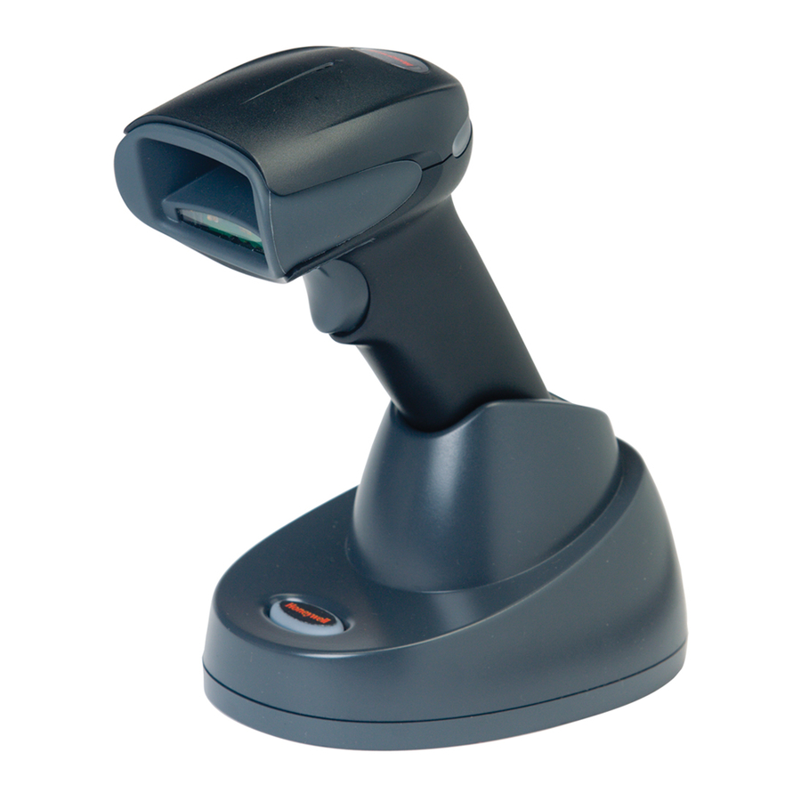
For patent information, please refer to www.honeywellaidc.com/patents. Solids and Water Protection The Xenon 1900 has a rating of IP41, immunity of foreign particles and dripping water. Warning To reduce the possibility of heat-related injuries, avoid touching sections of the scanner that feel warm. - Page 6 The Netherlands Honeywell shall not be liable for use of our product with equipment (i.e., power supplies, personal computers, etc.) that is not CE marked and does not comply with the Low Voltage Directive. This equipment is intended for use throughout the...
- Page 7 EN60950-1 Waste Electrical and Electronic Equipment Information Honeywell complies with Directive 2002/96/EC OF THE EUROPEAN PARLIAMENT AND OF THE COUNCIL on waste electrical and electronic equipment (WEEE). This product has required the extraction and use of natural resources for its production. It may contain hazardous sub- stances that could impact health and the environment, if not properly disposed.
- Page 8 Korea This product meets Korean agency approval. Mexico Conforms to NOM-019. This product meets Cofetel approval. Russia Gost-R certificate. Taiwan If the following label is attached to your product, the product meets Taiwan agency approval: BSMI Standard: CNS13438, CNS14336 (Xenon 1902 only) 依據標準...
- Page 9 Use only shielded data cables with this system. This unit has been tested with cables less than 3 meters. Cables greater than 3 meters may not meet class B performance. Caution: Any changes or modifications made to this equipment not expressly approved by Honeywell may void the FCC authorization to operate this equipment.
- Page 10 5627 BT Eindhoven The Netherlands Honeywell International Inc. shall not be liable for use of our product with equipment (i.e., power supplies, personal comput- ers, etc.) that is not CE marked and does not comply with the Low Voltage Directive.
- Page 11 International LED Safety Statement LEDs have been tested and classified as “EXEMPT RISK GROUP” to the standard: IEC 62471:2006. CB Scheme Certified to CB Scheme IEC 60950-1, Second Edition. Laser Safety Statement If the following label is attached to your product, it indicates the product contains a laser engine or laser aimer: LASER LIGHT.
- Page 12 The Netherlands Honeywell shall not be liable for use of our product with equipment (i.e., power supplies, personal computers, etc.) that is not CE marked and does not comply with the Low Voltage Directive. This equipment is intended for use throughout the...
- Page 13 EN60950-1 Waste Electrical and Electronic Equipment Information Honeywell complies with Directive 2002/96/EC OF THE EUROPEAN PARLIAMENT AND OF THE COUNCIL on waste electrical and electronic equipment (WEEE). This product has required the extraction and use of natural resources for its production. It may contain hazardous sub- stances that could impact health and the environment, if not properly disposed.
- Page 14 The Granit 1911i has a rating of IP65, immunity of foreign particles and dripping water. Patents For patent information, please refer to www.honeywellaidc.com/patents. Warning To reduce the possibility of heat-related injuries, avoid touching sections of the scanner that feel warm. Required Safety Labels Xenon 1900/1910/1902/1912 Scanner Illumination output Part Compliance Number, Serial Label...
- Page 15 CCB01-010BT Base Part Number, Serial Number and Compliance Revision Label Information locations location...
- Page 16 Granit 1910i/1911i Scanner Illumination output Laser Label location Part Number, Serial Compliance Number and Revision label location Information location...
- Page 17 CCB02-100BT Base Compliance Label locations...
-
Page 19: Table Of Contents
® Verifone Ruby Terminal Default Settings................2-5 ® Gilbarco Terminal Default Settings ..................2-5 Honeywell Bioptic Aux Port Configuration ................2-5 ® Datalogic™ Magellan Aux Port Configuration..............2-6 NCR Bioptic Aux Port Configuration ..................2-6 Wincor Nixdorf Terminal Default Settings ................2-6 Wincor Nixdorf Beetle™ Terminal Default Settings .............2-6 Keyboard Country Layout ....................2-7... - Page 20 RS232 Modifiers ........................ 2-17 RS232 Baud Rate......................2-17 RS232 Word Length: Data Bits, Stop Bits, and Parity ..........2-18 RS232 Receiver Time-Out................... 2-20 RS232 Handshaking....................2-20 RS232 Timeout......................2-21 XON/XOFF ........................2-21 ACK/NAK ........................2-21 Scanner to Bioptic Communication ................... 2-21 Scanner-Bioptic Packet Mode ..................
- Page 21 Scanner Modes ........................3-9 Charge Only Mode......................3-9 Linked Modes ........................ 3-9 Unlinking the Scanner ....................... 3-10 Override Locked Scanner .................... 3-10 Out-of-Range Alarm ......................3-10 Alarm Sound Type ....................... 3-11 Scanner Power Time-Out Timer..................3-11 Flexible Power Management ..................... 3-12 Batch Mode ........................
- Page 22 Good Read and Error Indicators..................4-2 Beeper – Good Read..................... 4-2 Beeper Volume – Good Read..................4-2 Beeper Pitch – Good Read.................... 4-3 Vibrate – Good Read ..................... 4-3 Beeper Pitch – Error ...................... 4-4 Beeper Duration – Good Read ..................4-4 LED –...
- Page 23 Output Sequence Overview....................4-19 Output Sequence Editor ....................4-19 To Add an Output Sequence ..................4-19 Other Programming Selections..................4-20 Output Sequence Editor ....................4-21 Partial Sequence ......................4-21 Require Output Sequence ................... 4-21 Multiple Symbols ....................... 4-22 No Read ..........................4-22 Video Reverse ........................
- Page 24 Code 39 ..........................7-4 Code 32 Pharmaceutical (PARAF) ................7-5 Full ASCII........................7-6 Code 39 Code Page ...................... 7-6 Interleaved 2 of 5......................... 7-7 NEC 2 of 5 ........................... 7-8 Code 93 ..........................7-9 Code 93 Code Page ....................7-10 Straight 2 of 5 Industrial (three-bar start/stop)..............
- Page 25 Chinese Sensible (Han Xin) Code..................7-43 Postal Codes - 2D ......................7-44 Single 2D Postal Codes:....................7-44 Combination 2D Postal Codes:..................7-45 Postal Codes - Linear ......................7-48 China Post (Hong Kong 2 of 5)..................7-48 Korea Post ........................7-49 Chapter 8 - Imaging Commands Single-Use Basis .........................
- Page 26 Chapter 12 - Product Specifications Xenon 1900/1910 Corded Scanner Product Specifications ..........12-1 Xenon 1902/1912 Cordless Scanner Product Specifications ..........12-1 Granit 1910i Industrial Corded Scanner Product Specifications........12-2 Granit 1911i Industrial Cordless Scanner Product Specifications ........12-3 CCB01-010BT Charge Base Product Specifications............12-4 CCB02-100BT Industrial Charge Base Product Specifications .........
- Page 27 Appendix A - Reference Charts Symbology Charts .......................A-1 Linear Symbologies .......................A-1 2D Symbologies......................A-3 Postal Symbologies .......................A-3 ASCII Conversion Chart (Code Page 1252)................A-3 Lower ASCII Reference Table.....................A-4 ISO 2022/ISO 646 Character Replacements ..............A-8 Unicode Key Maps ......................A-10...
-
Page 29: Chapter 1 - Getting Started
Product specifications, dimensions, warranty, and customer support information are also included. Honeywell bar code scanners are factory programmed for the most common terminal and communications settings. If you need to change these settings, programming is accomplished by scanning the bar codes in this guide. - Page 30 Corded Granit Scanner USB Connection: 2. If you are connecting a Granit scanner, make sure the cable is pushed tightly into the scanner. Loosen the locking plate and slide it over the base of the cable connector to lock the cable in place. Tighten the screw. CCB01-010BT Base USB Connection: CCB02-100BT Base...
-
Page 31: Connecting With Keyboard Wedge
3. If you are connecting a CCB01-010BT Base, make sure the cables are secured in the wireways in the bottom of the cordless base and the base sits flat on a horizontal surface. If you are connecting a CCB02-100BT Base, see Mounting a CCB02-100BT Base on page 1-8. - Page 32 CCB01-010BT Base Keyboard Wedge Connection: CCB02-100BT Base Keyboard Wedge Connection: Note: The power supply must be ordered separately, if needed. 4. If you are connecting a CCB01-010BT Base, make sure the cables are secured in the wireways in the bottom of the cordless base and the base sits flat on a horizontal surface.
-
Page 33: Connecting With Rs232 Serial Port
Connecting with RS232 Serial Port 1. Turn off power to the terminal/computer. 2. Connect the appropriate interface cable to the scanner. Note: For the scanner or cordless base to work properly, you must have the correct cable for your type of terminal/computer. Corded Xenon Scanner RS232 Serial Port Connection:... - Page 34 3. If you are connecting a Granit scanner, make sure the cable is pushed tightly into the scanner. Loosen the locking plate and slide it over the base of the cable connector to lock the cable in place. Tighten the screw. CCB01-010BT Base RS232 Serial Port Connection: CCB02-100BT Base...
-
Page 35: Connecting With Rs485
Connecting with RS485 A Xenon scanner or cordless base can be connected for an IBM POS terminal interface. (This interface is not available in the Granit devices.) 1. Connect the appropriate interface cable to the device, then to the computer. Corded Xenon Scanner RS485 Connection: CCB01-010BT Base... -
Page 36: Mounting A Ccb01-010Bt Charge Base
Mounting a CCB01-010BT Charge Base 2.36 in. 2.8 in. 59.84mm 72.1mm 3.35 in. 8x32 thread 85.09mm x .39 in. (10mm) deep Mounting a CCB02-100BT Base The CCB02-100BT Base can be mounted on either a horizontal or vertical surface. The cables can be routed through either the top or the bottom of the base. - Page 37 When mounted on a vertical surface, a locking system is used to secure the scanner when it is in the stand. When mounted on a horizontal surface, the locking mechanism should be set to unlocked (pushed up). When mounted on a vertical surface, the locking mechanism should be set to locked (pushed down).
-
Page 38: Reading Techniques
Reading Techniques The Xenon 1900/1902 scanners have a view finder that projects a bright red aiming beam that corresponds to the scanner’s horizontal field of view. The Xenon 1910/1912 and Granit 1910i/1911i scanners have an aiming pattern . The aiming beam or pattern should be centered over the bar code, but it can be positioned in any direction for a good read. -
Page 39: Setting Custom Defaults
Setting Custom Defaults You have the ability to create a set of menu commands as your own, custom defaults. To do so, scan the Set Custom Defaults bar code below before scanning the menu commands for your custom defaults. If a menu command requires scanning numeric codes from the back cover, then a Save code, that entire sequence will be saved to your custom defaults. - Page 40 1 - 12...
-
Page 41: Chapter 2 - Programming The Interface
Programming the Interface Introduction This chapter describes how to program your system for the desired interface. Programming the Interface - Plug and Play Plug and Play bar codes provide instant scanner set up for commonly used interfaces. Note: After you scan one of the codes, power cycle the host terminal to have the interface in effect. Keyboard Wedge If you want your system programmed for an IBM PC AT and compatibles keyboard wedge interface with a USA keyboard, scan the bar code below. -
Page 42: Rs485
RS485 Scan one of the following “Plug and Play” codes to program the scanner for an IBM POS terminal interface. Note: This interface is not supported in Granit devices. After scanning one of these codes, you must power cycle the cash register. IBM Port 5B Interface IBM Port 9B HHBCR-1 Interface... -
Page 43: Usb Ibm Surepos
RS485 Packet Length If you are using Packet mode, you can specify the size of the data “packet” that is sent to the host. Scan the Packet Length bar code, then then the packet size (from 20 - 256) from the Programming Chart inside the back cover of this manual, then Save. -
Page 44: Usb Hid
Scan the following code to program the scanner to emulate a regular RS232-based COM Port. If you are using a Microsoft® Windows® PC, you will need to download a driver from the Honeywell website (www.honeywellaidc.com). The driver will use the next available COM Port number. Apple® Macintosh computers recognize the scanner as a USB CDC class device and automatically use a class driver. -
Page 45: Verifone ® Ruby Terminal Default Settings
Honeywell Bioptic Aux Port Configuration Scan the following Plug and Play code to program the scanner for a Honeywell bioptic scanner auxiliary port configuration. This bar code sets the baud rate to 38400 bps and the data format to 8 data bits, no parity, 1 stop bit. -
Page 46: Datalogic™ Magellan ® Aux Port Configuration
® Datalogic™ Magellan Aux Port Configuration Scan the following Plug and Play code to program the scanner for a Datalogic Magellan auxiliary port configuration. This bar code sets the baud rate to 9600 bps and the data format to 8 data bits, no parity, 1 stop bit. Datalogic Magellan Settings NCR Bioptic Aux Port Configuration Scan the following Plug and Play code to program the scanner for an NCR bioptic scanner auxiliary port configuration. -
Page 47: Keyboard Country Layout
Keyboard Country Layout Scan the appropriate country code below to program the keyboard layout for your country or language. As a general rule, the following characters are supported, but need special care for countries other than the United States: @ | $ # { } [ ] = / ‘ \ < > ~ Keyboard Countries * United States Albania... - Page 48 Keyboard Countries (Continued) Bulgaria (Latin) Canada (French legacy) Canada (French) Canada (Multilingual) Croatia Czech Czech (Programmers) Czech (QWERTY) Czech (QWERTZ) Denmark Dutch (Netherlands) 2 - 8...
- Page 49 Keyboard Countries (Continued) Estonia Faroese Finland France Gaelic Germany Greek Greek (220 Latin) Greek (220) Greek (319 Latin) Greek (319) 2 - 9...
- Page 50 Keyboard Countries (Continued) Greek (Latin) Greek (MS) Greek (Polytonic) Hebrew Hungarian (101 key) Hungary Iceland Irish Italian (142) Italy Japan ASCII 2 - 10...
- Page 51 Keyboard Countries (Continued) Kazakh Kyrgyz (Cyrillic) Latin America Latvia Latvia (QWERTY) Lithuania Lithuania (IBM) Macedonia Malta Mongolian (Cyrillic) Norway 2 - 11...
- Page 52 Keyboard Countries (Continued) Poland Polish (214) Polish (Programmers) Portugal Romania Russia Russian (MS) Russian (Typewriter) Serbia (Cyrillic) Serbia (Latin) 2 - 12...
- Page 53 Keyboard Countries (Continued) Slovakia Slovakia (QWERTY) Slovakia (QWERTZ) Slovenia Spain Spanish variation Sweden Switzerland (French) Switzerland (German) Tatar Turkey F 2 - 13...
-
Page 54: Keyboard Style
Keyboard Countries (Continued) Turkey Q Ukrainian United Kingdom United States (Dvorak) United States (Dvorak left) United Stated (Dvorak right) United States (International) Uzbek (Cyrillic) Keyboard Style This programs keyboard styles, such as Caps Lock and Shift Lock. If you have used Keyboard Conversion settings, they will override any of the following Keyboard Style settings. -
Page 55: Keyboard Conversion
Shift Lock is used when you normally have the Shift Lock key on (not common to U.S. keyboards). Shift Lock Automatic Caps Lock is used if you change the Caps Lock key on and off. The software tracks and reflects if you have Caps Lock on or off . -
Page 56: Control Character Output
Control Character Output This selection sends a text string instead of a control character. For example, when the control character for a carriage return is expected, the output would display [CR] instead of the ASCII code of 0D. Refer to ASCII Conversion Chart (Code Page 1252) on page A-3. -
Page 57: Rs232 Modifiers
Turbo Mode: The scanner sends characters to a terminal faster. If the terminal drops characters, do not use Turbo Mode. Default = Off. Turbo Mode On * Turbo Mode Off Numeric Keypad Mode: Sends numeric characters as if entered from a numeric keypad. Default = Off. Numeric Keypad Mode On * Numeric Keypad Mode Off Automatic Direct Connect Mode: This selection can be used if you have an IBM AT style terminal and the system is dropping... -
Page 58: Rs232 Word Length: Data Bits, Stop Bits, And Parity
1200 2400 4800 9600 19200 38400 57,600 * 115,200 RS232 Word Length: Data Bits, Stop Bits, and Parity Data Bits sets the word length at 7 or 8 bits of data per character. If an application requires only ASCII Hex characters 0 through 7F decimal (text, digits, and punctuation), select 7 data bits. - Page 59 7 Data, 1 Stop, Parity None 7 Data, 1 Stop, Parity Odd 7 Data, 2 Stop, Parity Even 7 Data, 2 Stop Parity None 7 Data, 2 Stop, Parity Odd 8 Data, 1 Stop, Parity Even * 8 Data, 1 Stop, Parity None 8 Data, 1 Stop, Parity Odd 7 Data, 1 Stop, Parity Space 7 Data, 2 Stop, Parity Space...
-
Page 60: Rs232 Receiver Time-Out
7 Data, 2 Stop, Parity Mark 8 Data, 1 Stop, Parity Mark RS232 Receiver Time-Out The unit stays awake to receive data until the RS232 Receiver Time-Out expires. A manual or serial trigger resets the time- out. When an RS232 receiver is sleeping, a character may be sent to wake up the receiver and reset the time-out. A trans- action on the CTS line will also wake up the receiver. -
Page 61: Rs232 Timeout
Scanner to Bioptic Communication The following settings are used to set up communication between Honeywell scanners and bioptic scanners. Note: The scanner’s baud rate must be set to 38400 and the RS232 timeout must be set to 3000 in order to communicate with a bioptic scanner. -
Page 62: Scanner-Bioptic Packet Mode
Scanner-Bioptic Packet Mode Packet Mode On must be scanned to set the scanner’s format so it is compatible with a bioptic scanner. Default = Packet Mode Off. * Packet Mode Off Packet Mode On Scanner-Bioptic ACK/NAK Mode Bioptic ACK/Nak On must be scanned so the scanner will wait for an ACK or NAK from a bioptic scanner after each packet is sent. -
Page 63: Chapter 3 - Cordless System Operation
Cordless System Operation Note: This chapter applies only to cordless scanning systems. It does not apply to corded scanners. How the Cordless Charge Base/Access Point Works A cordless charge base or an Access Point provide the link between the cordless scanner and the host system. The base/ Access Point contains an interface assembly and an RF communication module. -
Page 64: Replacing A Linked Scanner
Scan the linking bar code on the top of the Access Point to establish a connection between the Access Point and the scanner. The scanner emits a short beep and flashes the green LED to confirm a connection with the Access Point. The Access Point’s Page button remains blue. Replacing a Linked Scanner If you need to replace a broken or lost scanner that is linked to a base or an Access Point, scan the Override Locked Scanner bar code below with a new scanner and place that scanner in the base, or scan the Access Point linking bar code. -
Page 65: Programming The Scanner And Base Or Access Point
Programming the Scanner and Base or Access Point When using the scanner and charge base or Access Point together as a system, menu parameters and configuration settings are stored in the charge base or Access Point. Therefore, when programming any menu configuration settings, the scanner must be linked to the intended charge base or Access Point. -
Page 66: About The Battery
• Although your battery can be recharged many times, it will eventually be depleted. Replace it after the battery is unable to hold an adequate charge. • If you are not sure if the battery or charger is working properly, send it to Honeywell International Inc. or an authorized service center for inspection. Refer to Customer Support on page 14-1 for additional information. -
Page 67: Beeper And Led Sequences And Meaning
Beeper and LED Sequences and Meaning The scanner contains LEDs on the rear of the unit that indicate linking status, decoding state, and battery condition. The base has LEDs on the top of the unit that indicate its power up, communication, and battery charge condition. The red LED = error; green LED = success of any type. -
Page 68: Reset Scanner
Base Power Communication Indicator Off Reset Scanner Scanning this bar code reboots the scanner and causes it to relink with the base or Access Point. Reset Scanner Scanning While in Base Cradle Note: This feature only applies to the CCB01-010BT base. If you want to be able to scan bar codes while the scanner is in the base cradle, scan the Scanning in Cradle On bar code below. -
Page 69: Paging
Default = External or Interface Cable Power. Base Charge Off External or Interface Cable Power External Power Only Paging Paging Mode By default, the paging button on the base or Access Point pages the scanners associated with that base or Access Point. If you want the paging button on your base or Access Point to be disabled, scan the Paging Mode Off bar code, below. -
Page 70: Error Indicators
High (4200 Hz) Error Indicators Beeper Pitch - Base Error Note: This feature only applies to the CCB01-010BT base. The CCB01-010BT base can be configured to beep at a particular pitch when an error occurs, such as transmission prob- lems to a host system. The beeper pitch codes modify the pitch (frequency) of the error tone the base emits when there is an error. -
Page 71: Scanner Address
Scanner Address Scan the bar code below to determine the address of the scanner you are using. Scanner Address Base or Access Point Address Scan the bar code below to determine the address of the base or Access Point you are using. Base Address Scanner Modes Your scanner is capable of working in single scanner mode, multiple scanner mode, or with Bluetooth devices other than the... -
Page 72: Unlinking The Scanner
Locked Link Mode - Single Scanner If you link a scanner to a base or an Access Point using the Locked Link Mode, other scanners are blocked from being linked if they are inadvertently placed into the base, or if the Access Point linking bar code is scanned. If you do place a different scanner into a base, it will charge the scanner, but the scanner will not be linked. -
Page 73: Alarm Sound Type
Default = 0 sec (no alarm). Base Alarm Duration Note: The Access Point does not have a base alarm. Scanner Alarm Duration Note: If you are out of range when you scan a bar code, you will receive an error tone even if you do not have the alarm set. You receive the error tone since the data could not be communicated to the base or Access Point or the host. -
Page 74: Flexible Power Management
If there are no trigger pulls during the timer interval, the scanner goes into power down mode. Whenever the trigger is enabled, the timer is reset. If the scanner is placed in the charge base cradle and the battery is in the process of being charged, the scanner will not go into power down mode. -
Page 75: Batch Mode
Scan one of the bar codes below to set the scanner’s power output to Full Power (100%), Medium Power (35%), Medium Low Power (5%), or Low Power (1%). Default = Full Power. Note: Setting a Granit scanner to anything lower than Full Power changes it to Class II Bluetooth. * Full Power Medium Power Medium Low Power... -
Page 76: Batch Mode Beep
Inventory Batch Mode Persistent Batch Mode Batch Mode Beep When scanning in Inventory Batch Mode (page 3-14), the scanner beeps every time a bar code is scanned. If using a Granit scanner, it also vibrates. When Batch Mode Beep is On, you will also hear a click when each bar code is sent to the host. -
Page 77: Batch Mode Quantity
Batch Mode Quantity When in Batch Mode, you may wish to transmit the number of multiple bar codes scanned, rather than a single bar code multiple times. For example, if you scan three bar codes called XYZ with Batch Mode Quantity Off, when you transmit your data it will appear as XYZ three times. -
Page 78: Batch Mode Output Order
Batch Mode Output Order When batch data is transmitted, select whether you want that data sent as FIFO (first-in first-out), or LIFO (last-in first-out). Default = Batch Mode FIFO. * Batch Mode FIFO Batch Mode LIFO 3 - 16... -
Page 79: Total Records
Total Records If you wish to output the total number of bar codes scanned when in Batch Mode, scan Total Records. Total Records Delete Last Code If you want to delete the last bar code scanned when in Batch Mode, scan Delete Last Code. Delete Last Code Clear All Codes If you want to clear the scanner’s buffer of all data accumulated in Batch Mode, scan Clear All Codes. -
Page 80: Multiple Scanner Operation
Batch Mode Transmit Delay Medium (500 ms) Batch Mode Transmit Delay Long (1000 ms) Multiple Scanner Operation Note: Multiple Scanner Operation Mode allows you to link up to 7 scanners to one base or Access Point. You cannot join an 8th scanner until you unlink one of the 7 scanners or take a scanner out of range. -
Page 81: Application Work Groups
You could assign all the scanners in the retail area to one work group and those in the warehouse to another. Consequently, any desired changes to either the retail or warehouse area would apply to all scanners in that particular work group. Honeywell’s online configuration tool, EZConfig-Scanning (page 10-2), makes it easy for you to program your sys- tem for use with multiple scanners and multiple work groups. -
Page 82: Application Work Group Selection
Application Work Group Selection This programming selection allows you to assign a scanner to a work group by scanning the bar code below. You may then program the settings (e.g., beeper volume, prefix/suffix, data formatter) that your application requires. Default = Group 0. * Group 0 Group 1 Group 2... -
Page 83: Resetting The Custom Defaults: All Application Work Groups
Using the Scanner with Bluetooth Devices The scanner can be used either with the charge base, an Access Point, or with other Bluetooth devices. Those devices include personal computers, laptops, PDAs, and Honeywell mobility systems devices. Bluetooth HID Keyboard Connect Your scanner can be paired with Bluetooth-capable devices, such as iPads, smart phones, and laptops, so that scanned data appears on your device screen as though it was entered on the keyboard. -
Page 84: Bluetooth Hid Keyboard Disconnect
Save Bluetooth HID Keyboard Disconnect If your scanner has been connected directly to an iPad, smart phone, or laptop using Bluetooth HID Keyboard Connect (page 3-21), you must disconnect it in order to once again communicate with the base or Access Point. Scan the Blue- tooth HID Keyboard Disconnect bar code to unlink the scanner from the currently linked host. -
Page 85: Bluetooth Serial Port - Pcs/Laptops
PDAs/Mobility Systems Devices You may also use the scanner with a PDA or a Honeywell Mobility Systems device. Scan the bar code below and follow the instructions supplied with your Bluetooth device to locate the scanner, and connect with it. -
Page 86: Auto Reconnect Mode
Auto Reconnect Mode Auto Reconnect controls whether or not the scanner automatically begins the relink process when a loss of connection is detected. When the Auto Reconnect On bar code is scanned, the scanner begins the relink process immediately, without user intervention. -
Page 87: Relink Time-Out
Scan the Maximum Link Attempts bar code, then scan the number of attempts for the setting (from 0-100) from the inside back cover. Scan Save to save the setting. Default = 0. Maximum Link Attempts Note: When Auto Reconnect Mode is On, setting Maximum Link Attempts to zero will cause the scanner to try to link until the Power Time-Out Timer setting (see page 3-11) expires. -
Page 88: Host Acknowledgment
Host Acknowledgment Some applications require that the host terminal (or server) validate incoming bar code data (database look-up) and provide acknowledgement to the scanner whether or not to proceed. In Host ACK Mode, the scanner waits for this acknowledgement after each scan. Visual and audible acknowledgements provide valuable feedback to the scan operator. The Host ACK func- tionality is controlled via a number of pre-defined escape commands that are sent to the scanner to make it behave in different ways. - Page 89 Host ACK On/Off Host ACK On * Host ACK Off Host ACK Responses Command Action [ESC] a, Double beeps to indicate a successful menu change was made. [ESC] b, Razz or error tone to indicate a menu change was unsuccessful. [ESC] 1, The green LED illuminates for 135 milliseconds followed by a pause.
- Page 90 3 - 28...
-
Page 91: Chapter 4 - Input/Output Settings
Input/Output Settings Power Up Beeper Note: This feature does not apply to the CCB02-100BT base. The scanner can be programmed to beep when it’s powered up. If you are using a cordless system, the base can also be pro- grammed to beep when it is powered up. Scan the Off bar code(s) if you don’t want a power up beep. Default = Power Up Beeper On - Scanner. -
Page 92: Trigger Click
Trigger Click To hear an audible click every time the scanner trigger is pressed, scan the Trigger Click On bar code below. Scan the Trigger Click Off code if you don’t wish to hear the click. (This feature has no effect on serial or automatic triggering.) Default = Trigger Click Off. -
Page 93: Beeper Pitch - Good Read
Beeper Pitch – Good Read The beeper pitch codes modify the pitch (frequency) of the beep the scanner emits on a good read. The Medium pitch dif- fers for the Xenon and Granit scanners. Default = Medium. Low (1600 Hz) * Medium - Xenon (2700 Hz) * Medium - Granit... -
Page 94: Beeper Pitch - Error
Beeper Pitch – Error The beeper pitch codes modify the pitch (frequency) of the sound the scanner emits when there is a bad read or error. Default = Razz. * Razz (250 Hz) Medium (3250 Hz) High (4200 Hz) Beeper Duration – Good Read The beeper duration codes modify the length of the beep the scanner emits on a good read. -
Page 95: Number Of Beeps - Error
Programming Chart inside the back cover of this manual. Default = 1. Number of Good Read Beeps/LED Flashes Number of Beeps – Error The number of beeps and LED flashes emitted by the scanner for a bad read or error can be programmed from 1 - 9. For example, if you program this option to have five error beeps, there will be five error beeps and five LED flashes in response to an error. -
Page 96: User-Specified Good Read Delay
User-Specified Good Read Delay If you want to set your own length for the good read delay, scan the bar code below, then set the delay (from 0 - 30,000 mil- liseconds) by scanning digits from the inside back cover, then scanning Save. User-Specified Good Read Delay Manual Trigger Modes When in manual trigger mode, the scanner scans until a bar code is read, or until the trigger is released. -
Page 97: Serial Trigger Mode
Serial Trigger Mode You can activate the scanner either by pressing the trigger, or using a serial trigger command (see Trigger Commands on page 11-3). When in serial mode, the scanner scans until a bar code has been read or until the deactivate command is sent. The scanner can also be set to turn itself off after a specified time has elapsed (see Read Time-Out, which follows). -
Page 98: Presentation Led Behavior After Decode
Presentation LED Behavior after Decode When a scanner is in presentation mode, the LEDs dim 30 seconds after a bar code is decoded. If you wish to dim the LEDs immediately after a bar code is decoded, scan the LEDs Off bar code, below. Default = LEDs On. * LEDs On LEDs Off Presentation Sensitivity... - Page 99 In the example below, the white box is the centering window. The centering window has been set to 20% left, 30% right, 8% top, and 25% bottom. Since Bar Code 1 passes through the centering window, it will be read. Bar Code 2 does not pass through the centering window, so it will not be read.
-
Page 100: In-Stand Sensor Mode
Left of Presentation Centering Window Right of Presentation Centering Window In-Stand Sensor Mode Note: The In-Stand Sensor feature only applies to Xenon products. This feature senses when the scanner is removed from the stand and tells it to begin manual triggering. When Sensor On is enabled, the scanner defaults to Streaming Presentation Mode when it is in the stand, and to Manual Trigger Mode when it is removed from the stand. -
Page 101: Streaming Presentation™ Mode
Streaming Presentation ™ Mode When in Streaming Presentation mode, the scanner’s aimer goes out after a short time, but the scan illumination remains on all the time to continuously search for bar codes. Two modes are available, Normal and Enhanced. Normal mode offers good scan speed and the longest working ranges (depth of field). -
Page 102: 2D Reread Delay
Scan the Hands Free Time-Out bar code, then scan the time-out duration (from 0-300,000 milliseconds) from the inside back cover, and Save. Default = 5,000 ms. Hands Free Time-Out Reread Delay This sets the time period before the scanner can read the same bar code a second time. Setting a reread delay protects against accidental rereads of the same bar code. -
Page 103: Character Activation Mode
Short (1000ms) Medium (2000ms) Long (3000ms) Extra Long (4000ms) Character Activation Mode You may use a character sent from the host to trigger the scanner to begin scanning. When the activation character is received, the scanner continues scanning until either the Character Activation Timeout (page 4-14), the deactivation character is received (see... -
Page 104: End Character Activation After Good Read
End Character Activation After Good Read After a bar code is successfully detected and read from the scanner, the illumination can be programmed either to remain on and scanning, or to turn off. When End Character Activation After Good Read is enabled, the illumination turns off and stops scanning after a good read. -
Page 105: Deactivation Character
Deactivation Character This sets the character used to terminate scanning when using Character Deactivation Mode. On the ASCII Conversion Chart (Code Page 1252), page A-3, find the hex value that represents the character you want to use to terminate scanning. Scan the following bar code, then use the Programming Chart inside the back cover of this manual to read the alphanu-... -
Page 106: User-Specified Aimer Delay
User-Specified Aimer Delay If you want to set your own length for the duration of the delay, scan the bar code below, then set the time-out by scanning digits (0 - 4,000 ms) from the Programming Chart inside the back cover of this manual, then scan Save. Delay Duration Aimer Mode This feature allows you to turn the aimer on and off. - Page 107 In the example below, the white box is the centering window. The centering window has been set to 20% left, 30% right, 8% top, and 25% bottom. Since Bar Code 1 passes through the centering window, it will be read. Bar Code 2 does not pass through the centering window, so it will not be read.
-
Page 108: Preferred Symbology
Right of Centering Window Preferred Symbology The scanner can be programmed to specify one symbology as a higher priority over other symbologies in situations where both bar code symbologies appear on the same label, but the lower priority symbology cannot be disabled. For example, you may be using the scanner in a retail setting to read U.P.C. -
Page 109: Preferred Symbology Time-Out
If you want to set additional low priority symbologies, scan FF, then scan the 2 digit hex value from the Programming Chart for the next symbology. You can program up to 5 low priority symbologies. Scan Save to save your selection. Default = None . -
Page 110: Other Programming Selections
5. End Output Sequence Editor Scan F F to enter an Output Sequence for an additional symbology, or Save to save your entries. Other Programming Selections • Discard This exits without saving any Output Sequence changes. Output Sequence Example In this example, you are scanning Code 93, Code 128, and Code 39 bar codes, but you want the scanner to output Code 39 1st, Code 128 2nd, and Code 93 3rd, as shown below. -
Page 111: Output Sequence Editor
start character match for Code 39, 41h = “A” termination string for first code code identifier for Code 128 0013 B - Code 128 sample length (12) plus CR suffix (1) = 13 start character match for Code 128, 42h = “B” termination string for second code code identifier for Code 93 0012... -
Page 112: Multiple Symbols
When the output sequence is Off , the bar code data is output to the host as the scanner decodes it. Default = Off. Note: This selection is unavailable when the Multiple Symbols Selection is turned on. Required On/Not Required *Off Multiple Symbols When this programming selection is turned On, it allows you to read multiple symbols with a single pull of the scanner’s trigger. -
Page 113: Video Reverse
Video Reverse Video Reverse is used to allow the scanner to read bar codes that are inverted. The Video Reverse Off bar code below is an example of this type of bar code. Scan Video Reverse Only to read only inverted bar codes. Scan Video Reverse and Stan- dard Bar Codes to read both types of codes. - Page 114 Vertical, Bottom to Top Upside Down Vertical, Top to Bottom 4 - 24...
-
Page 115: Chapter 5 - Data Editing
Data Editing Prefix/Suffix Overview When a bar code is scanned, additional information is sent to the host computer along with the bar code data. This group of bar code data and additional, user-defined data is called a “message string.” The selections in this section are used to build the user-defined data into the message string. -
Page 116: To Clear One Or All Prefixes Or Suffixes
Example: Add a Suffix to a specific symbology To send a CR (carriage return)Suffix for U.P.C. only: Step 1. Scan Add Suffix. Step 2. Determine the 2 digit hex value from the Symbology Chart (included in the Symbology Charts, beginning on page A-1) for U.P.C.. -
Page 117: Suffix Selections
Suffix Selections Add Suffix Clear One Suffix Clear All Suffixes Function Code Transmit When this selection is enabled and function codes are contained within the scanned data, the scanner transmits the function code to the terminal. Charts of these function codes are provided in Supported Interface Keys starting on page... -
Page 118: User Specified Intercharacter Delay
To remove this delay, scan the Intercharacter Delay bar code, then set the number of delays to 0. Scan the Save bar code using the Programming Chart inside the back cover of this manual. Note: Intercharacter delays are not supported in USB serial emulation. User Specified Intercharacter Delay An intercharacter delay of up to 5000 milliseconds (in 5ms increments) may be placed after the transmission of a particular character of scanned data. -
Page 119: Intermessage Delay
Intermessage Delay An intermessage delay of up to 5000 milliseconds (in 5ms increments) may be placed between each scan transmission. Scan the Intermessage Delay bar code below, then scan the number of 5ms delays, and the Save bar code using the Programming Chart inside the back cover of this manual. - Page 120 5 - 6...
-
Page 121: Chapter 6 - Data Formatting
Data Formatting Data Format Editor Introduction You may use the Data Format Editor to change the scanner’s output. For example, you can use the Data Format Editor to insert characters at certain points in bar code data as it is scanned. The selections in the following pages are used only if you wish to alter the output. -
Page 122: Other Programming Selections
Step 5. Length Specify what length (up to 9999 characters) of data will be acceptable for this symbology. Scan the four digit data length from the Programming Chart inside the back cover of this manual. For example, 50 characters is entered as 0050. Note: 9999 indicates all lengths. -
Page 123: Terminal Id Table
Terminal ID Table Terminal Model(s) Terminal ID PC keyboard (HID) Mac Keyboard PC Keyboard (Japanese) Serial (COM driver required) HID POS USB SurePOS Handheld USB SurePOS Tabletop Serial RS232 TTL RS232 True RS485 (IBM-HHBCR 1+2, 46xx) Keyboard PS2 compatibles AT compatibles Data Format Editor Commands When working with the Data Format Editor, a virtual cursor is moved along your input data string. -
Page 124
F1 is the “Send all characters” command 0D is the hex value for a CR The data is output as: 1234567890 ABCDEFGHIJ
Send all characters up to a particular character F3 Include in the output message all characters from the input message, starting with the character at the current cursor position and continuing to, but not including, the search character “ss,”... -
Page 125
Insert symbology name B3 Insert the name of the bar code’s symbology in the output message, without moving the cursor. Only symbologies with a Honeywell ID are included (see Symbology Charts on page A-1). Refer to the ASCII Conversion Chart (Code Page 1252), beginning on page A-3 for decimal, hex and character codes. -
Page 126: Move Commands
Insert bar code length B4 Insert the bar code’s length in the output message, without moving the cursor. The length is expressed as a numeric string and does not include leading zeroes. B3 and B4 Example: Insert the symbology name and length Send the symbology name and length before the bar code data from the bar code above. -
Page 127: Search Commands
F5 Example: Move the cursor forward and send the data Move the cursor forward 3 characters, then send the rest of the bar code data from the bar code above. End with a carriage return. Command string: F503F10D F5 is the “Move the cursor forward a number of characters” command 03 is the number of characters to move the cursor F1 is the “Send all characters”... - Page 128 F8 Example: Send bar code data that starts after a particular character Search for the letter “D” in bar codes and send all the data that follows, including the “D.” Using the bar code above: Command string: F844F10D F8 is the “Search forward for a character” command 44 is the hex value for “D”...
-
Page 129: Miscellaneous Commands
Search forward for a non-matching character E6 Search the input message forward for the first non-“xx” character from the current cursor position, leaving the cursor pointing to the non-“xx” character. Syntax = E6xx where xx stands for the search character’s hex value for its ASCII code. - Page 130 Stop suppressing characters FC Disables suppress filter and clear all suppressed characters. Syntax = FC. Replace characters E4 Replaces up to 15 characters in the output message, without moving the cursor. Replacement continues until the E5 command is encountered. Syntax = E4nnxx ...zz where nn is the total count of the number of characters in the list (characters to be replaced plus replacement characters);...
-
Page 131
If this bar code is read, the next data format, if there is one, will be used on the data. If there is no other format, the format fails and the raw data is output as AB1234. If this bar code is read: the data is output as: 1234AB
... -
Page 132: Data Formatter
Data Formatter When Data Formatter is turned Off, the bar code data is output to the host as read, including prefixes and suffixes. Data Formatter Off You may wish to require the data to conform to a data format you have created and saved. The following settings can be applied to your data format: Data Formatter On, Not Required, Keep Prefix/Suffix Scanned data is modified according to your data format, and prefixes and suffixes are transmitted. -
Page 133: Data Format Non-Match Error Tone
Data Format Non-Match Error Tone When a bar code is encountered that doesn’t match your required data format, the scanner normally generates an error tone. However, you may want to continue scanning bar codes without hearing the error tone. If you scan the Data Format Non-Match Error Tone Off bar code, data that doesn’t conform to your data format is not transmitted, and no error tone will sound. - Page 134 For example, you may have set your device to the data format you saved as Data Format 3. You can switch to Data Format 1 for a single trigger pull by scanning the Single Scan-Data Format 1 bar code below. The next bar code that is scanned uses Data Format 1, then reverts back to Data Format 3.
-
Page 135: All Symbologies
Symbologies This programming section contains the following menu selections. Refer to Chapter 11 for settings and defaults. • All Symbologies • Interleaved 2 of 5 • Aztec Code • Korea Post • China Post (Hong Kong 2 of 5) • Matrix 2 of 5 •... -
Page 136: Codabar
EXAMPLE: Decode only those bar codes with a count of 15 characters. Min. length = 15Max. length = 15 For a value other than the minimum and maximum message length defaults, scan the bar codes included in the explanation of the symbology, then scan the digit value of the message length and Save bar codes on the Programming Chart inside the back... -
Page 137: Codabar Concatenation
Validate Modulo 16, but Don’t Transmit Validate Modulo 16 and Transmit Codabar Concatenation Codabar supports symbol concatenation. When you enable concatenation, the scanner looks for a Codabar symbol having a “D” start character, adjacent to a symbol having a “D” stop character. In this case the two messages are concatenated into one with the “D”... -
Page 138: Code 39
Code 39 < Default All Code 39 Settings > Code 39 On/Off * On Code 39 Start/Stop Characters Start/Stop characters identify the leading and trailing ends of the bar code. You may either transmit, or not transmit Start/ Stop characters. Default = Don’t Transmit. Transmit * Don’t Transmit Code 39 Check Character... -
Page 139: Code 39 Message Length
Code 39 Message Length Scan the bar codes below to change the message length. Refer to Message Length Description (page 7-1) for additional information. Minimum and Maximum lengths = 0-48. Minimum Default = 0, Maximum Default = 48. Minimum Message Length Maximum Message Length Code 39 Append This function allows the scanner to append the data from several Code 39 bar codes together before transmitting them to... -
Page 140: Full Ascii
Full ASCII If Full ASCII Code 39 decoding is enabled, certain character pairs within the bar code symbol will be interpreted as a single character. For example: $V will be decoded as the ASCII character SYN, and /C will be decoded as the ASCII character #. Default = Off . -
Page 141: Interleaved 2 Of 5
Interleaved 2 of 5 < Default All Interleaved 2 of 5 Settings > Interleaved 2 of 5 On/Off * On Check Digit No Check Digit indicates that the scanner reads and transmits bar code data with or without a check digit. When Check Digit is set to Validate, but Don’t Transmit, the unit only reads Interleaved 2 of 5 bar codes printed with a check digit, but will not transmit the check digit with the scanned data. -
Page 142: Nec 2 Of
Maximum Message Length NEC 2 of 5 < Default All NEC 2 of 5 Settings > NEC 2 of 5 On/Off * On Check Digit No Check Digit indicates that the scanner reads and transmits bar code data with or without a check digit. When Check Digit is set to Validate, but Don’t Transmit, the unit only reads NEC 2 of 5 bar codes printed with a check digit, but will not transmit the check digit with the scanned data. -
Page 143: Code 93
NEC 2 of 5 Message Length Scan the bar codes below to change the message length. Refer to Message Length Description (page 7-1) for additional information. Minimum and Maximum lengths = 2-80. Minimum Default = 4, Maximum Default = 80. Minimum Message Length Maximum Message Length Code 93... -
Page 144: Code 93 Code Page
Code 93 Append This function allows the scanner to append the data from several Code 93 bar codes together before transmitting them to the host computer. When this function is enabled, the scanner stores those Code 93 bar codes that start with a space (excluding the start and stop symbols), and does not immediately transmit the data. -
Page 145: Straight 2 Of 5 Industrial (Three-Bar Start/Stop)
Straight 2 of 5 Industrial (three-bar start/stop)Straight 2 of 5 Industrial On/Off * Off Straight 2 of 5 Industrial Message Length Scan the bar codes below to change the message length. Refer to Message Length Description (page 7-1) for additional information. -
Page 146: Straight 2 Of 5 Iata (Two-Bar Start/Stop)
Straight 2 of 5 IATA (two-bar start/stop)Straight 2 of 5 IATA On/Off * Off Straight 2 of 5 IATA Message Length Scan the bar codes below to change the message length. Refer to Message Length Description (page 7-1) for additional information. -
Page 147: Matrix 2 Of 5
Matrix 2 of 5Matrix 2 of 5 On/Off * Off Matrix 2 of 5 Message Length Scan the bar codes below to change the message length. Refer to Message Length Description (page 7-1) for additional information. -
Page 148: Check Digits Required
Code 11Code 11 On/Off * Off Check Digits Required This option sets whether 1 or 2 check digits are required with Code 11 bar codes. Default = Two Check Digits. One Check Digit * Two Check Digits Code 11 Message Length Scan the bar codes below to change the message length. -
Page 149: Code 11
Code 128Code 128 On/Off * On ISBT 128 Concatenation In 1994 the International Society of Blood Transfusion (ISBT) ratified a standard for communicating critical blood informa- tion in a uniform manner. The use of ISBT formats requires a paid license. The ISBT 128 Application Specification describes 1) the critical data elements for labeling blood products, 2) the current recommendation to use Code 128 due to its high degree of security and its space-efficient design, 3) a variation of Code 128 that supports concatenation of neigh- boring symbols, and 4) the standard layout for bar codes on a blood product label. -
Page 150: Code 128 Code Page
Code 128 Append This function allows the scanner to append the data from several Code 128 bar codes together before transmitting them to the host computer. When the scanner encounters a Code 128 bar code with the append trigger character(s), it buffers Code 128 bar codes until it reads a Code 128 bar code that does not have the append trigger. -
Page 151: Gs1-128
GS1-128GS1-128 On/Off * On GS1-128 Message Length Scan the bar codes below to change the message length. Refer to Message Length Description (page 7-1) for additional information. Minimum and Maximum lengths = 1-80. Minimum Default = 1, Maximum Default = 80. Minimum Message Length Maximum Message Length 7 - 17... -
Page 152: Telepen
TelepenTelepen On/Off * Off Telepen Output Using AIM Telepen Output, the scanner reads symbols with start/stop pattern 1 and decodes them as standard full ASCII (start/stop pattern 1). When Original Telepen Output is selected, the scanner reads symbols with start/stop pattern 1 and decodes them as compressed numeric with optional full ASCII (start/stop pattern 2). -
Page 153: Upc-A
UPC-AUPC-A On/Off * On Note: To convert UPC-A bar codes to EAN-13, see Convert UPC-A to EAN-13 on page 7-24. UPC-A Check Digit This selection allows you to specify whether the check digit should be transmitted at the end of the scanned data or not. Default = On . - Page 154 UPC-A Addenda This selection adds 2 or 5 digits to the end of all scanned UPC-A data. Default = Off for both 2 Digit and 5 Digit Addenda. 2 Digit Addenda On * 2 Digit Addenda Off 5 Digit Addenda On * 5 Digit Addenda Off UPC-A Addenda Required When Required is scanned, the scanner will only read UPC-A bar codes that have addenda.
-
Page 155: Upc-A/Ean-13
UPC-A/EAN-13 with Extended Coupon Code Use the following codes to enable or disable UPC-A and EAN-13 with Extended Coupon Code. When left on the default setting (Off), the scanner treats Coupon Codes and Extended Coupon Codes as single bar codes. If you scan the Allow Concatenation code, when the scanner sees the coupon code and the extended coupon code in a single scan, it transmits both as separate symbologies. -
Page 156: Upc-E0
UPC-E0UPC-E0 On/Off Most U.P.C. bar codes lead with the 0 number system. To read these codes, use the UPC-E0 On selection. If you need to (page 7-24). Default = On. read codes that lead with the 1 number system, use UPC-E1 * UPC-E0 On UPC-E0 Off... - Page 157 UPC-E0 Addenda Separator When this feature is On, there is a space between the data from the bar code and the data from the addenda. When turned Off, there is no space. Default = On. * On UPC-E0 Check Digit Check Digit specifies whether the check digit should be transmitted at the end of the scanned data or not.
-
Page 158: Upc-E1
5 Digit Addenda On * 5 Digit Addenda Off UPC-E1 Most U.P.C. bar codes lead with the 0 number system. For these codes, use UPC-E0 (page 7-22). If you need to read codes that lead with the 1 number system, use the UPC-E1 On selection. Default = Off. UPC-E1 On * UPC-E1 Off EAN/JAN-13... - Page 159 * Do not Convert UPC-A EAN/JAN-13 Check Digit This selection allows you to specify whether the check digit should be transmitted at the end of the scanned data or not. Default = On. * On EAN/JAN-13 Addenda This selection adds 2 or 5 digits to the end of all scanned EAN/JAN-13 data. Default = Off for both 2 Digit and 5 Digit Addenda.
-
Page 160: Isbn Translate
* Not Required EAN/JAN-13 Addenda Separator When this feature is On, there is a space between the data from the bar code and the data from the addenda. When turned Off, there is no space. Default = On. * On Note: If you want to enable or disable EAN13 with Extended Coupon Code, refer to UPC-A/EAN-13 with Extended Coupon Code... -
Page 161: Ean/Jan-8
EAN/JAN-8EAN/JAN-8 On/Off * On EAN/JAN-8 Check Digit This selection allows you to specify whether the check digit should be transmitted at the end of the scanned data or not. Default = On. * On EAN/JAN-8 Addenda This selection adds 2 or 5 digits to the end of all scanned EAN/JAN-8 data. - Page 162 * 5 Digit Addenda Off EAN/JAN-8 Addenda Required When Required is scanned, the scanner will only read EAN/JAN-8 bar codes that have addenda. Default = Not Required. Required * Not Required EAN/JAN-8 Addenda Separator When this feature is On, there is a space between the data from the bar code and the data from the addenda. When turned Off, there is no space.
-
Page 163: Msi
MSI On/Off * Off MSI Check Character Different types of check characters are used with MSI bar codes. You can program the scanner to read MSI bar codes with Type 10 check characters. Default = Validate Type 10, but Don’t Transmit. When Check Character is set to Validate Type 10/11 and Transmit, the scanner will only read MSI bar codes printed with the specified type check character(s), and will transmit the character(s) at the end of the scanned data. -
Page 164: Msi Message Length
Validate Type 10 then Type 11 Character and Transmit Disable MSI Check Characters MSI Message Length Scan the bar codes below to change the message length. Refer to Message Length Description (page 7-1) for additional information. Minimum and Maximum lengths = 4-48. Minimum Default = 4, Maximum Default = 48. Minimum Message Length Maximum Message Length 7 - 30... -
Page 165: Gs1 Databar Omnidirectional
GS1 DataBar Omnidirectional < Default All GS1 DataBar Omnidirectional Settings > GS1 DataBar Omnidirectional On/Off * On GS1 DataBar Limited < Default All GS1 DataBar Limited Settings > GS1 DataBar Limited On/Off * On 7 - 31... -
Page 166: Gs1 Databar Expanded
GS1 DataBar Expanded < Default All GS1 DataBar Expanded Settings > GS1 DataBar Expanded On/Off * On GS1 DataBar Expanded Message Length Scan the bar codes below to change the message length. Refer to Message Length Description (page 7-1) for additional information. -
Page 167: Codablock A
Codablock ACodablock A On/Off * Off Codablock A Message Length Scan the bar codes below to change the message length. Refer to Message Length Description (page 7-1) for additional information. Minimum and Maximum lengths = 1-600. Minimum Default = 1, Maximum Default = 600. Minimum Message Length Maximum Message Length 7 - 33... -
Page 168: Codablock F
Codablock FCodablock F On/Off * Off Codablock F Message Length Scan the bar codes below to change the message length. Refer to Message Length Description (page 7-1) for additional information. Minimum and Maximum lengths = 1-2048. Minimum Default = 1, Maximum Default = 2048. Minimum Message Length Maximum Message Length 7 - 34... -
Page 169: Pdf417
PDF417 < Default All PDF417 Settings > PDF417 On/Off * On PDF417 Message Length Scan the bar codes below to change the message length. Refer to Message Length Description (page 7-1) for additional information. Minimum and Maximum lengths = 1-2750. Minimum Default = 1, Maximum Default = 2750. Minimum Message Length Maximum Message Length MacroPDF417... -
Page 170: Micropdf417
MicroPDF417 < Default All MicroPDF417 Settings > MicroPDF417 On/Off * Off MicroPDF417 Message Length Scan the bar codes below to change the message length. Refer to Message Length Description (page 7-1) for additional information. Minimum and Maximum lengths = 1-366. Minimum Default = 1, Maximum Default = 366. Minimum Message Length Maximum Message Length GS1 Composite Codes... -
Page 171: Gs1 Composite Code Message Length
UPC/EAN Version Scan the UPC/EAN Version On bar code to decode GS1 Composite symbols that have a U.P.C. or an EAN linear compo- nent. (This does not affect GS1 Composite symbols with a GS1-128 or GS1 linear component.) Default = UPC/EAN Ver- sion Off. -
Page 172: Tcif Linked Code 39 (Tlc39)
GS1 DataBar Emulation GS1 Code Expansion Off EAN8 to EAN13 Conversion * GS1 Emulation Off TCIF Linked Code 39 (TLC39) This code is a composite code since it has a Code 39 linear component and a MicroPDF417 stacked code component. All bar code readers are capable of reading the Code 39 linear component. -
Page 173: Qr Code Message Length
QR Code Message Length Scan the bar codes below to change the message length. Refer to Message Length Description (page 7-1) for additional information. Minimum and Maximum lengths = 1-7089. Minimum Default = 1, Maximum Default = 7089. Minimum Message Length Maximum Message Length QR Code Append This function allows the scanner to append the data from several QR Code bar codes together before transmitting them to... -
Page 174: Data Matrix
Data Matrix < Default All Data Matrix Settings > Data Matrix On/Off * On Data Matrix Message Length Scan the bar codes below to change the message length. Refer to Message Length Description (page 7-1) for additional information. Minimum and Maximum lengths = 1-3116. Minimum Default = 1, Maximum Default = 3116. Minimum Message Length Maximum Message Length Data Matrix Append... -
Page 175: Maxicode
codes were created (see ISO 2022/ISO 646 Character Replacements on page A-8), and scan the value and the Save bar code from the Programming Chart on the inside the back cover of this manual. The data characters should then appear properly. -
Page 176: Aztec Code
Aztec Code < Default All Aztec Code Settings > Aztec Code On/Off * On Aztec Code Message Length Scan the bar codes below to change the message length. Refer to Message Length Description (page 7-1) for additional information. Minimum and Maximum lengths = 1-3832. Minimum Default = 1, Maximum Default = 3832. Minimum Message Length Maximum Message Length Aztec Append... -
Page 177: Chinese Sensible (Han Xin) Code
codes were created (see ISO 2022/ISO 646 Character Replacements on page A-8), and scan the value and the Save bar code from the Programming Chart on the inside the back cover of this manual. The data characters should then appear properly. -
Page 178: Postal Codes - 2D
Postal Codes - 2D The following lists the possible 2D postal codes, and 2D postal code combinations that are allowed. Only one 2D postal code selection can be active at a time. If you scan a second 2D postal code selection, the first selection is overwritten. Default = 2D Postal Codes Off. -
Page 179: Combination 2D Postal Codes
Postnet On Also see Postnet Check Digit, page 7-47. Postnet with B and B’ Fields On InfoMail On Combination 2D Postal Codes: InfoMail and British Post On Intelligent Mail Bar Code and Postnet with B and B’ Fields On Postnet and Postal-4i On Postnet and Intelligent Mail Bar Code On... - Page 180 Planet Code and Postnet with B and B’ Fields On Planet Code and Postal-4i On Planet Code and Intelligent Mail Bar Code On Planet Code, Postnet, and Postal-4i On Planet Code, Postnet, and Intelligent Mail Bar Code On Planet Code, Postal-4i, and Intelligent Mail Bar Code On Postnet,...
- Page 181 Planet Code, Postal-4i, Intelligent Mail Bar Code, and Postnet On Planet Code, Postal-4i, Intelligent Mail Bar Code, and Postnet with B and B’ Fields On Planet Code Check Digit This selection allows you to specify whether the check digit should be transmitted at the end of Planet Code data. Default = Don’t Transmit.
-
Page 182: Postal Codes - Linear
Combination C and N Tables causes the field to be interpreted using either the C or N Tables. * Bar Output Numeric N Table Alphanumeric C Table Combination C and N Tables Postal Codes - Linear The following lists linear postal codes. Any combination of linear postal code selections can be active at a time. China Post (Hong Kong 2 of 5)... -
Page 183: Korea Post
Maximum Message Length Korea PostKorea Post * Off Korea Post Message Length Scan the bar codes below to change the message length. Refer to Message Length Description (page 7-1) for addi- tional information. Minimum and Maximum lengths = 2-80. Minimum Default = 4, Maximum Default = 48. Minimum Message Length Maximum Message Length Korea Post Check Digit... - Page 184 7 - 50...
-
Page 185: Chapter 8 - Imaging Commands
Imaging Commands The scanner is like a digital camera in the way it captures, manipulates, and transfers images. The following commands allow you to alter the way the scanner performs these functions. Note: If you are using the scanner in a stand, you must set the In-Stand Sensor Mode to Off in order to take images (see Stand Sensor Mode on page 4-10). - Page 186 0B No beep (default) 1B Sounds a beep when the image is captured. T - Wait for Trigger Waits for a hardware button push before taking the image. This is only available when using Photo Style (1P). 0T Takes image immediately (default) 1T Waits for a button push, then takes the image L - LED State Determines if the LEDs should be on or off, and when.
-
Page 187: Image Ship - Imgshp
W - Target White Value Sets the target for the median grayscale value in the captured image. For capturing close-up images of high contrast doc- uments, a lower setting, such as 75, is recommended. Higher settings result in longer exposure times and brighter images, but if the setting is too high, the image may be overexposed. - Page 188 Enhances pictures taken from very long distances (greater than 10 feet or 3m). The Infinity Filter should not be used with IMGSHP Modifiers (page 8-3). 0A Infinity filter off (default) 1A Infinity filter on Example of Infinity Filter off (0A) Example of Infinity Filter on (1A) from approximately 12 feet from approximately 12 feet (3.66m)
- Page 189 E - Edge Sharpen An edge sharpen filter cleans up the edges of an image, making it look cleaner and sharper. While edge sharpening does make the image look cleaner, it also removes some fine detail from the original image. The strength of the edge sharpen filter can be entered from 1 to 24.
- Page 190 I - Invert Image Invert image is used to rotate the image around the X or Y axis. 1ix Invert around the X axis (flips picture upside down) 1iy Invert around the Y axis (flips picture left to right) Example of image not Example of image Example of image inverted:...
- Page 191 IR - Image Rotate 0ir Image as snapped (rightside up) (default) 1ir Rotate image 90 degrees to the right 2ir Rotate image 180 degrees (upside down) 3ir Rotate image 90 degrees to the left Example of Image Rotate set to 2ir: Example of Image Rotate set to 0ir: Example of Image Rotate set to 1ir: Example of Image Rotate set to 3ir:...
- Page 192 n L The left edge of the shipped image corresponds to column n of the image in memory. Range: 000 - 843. (Default = 0) n R The right edge of the shipped image corresponds to column n - 1 of the image in memory. Range: 000 - 843. (Default = all columns) n T The top edge of the shipped image corresponds to row n of the image in memory.
- Page 193 3S ship every 3rd pixel, both horizontally and vertically Example of Pixel Example of Pixel Example of Pixel Ship set to 1S: Ship set to 2S: Ship set to 3S: U - Document Image Filter Allows you to input parameters to sharpen the edges and smooth the area between the edges of text in an image. This fil- ter should be used with gamma correction (see page 8-7), with the scanner in a stand, and the image captured using the...
-
Page 194: Image Size Compatibility
1W Ship histogram Image used for histogram: Histogram of image at left: Image Size Compatibility If you have applications that expect an image ship to return exactly 640x480 pixels, scan the Force VGA Resolution bar code. Default = Native Resolution. Force VGA Resolution * Native Resolution Intelligent Signature Capture - IMGBOX... -
Page 195: Imgbox Modifiers
The following IMGBOX example was executed and viewed using QuickView software. This software is available at www.honeywellaidc.com. Click on Software Downloads. Select 4600r from the Products list, then select QuickView Soft- ware Utility. Below is an example of a signature capture application. In this example, the aimer is centered over the signature capture area and the trigger is pressed. - Page 196 This option is used to size the image vertically. If using this option, set the resolution (R) to zero. Example of Image Height set to 50B: Example of Image Height set to 100B: D - Pixel Depth This indicates the number of bits per pixel in the transmitted image, which defines whether it will be grayscale or black and white.
- Page 197 n K Apply gamma correction factor n ( n = 1-255) Example of Gamma Correction set to 0K: Example of Gamma Correction set to 50K: Example of Gamma Correction set to 255K: R - Resolution of Signature Capture Area The resolution is the number of pixels that the scanner outputs per each minimum bar width. The higher the value for R, the higher the quality of the image, but also the larger the file size.
-
Page 198: Rf Default Imaging Device
The horizontal bar code offset allows you to offset the horizontal center of the signature capture area. Positive values move the horizontal center to the right and negative values to the left. Measurements are in multiples of the minimum bar width. Example of Horizontal Offset set to 75X: Example of Horizontal Offset set to -75X: Y - Vertical Bar Code Offset... -
Page 199: Keyboard Function Relationships
Interface Keys Keyboard Function Relationships The following Keyboard Function Code, Hex/ASCII Value, and Full ASCII “CTRL”+ relationships apply to all terminals that can be used with the scanner. Refer to page 2-16 enable Control + X (Control + ASCII) Mode. Function Code HEX/ASCII Value Full ASCII (CTRL + X Mode) - Page 200 Country Codes Denmark Norway Spain 9 - 2...
-
Page 201: Supported Interface Keys
Supported Interface Keys IBM PC/AT and Compatibles, Apple Mac/iMac ASCII USB PC Supported Keys Keyboard Reserved Reserved Enter (KP) Enter/Numpad Enter Cap Lock CAPS ALT make ALT make ALT break ALT break CTRL make CNTRL make CTRL break CNTRL break CR/Enter RETURN Reserved... - Page 202 9 - 4...
-
Page 203: Chapter 10 - Utilities
Utilities To Add a Test Code I.D. Prefix to All Symbologies This selection allows you to turn on transmission of a Code I.D. before the decoded symbology. (See the Symbology Charts, beginning on page A-1) for the single character code that identifies each symbology.) This action first clears all current prefixes, then programs a Code I.D. -
Page 204: Test Menu
Test Menu When you scan the Test Menu On code, then scan a programming code in this manual, the scanner displays the content of a programming code. The programming function will still occur, but in addition, the content of that programming code is output to the terminal. -
Page 205: Ezconfig-Scanning Introduction
7. Using Explorer, go to the c:\windows\temp file. 8. Double click on the Setup.exe file. Follow the screen prompts to install the EZConfig-Scanning program. 9. If you’ve selected the defaults during installation, you can click on Start Menu-All Programs-Honeywell-EZConfig- Scanning. -
Page 206: Resetting The Factory Defaults
Resetting the Factory Defaults This selection erases all your settings and resets the scanner to the original factory defaults. It also disables all plugins . If you aren’t sure what programming options are in your scanner, or you’ve changed some options and want to restore the scan- ner to factory default settings, first scan the Remove Custom Defaults bar code, then scan Activate Defaults. -
Page 207: Chapter 11 - Serial Programming Commands
Serial Programming Commands The serial programming commands can be used in place of the programming bar codes. Both the serial commands and the programming bar codes will program the scanner. For complete descriptions and examples of each serial programming com- mand, refer to the corresponding programming bar code in this manual. -
Page 208: Responses
SubTag Field Usage When a query is used in place of a SubTag field, the query applies only to the subset of commands available that match the Tag field. In this case, the Data field should not be used because it is ignored by the device. Data Field Usage When a query is used in place of the Data field, the query applies only to the specific command identified by the Tag and SubTag fields. -
Page 209: Trigger Commands
This response indicates that the device’s Codabar Coding Enable (CBRENA) is set to 1, or on; the Start/Stop Character (SSX) is set to 0, or Don’t Transmit; the Check Character (CK2) is set to 0, or Not Required; concatenation (CCT) is set to 1, or Enabled; the Minimum Message Length (MIN) is set to 2 characters;... -
Page 210: Menu Commands
ReM Off REMIFC0 ReM On REMIFC1 Plug and Play Codes Verifone Ruby Terminal PAPRBY Gilbarco Terminal PAPGLB Honeywell Bioptic Aux Port PAPBIO Datalogic Magellan Aux Port PAPMAG NCR Bioptic Aux Port PAPNCR Wincor Nixdorf Terminal PAPWNX Wincor Nixdorf Beetle PAPBTL... - Page 211 Setting Serial Command Selection Page * Indicates default # Indicates a numeric entry Program Keyboard *U.S.A. KBDCTY0 Country Albania KBDCTY35 Azeri (Cyrillic) KBDCTY81 Azeri (Latin) KBDCTY80 Belarus KBDCTY82 Belgium KBDCTY1 Bosnia KBDCTY33 Brazil KBDCTY16 Brazil (MS) KBDCTY59 Bulgaria (Cyrillic) KBDCTY52 Bulgaria (Latin) KBDCTY53 Canada (French legacy)
- Page 212 Setting Serial Command Selection Page * Indicates default # Indicates a numeric entry Japan ASCII KBDCTY28 2-10 Kazakh KBDCTY78 2-11 Kyrgyz (Cyrillic) KBDCTY79 2-11 Latin America KBDCTY14 2-11 Latvia KBDCTY42 2-11 Latvia (QWERTY) KBDCTY43 2-11 Lithuania KBDCTY44 2-11 Lithuania (IBM) KBDCTY45 2-11 Macedonia...
- Page 213 Setting Serial Command Selection Page * Indicates default # Indicates a numeric entry Keyboard Conversion *Keyboard Conversion Off KBDCNV0 2-15 Convert all Characters to Upper KBDCNV1 2-15 Case Convert all Characters to Lower KBDCNV2 2-15 Case Keyboard Style *Regular KBDSTY0 2-14 Caps Lock KBDSTY1...
- Page 214 Setting Serial Command Selection Page * Indicates default # Indicates a numeric entry Word Length: Data Bits, Stop Bits, 7 Data, 1 Stop, Parity Even 2-18 232WRD3 and Parity 7 Data, 1 Stop, Parity None 232WRD0 2-19 7 Data, 1 Stop, Parity Odd 232WRD6 2-19 7 Data, 2 Stop, Parity Even...
- Page 215 Setting Serial Command Selection Page * Indicates default # Indicates a numeric entry Paging Mode BEPPGE1 BEPPGE0 Paging Pitch Range 400 - 9000 Hz (*1000) BEPPFQ#### Beeper Pitch - Base Error *Razz (250) (min 200Hz) BASFQ2250 Medium (3250) BASFQ23250 High (4200) (max 9000Hz) BASFQ24200 Number of Beeps - Base Error BASERR3...
- Page 216 Setting Serial Command Selection Page * Indicates default # Indicates a numeric entry Quantity Codes BATNUM0 3-15 BATNUM1 3-16 BATNUM2 3-16 BATNUM3 3-16 BATNUM4 3-16 BATNUM5 3-16 BATNUM6 3-16 BATNUM7 3-16 BATNUM8 3-16 BATNUM9 3-16 Batch Mode Output Order *FIFO BATLIF0 3-16 LIFO...
- Page 217 Setting Serial Command Selection Page * Indicates default # Indicates a numeric entry Host Command Acknowledgment Host ACK On HSTACK1 3-27 *Host ACK Off HSTACK0 3-27 Input/Output Selections Power Up Beeper Power Up Beeper Off - Scanner BEPPWR0 *Power Up Beeper On - Scanner BEPPWR1 Power Up Beeper Off - Cordless BASPWR0...
- Page 218 Setting Serial Command Selection Page * Indicates default # Indicates a numeric entry User-Specified Good Read Delay Range 0 - 30,000 ms DLYGRD##### Manual Trigger Modes *Manual Trigger - Normal PAPHHF Manual Trigger - Enhanced PAPHHS LED Illumination - Manual Trigger PWRNOL0 PWRNOL100 Medium (Xenon only)
- Page 219 Setting Serial Command Selection Page * Indicates default # Indicates a numeric entry 2D Reread Delay *2D Reread Delay Off DLY2RR0 4-12 Short (1000ms) DLY2RR1000 4-13 Medium (2000ms) DLY2RR2000 4-13 Long (3000ms) DLY2RR3000 4-13 Extra Long (4000ms) DLY2RR4000 4-13 Character Activation Mode *Off HSTCEN0 4-13...
- Page 220 Setting Serial Command Selection Page * Indicates default # Indicates a numeric entry Partial Sequence Transmit Partial Sequence SEQTTS1 4-21 *Discard Partial Sequence SEQTTS0 4-21 Require Output Sequence Required SEQ_EN2 4-22 On/Not Required SEQ_EN1 4-22 *Off SEQ_EN0 4-22 Multiple Symbols SHOTGN1 4-22 *Off...
- Page 221 Setting Serial Command Selection Page * Indicates default # Indicates a numeric entry Data Formatter Data Formatter Off DFM_EN0 6-12 *Data Formatter On, DFM_EN1 6-12 Not Required, Keep Prefix/Suffix Data Format Required, DFM_EN2 6-12 Keep Prefix/Suffix Data Formatter On, DFM_EN3 6-12 Not Required, Drop Prefix/Suffix...
- Page 222 Setting Serial Command Selection Page * Indicates default # Indicates a numeric entry Code 39 Start/Stop Char. *Don’t Transmit C39SSX0 Transmit C39SSX1 Code 39 Check Char. *No Check Char. C39CK20 Validate, But Don’t C39CK21 Transmit Validate, C39CK22 and Transmit Code 39 Message Length Minimum (0 - 48) *0 C39MIN## Maximum (0 - 48) *48...
- Page 223 Setting Serial Command Selection Page * Indicates default # Indicates a numeric entry Code 93 Code Page Code 93 Code Page C93DCP 7-10 Straight 2 of 5 Industrial Default All Straight 2 of 5 Industrial R25DFT 7-11 Settings *Off R25ENA0 7-11 R25ENA1 7-11...
- Page 224 Setting Serial Command Selection Page * Indicates default # Indicates a numeric entry Telepen Default All Telepen TELDFT 7-18 Settings *Off TELENA0 7-18 TELENA1 7-18 Telepen Output *AIM Telepen Output TELOLD0 7-18 Original Telepen Output TELOLD1 7-18 Telepen Message Length Minimum (1 - 60) *1 TELMIN## 7-18...
- Page 225 Setting Serial Command Selection Page * Indicates default # Indicates a numeric entry UPC-E0 Addenda 2 Digit Addenda On UPEAD21 7-23 *2 Digit Addenda Off UPEAD20 7-23 5 Digit Addenda On UPEAD51 7-23 *5 Digit Addenda Off UPEAD50 7-23 UPC-E1 *Off UPEEN10 7-24...
- Page 226 Setting Serial Command Selection Page * Indicates default # Indicates a numeric entry MSI Check Character *Validate Type 10, but Don’t MSICHK0 7-29 Transmit Validate Type 10 and MSICHK1 7-29 Transmit Validate 2 Type 10 Chars, but Don’t MSICHK2 7-29 Transmit Validate 2 Type 10 Chars and MSICHK3...
- Page 227 Setting Serial Command Selection Page * Indicates default # Indicates a numeric entry PDF417 Msg. Length Minimum (1-2750) *1 PDFMIN#### 7-35 Maximum (1-2750) *2750 PDFMAX#### 7-35 MacroPDF417 PDFMAC1 7-36 PDFMAC0 7-36 MicroPDF417 Default All Micro PDF417 Settings MPDDFT 7-36 MPDENA1 7-36 *Off MPDENA0...
- Page 228 Setting Serial Command Selection Page * Indicates default # Indicates a numeric entry Aztec Code Default All Aztec Code Settings AZTDFT 7-42 AZTENA1 7-42 AZTENA0 7-42 Aztec Code Msg. Length Minimum (1-3832) *1 AZTMIN#### 7-42 Maximum (1-3832) *3832 AZTMAX#### 7-42 Aztec Append AZTAPP1 7-42...
- Page 229 Setting Serial Command Selection Page * Indicates default # Indicates a numeric entry Combination 2D Postal Codes InfoMail and British Post On POSTAL8 7-45 Intelligent Mail Bar Code and POSTAL20 7-45 Postnet with B and B’ Fields On Postnet and Postal-4i On POSTAL14 7-45 Postnet and Intelligent Mail Bar...
- Page 230 Setting Serial Command Selection Page * Indicates default # Indicates a numeric entry Postal Codes - Linear China Post (Hong Kong 2 of 5) Default All China Post (Hong Kong CPCDFT 7-48 2 of 5) Settings *Off CPCENA0 7-48 CPCENA1 7-48 China Post (Hong Kong 2 of 5) Msg.
- Page 231 Setting Serial Command Selection Page * Indicates default # Indicates a numeric entry Image Ship *Infinity Filter - Off IMGINF0 Infinity Filter - On IMGINF1 *Compensation Off IMGCOR0 Compensation On IMGCOR1 *Pixel Depth - 8 bits/pixel IMGBPP8 (grayscale) Pixel Depth - 1 bit/pixel (B&W) IMGBPP1 *Don’t Sharpen Edges IMGEDG0...
- Page 232 Setting Serial Command Selection Page * Indicates default # Indicates a numeric entry Image Ship (continued) Ship Every 2nd Pixel IMGSUB2 Ship Every 3rd Pixel IMGSUB3 *Document Image Filter Off IMGUSH0 Document Image Filter On (0-255) IMGUSH### *Don’t Ship Histogram IMGHST0 Ship Histogram IMGHST1...
-
Page 233: Chapter 12 - Product Specifications
Product Specifications Xenon 1900/1910 Corded Scanner Product Specifications Parameter Specification Dimensions (Typical): Height 6.3 inches (16cm) Length 4.1 inches (10.41cm) Width 2.8 inches (7.11cm) Weight 5.2 ounces (147.42g) Illumination LED: Peak Wavelength 624nm + 18nm (red LED) IEC 62471: “Exempt Risk Group”... -
Page 234: Granit 1910I Industrial Corded Scanner Product Specifications
(Continued)Parameter Specification Illumination LED: Peak Wavelength 624nm + 18nm (red LED) IEC 62471: “Exempt Risk Group” 442nm, 552nm (white LED) IEC 62471: “Exempt Risk Group” Aiming: Peak Wavelength Laser 650nm IEC 60825-1: “Class 2” Peak Wavelength LED 624nm + 18nm IEC 62471: “Exempt Risk Group”... -
Page 235: Granit 1911I Industrial Cordless Scanner Product Specifications
(Continued)Parameter Specification Aiming: Peak Wavelength Laser 650nm IEC 60825-1: “Class 2” Optical Power Laser <1mW Image Size 838 x 640 pixels Skew Angle +65° Pitch Angle +45° Motion Tolerance: Streaming Presentation Trigger: 240 inches per second at 6.5 in. (16.5cm) 13 mil UPC 150 inches per second at 10 in. -
Page 236: Ccb01-010Bt Charge Base Product Specifications
(Continued)Parameter Specification Lithium Ion 1800 mAHr minimum Number of Scans Up to 50,000 per charge Expected Hours of Operation Expected Charge Time 4.5 hours Radio: Frequency 2.4 to 2.5 GHz (ISM Band) Frequency Hopping Bluetooth v.2.1 Range 330 ft. (100m) typical Data Rate Up to 1 MBps Temperature Ranges:... -
Page 237: Ccb02-100Bt Industrial Charge Base Product Specifications
CCB02-100BT Industrial Charge Base Product Specifications Parameter Specification Dimensions (Typical): Height 2.6 in. (6.6cm) Length 9.8 in. (24.98mm) Width 4.05 in. (10.28cm) Weight 10.05 oz. (285g) Voltage: 4.5 to 5.5 volts Current Draw: Host Terminal Port 500mA Aux Power Port Charge Time 5 hours Radio:... -
Page 238: Depth Of Field Charts
Depth of Field Charts Xenon B&W Scanner Typical Performance Focus High Density (HD) Standard Range (SR) Extended Range (ER) Symbology Near Distance Far Distance Near Distance Far Distance Near Distance Far Distance 5 mil Code 39 96.5 40.6 134.6 203.2 16.7 20.7 13 mil UPC... -
Page 239: Xenon Color Scanner (Model Col) Typical Performance
Xenon Color Scanner (Model COL) Typical Performance Focus High Density (HD) Standard Range (SR) Symbology Near Distance Far Distance Near Distance Far Distance 5 mil Code 39 91.4 27.9 132.1 16.2 13 mil UPC 10.2 149.9 10.2 411.5 20 mil Code 39 10.2 213.4 12.7... -
Page 240: Granit Scanner Guaranteed Performance
Focus Extended Range (ER) 21.4 100% UPC 15.2 543.6 6.7 mil PDF417 68.6 226.1 10.3 10 mil Data Matrix 71.1 261.6 19.5 20 mil QR Code 20.3 495.3 Resolution (1D Code 39) 5 mil (.127mm) Resolution (2D Data Matrix) 7.5 mil (.191mm) Granit Scanner Guaranteed Performance Focus Extended Range (ER) -
Page 241: Standard Connector Pinouts
Standard Connector Pinouts Note: The following pin assignments are not compatible with Honeywell legacy products. Use of a cable with improper pin assignments may lead to damage to the unit. Use of any cables not provided by the manufacturer may result in damage not covered by your warranty. -
Page 242: Usb
10 Pin Modular Plug - connects to the base Cable shield Cable select Supply ground +5V power Data + 12 - 10... -
Page 243: Chapter 13 - Maintenance
Maintenance Repairs Repairs and/or upgrades are not to be performed on this product. These services are to be performed only by an authorized service center (see Customer Support on page 14-1). Maintenance Your device provides reliable and efficient operation with a minimum of care. Although specific maintenance is not required, the following periodic checks ensure dependable operation: Cleaning the Scanner The scanner or base’s housing may be cleaned with a soft cloth or tissue dampened with water (or a mild detergent-water... -
Page 244: Inspecting Cords And Connectors
The interface cable is designed to be field replaceable. • Order replacement cables from Honeywell or from an authorized distributor. • When ordering a replacement cable, specify the cable part number of the original interface cable. -
Page 245: Changing A Xenon Scanner Battery
4. Pull the connector out while maintaining pressure on the connector release clip. CCB02-100BT Base : CCB01-010BT Base : 5. Replace with the new cable. Insert the connector into the opening and press firmly. The connector is keyed to go in only one way, and will click into place. -
Page 246: Troubleshooting A Cordless System
Is the scanner having trouble reading your symbols? If the scanner isn’t reading symbols well, check that the symbols: • Aren’t smeared, rough, scratched, or exhibiting voids. • Aren’t coated with frost or water droplets on the surface. • Are enabled in the scanner or in the decoder to which the scanner connects. Is the bar code displayed but not entered? The bar code is displayed on the host device correctly, but you still have to press a key to enter it (the Enter/Return key or the Tab key, for example). - Page 247 Is the scanner having trouble reading your symbols? If the scanner isn’t reading symbols well, check that the symbols: • Aren’t smeared, rough, scratched, or exhibiting voids. • Aren’t coated with frost or water droplets on the surface. • Are enabled in the base or Access Point to which the scanner connects. Is the bar code displayed but not entered into the application? The bar code is displayed on the host device correctly, but you still have to press a key to enter it (the Enter/Return key or the Tab key, for example).
- Page 248 13 - 6...
-
Page 249: Chapter 14 - Customer Support
Limited Warranty Honeywell International Inc. ("HII") warrants its products to be free from defects in materials and workmanship and to conform to HII’s published specifications applicable to the products purchased at the time of shipment. This warranty does not cover any HII product which is (i) improperly installed or used;... - Page 250 The duration of the limited warranty for the Xenon 1900 and 1910 scanners is five (5) years. The duration of the limited warranty for the Xenon 1902 and 1912 scanners and CCB01-010BT Charge Base is three (3) years.
-
Page 251: Symbology Charts
Refer to Data Editing beginning on page 5-1 and Data Formatting beginning on page 6-1 for information about using Code ID and AIM ID. Linear Symbologies Honeywell Possible modifiers Symbology ( m ) All Symbologies Codabar ]F m Code 11... - Page 252 Honeywell Possible modifiers Symbology ( m ) UPC-A UPC-A with Add-On UPC-A with Extended Coupon Code UPC-E UPC-E with Add-On UPC-E1 Add Honeywell Code ID 5C80 Add AIM Code ID 5C81 Add Backslash 5C5C Batch mode quantity A - 2...
-
Page 253: 2D Symbologies
2D Symbologies Honeywell Possible modifiers Symbology ( m ) All Symbologies Aztec Code ]z m 0-9, A-C Chinese Sensible Code (Han Xin Code) Codablock A 0, 1, 4, 5, 6 Codablock F ]O m 0, 1, 4, 5, 6 ]T m... -
Page 254: Lower Ascii Reference Table
to U.S. style keyboards. Certain characters may differ depending on your Country Code/PC regional settings . Non-printable ASCII control Keyboard Control + ASCII (CTRL+X) Mode characters Windows Mode Control + X Mode On (KBDCAS2) Char Control + X Mode Off (KBDCAS0) CTRL + X CTRL + X function Reserved... - Page 255 Printable Characters (Continued) Character Character Character & < > ⌂ Extended ASCII Characters CP 1252 ASCII Alternate Extended PS2 Scan Code ↑ € € Ç 0x48 up arrow ↓ ü 0x50 down arrow → ‚ é 0x4B right arrow ← ƒ...
- Page 256 Extended ASCII Characters (Continued) CP 1252 ASCII Alternate Extended PS2 Scan Code ” ö 0x3F • ò 0x40 – û 0x41 — ù 0x42 ˜ ÿ 0x43 ™ Ö 0x44 š Ü 0x57 › ¢ 0x58 œ £ Numeric Keypad + 0x4E ¥...
- Page 257 Extended ASCII Characters (Continued) CP 1252 ASCII Alternate Extended PS2 Scan Code ╚ È ╔ É ╩ Ê ╦ Ë ╠ Ì ═ Í ╬ Î ╧ Ï ╨ Ð ╤ Ñ ╥ Ò ╙ Ó ╘ Ô ╒ Õ ╓...
-
Page 258: Iso 2022/Iso 646 Character Replacements
(standard ASCII) Automatic National Character ISO/IEC 2022 2 (default) Replacement Binary Code page Default “Automatic National Character replacement” will select the below Honeywell Code Page options for Code128, Code 39 and Code 93. United States ISO/IEC 646-06 Canada ISO /IEC 646-121... - Page 259 à â ç ê î ô é ù è û à â ç ê É ô é ù è û ¥ ⎯ ¥ ⎯ £ ˜ £ à ° ç § µ é ù è ¨ § Ä Ö Ü ä...
-
Page 260: Unicode Key Maps
Unicode Key Maps 70 71 72 73 74 75 76 77 78 79 7A 7B 7C 7D 7E 01 02 03 04 05 06 07 08 09 0A 0B 0C 0D 4B 50 55 5A 5F 64 10 11 12 13 14 15 16 17 18 19 1A 1B 1C 1D 4C 51 56 5B 60 65 1F 20 21 22 23 24 25 26 27 28 29... - Page 261 Sample Symbols UPC-A 0 123456 7890 Interleaved 2 of 5 1234567890 EAN-13 9 780330 290951 Code 128 Code 128 Code 39 Codabar BC321 A13579B Code 93 123456-9$ Code 2 of 5 123456 Matrix 2 of 5 RSS-14 6543210 (01)00123456789012...
- Page 262 Sample Symbols PDF417 Car Registration Postnet Code 49 Zip Code 1234567890 Data Matrix Test Symbol QR Code Numbers Aztec MaxiCode Package Label Micro PDF417 Test Message Test Message OCR-A with Modulo 36 OCR-A with Modulo 10 check character check character...
-
Page 263: Programming Chart
Programming Chart... - Page 265 Programming Chart Save Discard Reset Note: If you make an error while scanning the letters or digits (before scanning Save), scan Discard, scan the correct letters or digits, and Save again.
- Page 266 Honeywell Scanning & Mobility 9680 Old Bailes Road Fort Mill, SC 29707 www.honeywellaidc.com Xenon-UG Rev H 6/13...