
Related Manuals for Daikin Super Multi NX C-Series


Summary of Contents for Daikin Super Multi NX C-Series
- Page 1 SiE12-411 Service Manual C-Series [Applied Models] !Inverter Multi : Cooling Only !Inverter Multi : Heat Pump...
- Page 2 SiE12-411 SUPER MULTI NX C-Series !Cooling Only Indoor Unit FTKE25BVM FTKE25BVMA FTKS20CVMB(9) FLKS25BVMB FTKE35BVM FTKE35BVMA FTKS25CVMB(9)(8) FLKS35BVMB FTKD50BVM FTKD50BVMA FTKS35CVMB(9)(8) FLKS50BVMB FTKD60BVM FTKD60BVMA FTKS50BVMB FLKS60BVMB FTKD71BVM FTKD71BVMA FTKS60BVMB FVKS25BVMB CDKD25CVM CDKD25CVMA FTKS71BVMB FVKS35BVMB CDKD35CVM CDKD35CVMA CDKS25CVMB FVKS50BVMB CDKD50CVM CDKD50CVMA CDKS35CVMB CDKD60CVM CDKD60CVMA CDKS50CVMB FLK25AVMA...
-
Page 3: Table Of Contents
SiE12-411 1. Introduction ................... vii 1.1 Safety Cautions ..................vii Part 1 List of Functions ..............1 1. List of Functions ..................2 1.1 Cooling Only Models ................2 1.2 Heat Pump Models...................8 Part 2 Specifications ..............17 1. Specifications ..................18 1.1 Indoor Units - Cooling Only ..............18 1.2 Outdoor Units - Cooling Only ..............30 1.3 Indoor Units - Heat Pump...............36 1.4 Outdoor Units - Heat Pump ..............51... - Page 4 SiE12-411 3.10 Defrost Control ..................95 3.11 Low Hz High Pressure Limit ..............95 3.12 Electronic Expansion Valve Control ............96 3.13 Malfunctions ..................101 3.14 Forced Operation Mode ...............102 3.15 Wiring-Error Check................103 3.16 Additional Function................105 Part 5 System Configuration............. 107 1. System Configuration................108 1.1 Operation Instructions ................108 2.
- Page 5 SiE12-411 5.16 Discharge Pipe Temperature Control...........188 5.17 Position Sensor Abnormality ..............189 5.18 CT or Related Abnormality ..............190 5.19 Thermistor or Related Abnormality (Outdoor Unit).......192 5.20 Electrical Box Temperature Rise............194 5.21 Radiation Fin Temperature Rise ............196 5.22 Output Over Current Detection.............198 5.23 Insufficient Gas..................200 5.24 Low-voltage Detection................202 5.25 Anti-icing Function in Other Rooms / Unspecified Voltage...
- Page 6 SiE12-411 Index ..................... i Drawings & Flow Charts ..............v Table of Contents...
- Page 7 SiE12-411 Table of Contents...
-
Page 8: Introduction
Introduction SiE12-411 1. Introduction Safety Cautions " Be sure to read the following safety cautions before conducting repair work. Cautions and " The caution items are classified into “ Warnings Warning” and “ Caution”. The “ Warning” items are especially important since they can lead to death or serious injury if they are not followed closely. -
Page 9: Cautions Regarding Products After Repair
Introduction SiE12-411 Caution Do not repair the electrical components with wet hands. Working on the equipment with wet hands can cause an electrical shock. Do not clean the air conditioner by splashing water. Washing the unit with water can cause an electrical shock. Be sure to provide the grounding when repairing the equipment in a humid or wet place, to avoid electrical shocks. -
Page 10: Inspection After Repair
Introduction SiE12-411 Warning Be sure to use an exclusive power circuit for the equipment, and follow the technical standards related to the electrical equipment, the internal wiring regulations and the instruction manual for installation when conducting electrical work. Insufficient power circuit capacity and improper electrical work can cause an electrical shock or fire. -
Page 11: Using Icons
Introduction SiE12-411 Warning Do not use a joined power cable or extension cable, or share the same power outlet with other electrical appliances, since it can cause an electrical shock, excessive heat generation or fire. Caution Check to see if the parts and wires are mounted and connected properly, and if the connections at the soldered or crimped terminals are secure. -
Page 12: Part 1 List Of Functions
SiE12-411 Part 1 List of Functions 1. List of Functions ..................2 1.1 Cooling Only Models ................2 1.2 Heat Pump Models...................8 List of Functions... -
Page 13: List Of Functions
List of Functions SiE12-411 1. List of Functions Cooling Only Models 1.1.1 R22 Series Category Functions Category Functions Basic Inverter (with Inverter Power Control) Health & Air Purifying Filter with Bacteriostatic & — — Function Clean Virustatic Functions Operation Limit for Cooling (°CDB) —... - Page 14 SiE12-411 List of Functions Category Functions Category Functions Basic Inverter (with Inverter Power Control) Health & Air Purifying Filter with Bacteriostatic & — Function Clean Virustatic Functions Operation Limit for Cooling (°CDB) Photocatalytic Deodorizing Filter — — Operation Limit for Heating (°CWB) Air Purifying Filter with Photocatalytic —...
- Page 15 List of Functions SiE12-411 Category Functions Category Functions Basic Inverter (with Inverter Power Control) Health & Air Purifying Filter with Bacteriostatic & — — Function Clean Virustatic Functions Operation Limit for Cooling (°CDB) — — — Photocatalytic Deodorizing Filter — —...
- Page 16 SiE12-411 List of Functions Category Functions Category Functions Basic Inverter (with Inverter Power Control) Health & Air Purifying Filter with Bacteriostatic & — Function Clean Virustatic Functions Operation Limit for Cooling (°CDB) Photocatalytic Deodorizing Filter — Operation Limit for Heating (°CWB) Air Purifying Filter with Photocatalytic —...
- Page 17 List of Functions SiE12-411 1.1.2 R410A Series Category Functions Category Functions Basic Inverter (with Inverter Power Control) Health & Air Purifying Filter with Bacteriostatic & — — — Function Clean Virustatic Functions Operation Limit for Cooling (°CDB) — — — Photocatalytic Deodorizing Filter —...
- Page 18 SiE12-411 List of Functions Category Functions Category Functions Basic Inverter (with Inverter Power Control) Health & Air Purifying Filter with Bacteriostatic — Function Clean & Virustatic Functions Operation Limit for Cooling (°CDB) –10 Photocatalytic Deodorizing Filter — — — Operation Limit for Heating (°CWB) Air Purifying Filter with —...
-
Page 19: Heat Pump Models
List of Functions SiE12-411 Heat Pump Models 1.2.1 R22 Series Category Functions Category Functions Basic Inverter (with Inverter Power Control) Health & Air Purifying Filter with Bacteriostatic & — — Function Clean Virustatic Functions Operation Limit for Cooling (°CDB) — —... - Page 20 SiE12-411 List of Functions Category Functions Category Functions Basic Inverter (with Inverter Power Control) Health & Air Purifying Filter with Bacteriostatic & — Function Clean Virustatic Functions Operation Limit for Cooling (°CDB) –10 Photocatalytic Deodorizing Filter — — Operation Limit for Heating (°CWB) –15 Air Purifying Filter with Photocatalytic —...
- Page 21 List of Functions SiE12-411 1.2.2 R410A Series Category Functions Category Functions Basic Inverter (with Inverter Power Control) Health & Air Purifying Filter with Bacteriostatic & — — — Function Clean Virustatic Functions Operation Limit for Cooling (°CDB) — — — Photocatalytic Deodorizing Filter —...
- Page 22 SiE12-411 List of Functions Category Functions Category Functions Basic Inverter (with Inverter Power Health & Air Purifying Filter with Function Control) Clean Bacteriostatic & Virustatic — Functions Operation Limit for Cooling –10 Photocatalytic Deodorizing Filter (°CDB) — — — Operation Limit for Heating –15 Air Purifying Filter with (°CWB)
- Page 23 List of Functions SiE12-411 Category Functions Category Functions Basic Inverter (with Inverter Power Control) Health & Air Purifying Filter with Bacteriostatic & — Function Clean Virustatic Functions Operation Limit for Cooling (°CDB) — Photocatalytic Deodorizing Filter — Operation Limit for Heating (°CWB) Air Purifying Filter with Photocatalytic —...
- Page 24 SiE12-411 List of Functions Category Functions Category Functions Inverter (with Inverter Power Control) Air Purifying Filter with Bacteriostatic, — — — –10~ Virustatic Functions Operation Limit for Cooling (°CDB) Basic –15~ Function Operation Limit for Heating (°CWB) — Photocatalytic Deodorizing Filter —...
- Page 25 List of Functions SiE12-411 Category Functions Category Functions Basic Inverter (with Inverter Power Control) # Health & Air Purifying Filter with Bacteriostatic & — — Function Clean Virustatic Functions Operation Limit for Cooling (°CDB) — — — Photocatalytic Deodorizing Filter —...
- Page 26 SiE12-411 List of Functions Category Functions Category Functions Basic Inverter (with Inverter Power Control) Health & Air Purifying Filter with Bacteriostatic & Function Clean Virustatic Functions Operation Limit for Cooling (°CDB) — — Photocatalytic Deodorizing Filter Operation Limit for Heating (°CWB) Air Purifying Filter with Photocatalytic —...
- Page 27 List of Functions SiE12-411 Category Functions Category Functions Basic Inverter (with Inverter Power Control) Health & Air Purifying Filter with Bacteriostatic & — Function Clean Virustatic Functions Operation Limit for Cooling (°CDB) –10 Photocatalytic Deodorizing Filter — Operation Limit for Heating (°CWB) –15 Air Purifying Filter with Photocatalytic Deodorizing Function...
-
Page 28: Part 2 Specifications
SiE12-411 Part 2 Specifications 1. Specifications ..................18 1.1 Indoor Units - Cooling Only ..............18 1.2 Outdoor Units - Cooling Only ..............30 1.3 Indoor Units - Heat Pump...............36 1.4 Outdoor Units - Heat Pump ..............51 Specifications... -
Page 29: Specifications
Specifications SiE12-411 1. Specifications Indoor Units - Cooling Only Wall Mounted Type 50Hz 220-230-240V / 60Hz 220-230V Model FTKE25BVM FTKE35BVM Rated Capacity 2.5kW Class 3.5kW Class Front Panel Color White White 7.8 (275) 7.7 (272) 6.4 (226) 6.3 (222) m³/min Air Flow Rates (cfm) 5.0 (177) - Page 30 SiE12-411 Specifications 50Hz 220-230-240V / 60Hz 220-230V Model FTKD71BVM Rated Capacity 7.1kW Class Front Panel Color White 18.0 (635) 15.1 (533) m³/min Air Flow Rates (cfm) 12.7 (448) 11.3 (399) Type Cross Flow Fan Motor Output Speed Steps 5 Steps, Silent and Auto Air Direction Control Right, Left, Horizontal and Downward Air Filter...
- Page 31 Specifications SiE12-411 50Hz 220-230-240V / 60Hz 220-230V Model FTKE25BVMA FTKE35BVMA Rated Capacity 2.5kW Class 3.5kW Class Front Panel Color White White 7.8 (275) 7.7 (272) 6.4 (226) 6.3 (222) m³/min Air Flow Rates (cfm) 5.0 (177) 4.9 (173) 4.3 (152) 4.4 (155) Type Cross Flow Fan...
- Page 32 SiE12-411 Specifications 50Hz 220-230-240V / 60Hz 220-230V Model FTKD71BVMA Rated Capacity 7.1kW Class Front Panel Color White 18.3 (646) 15.3 (540) m³/min Air Flow Rates (cfm) 12.7 (448) 11.3 (399) Type Cross Flow Fan Motor Output Speed Steps 5 Steps, Silent and Auto Air Direction Control Right, Left, Horizontal and Downward Air Filter...
- Page 33 Specifications SiE12-411 50Hz, 230V Model FTKS20CVMB(9) FTKS25CVMB(9)(8) Rated Capacity 2.0kW Class 2.5kW Class Front Panel Color White White 7.7 (272) 7.7 (272) 5.9 (208) 5.9 (208) m³/min Air Flow Rates (cfm) 4.2 (148) 4.2 (148) 3.6 (127) 3.6 (127) Type Cross Flow Fan Cross Flow Fan Motor Output...
- Page 34 SiE12-411 Specifications 50Hz, 230V Model FTKS60BVMB FTKS71BVMB Rated Capacity 6.0kW Class 7.1kW Class Front Panel Color White White 16.2 (572) 16.7 (590) 13.6 (480) 14.2 (501) m³/min Air Flow Rates (cfm) 11.4 (402) 11.6 (409) 10.2 (360) 10.6 (374) Type Cross Flow Fan Cross Flow Fan Motor Output...
- Page 35 Specifications SiE12-411 Duct Connected Type 50Hz 220-230-240V / 60Hz 220-230V Model CDKD25CVM CDKD35CVM Rated Capacity 2.5kW Class 3.5kW Class — — Front Panel Color 9.5 (335) 10.0 (353) 8.8 (311) 9.3 (328) m³/min Air Flow Rates (cfm) 8.0 (282) 8.5 (300) 6.7 (237) 7.0 (247) Type...
- Page 36 SiE12-411 Specifications 50Hz 220-230-240V / 60Hz 220-230V Model CDKD25CVMA CDKD35CVMA Rated Capacity 2.5kW Class 3.5kW Class — — Front Panel Color 9.5 (335) 10.0 (353) 8.8 (311) 9.3 (328) m³/min Air Flow Rates (cfm) 8.0 (282) 8.5 (300) 6.7 (237) 7.0 (247) Type Sirocco Fan...
- Page 37 Specifications SiE12-411 50Hz, 230V Model CDKS25CVMB CDKS35CVMB Rated Capacity 2.5kW Class 3.5kW Class — — Front Panel Color 9.5 (335) 10.0 (353) 8.8 (311) 9.3 (328) m³/min Air Flow Rates (cfm) 8.0 (282) 8.5 (300) 6.7 (237) 7.0 (247) Type Sirocco Fan Sirocco Fan Motor Output...
- Page 38 SiE12-411 Specifications Floor / Ceiling Suspended Dual Type 50Hz 220-230-240V / 60Hz 220-230V Model FLK25AVMA FLK35AVMA Rated Capacity 2.5kW Class 3.5kW Class Front Panel Color Almond White Almond White 7.6 (268) 8.7 (307) 6.8 (240) 7.7 (272) m³/min Air Flow Rates (cfm) 6.0 (212) 6.6 (233)
- Page 39 Specifications SiE12-411 50Hz, 230V Model FLKS25BVMB FLKS35BVMB Rated Capacity 2.5kW Class 3.5kW Class Front Panel Color Almond White Almond White 7.6 (268) 8.6 (304) 6.8 (240) 7.6 (268) m³/min Air Flow Rates (cfm) 6.0 (212) 6.6 (233) 5.2 (184) 5.6 (198) Type Sirocco Fan Sirocco Fan...
- Page 40 SiE12-411 Specifications Floor Standing Type 50Hz, 230V Model FVKS25BVMB FVKS35BVMB Rated Capacity 2.5kW Class 3.5kW Class Front Panel Color Almond White Almond White 8.1 (286) 8.3 (293) 6.2 (219) 6.3 (222) m³/min Air Flow Rates (cfm) 4.3 (152) 4.3 (152) 3.4 (120) 3.4 (120) Type...
-
Page 41: Outdoor Units - Cooling Only
Specifications SiE12-411 Outdoor Units - Cooling Only 50Hz 220-230-240V / 60Hz 220-230V Model 2MKD58BVM 3MKD58BVM — — Cooling Capacity — — Power Consumption — — Running Current Casing Color Ivory White Ivory White Type Hermetically Sealed Swing Type Hermetically Sealed Swing Type Compressor Model 2YC32WXD... - Page 42 SiE12-411 Specifications 50Hz 220-230-240V / 60Hz 220-230V Model 3MKD75BVM 4MKD75BVM — — Cooling Capacity — — Power Consumption — — Running Current Casing Color Ivory White Ivory White Type Hermetically Sealed Swing Type Hermetically Sealed Swing Type Compressor Model 2YC45ZXD 2YC45ZXD Motor Output 1,380...
- Page 43 Specifications SiE12-411 50Hz 220-230-240V / 60Hz 220-230V Model 4MKD90BVM — Cooling Capacity — Power Consumption — Running Current Casing Color Pale Ivory Type Hermetically Sealed Swing Type Compressor Model 2YC45ZXD Motor Output 1,380 Model SUNISO 4GSD.I. Refrigerant Oil Charge 0.75 Type Refrigerant Charge...
- Page 44 SiE12-411 Specifications 50Hz 220-230-240V / 60Hz 220-230V Model 3MKD75BVMA 4MKD90BVMA — — Cooling Capacity — — Power Consumption — — Running Current Casing Color Ivory White Pale Ivory Type Hermetically Sealed Swing Type Hermetically Sealed Swing Type Compressor Model 2YC45ZXD 2YC45ZXD Motor Output 1,380...
- Page 45 Specifications SiE12-411 50Hz, 230V Model 3MKS50BVMB(8) 4MKS58BVMB(8) — — Cooling Capacity — — Power Consumption — — Running Current Casing Color Ivory White Ivory White Type Hermetically Sealed Swing Type Hermetically Sealed Swing Type Compressor Model 2YC32HXD 2YC32HXD Motor Output Model FVC50K FVC50K...
- Page 46 SiE12-411 Specifications 50Hz, 230V Model 4MKS75BVMB 4MKS90BVMB — — Cooling Capacity — — Power Consumption — — Running Current Casing Color Ivory White Pale Ivory Type Hermetically Sealed Swing Type Hermetically Sealed Swing Type Compressor Model 2YC45BXD 2YC45BXD Motor Output 1,380 1,380 Model...
-
Page 47: Indoor Units - Heat Pump
Specifications SiE12-411 Indoor Units - Heat Pump Wall Mounted Type 50Hz 220-230-240V / 60Hz 220-230V FTXE25BVMA FTXE35BVMA Model Cooling Heating Cooling Heating Rated Capacity 2.5kW Class 3.5kW Class Front Panel Color White White 7.8 (275) 8.1 (286) 7.7 (272) 8.1 (286) 6.4 (226) 6.6 (233) 6.3 (222) - Page 48 SiE12-411 Specifications 50Hz 220-230-240V / 60Hz 220-230V FTXD71BVMA Model Cooling Heating Rated Capacity 7.1kW Class Front Panel Color White 18.3 (646) 19.8 (699) 15.3 (540) 17.1 (604) m³/min Air Flow Rates (cfm) 12.7 (448) 14.4 (508) 11.3 (399) 12.6 (445) Type Cross Flow Fan Motor Output...
- Page 49 Specifications SiE12-411 50Hz 230V FTXS20CVMB(9) FTXS25CVMB(9)(8) Model Cooling Heating Cooling Heating Rated Capacity 2.5kW Class 2.5kW Class Front Panel Color White White 7.7 (272) 7.8 (275) 7.7 (272) 7.8 (275) 5.9 (208) 6.5 (230) 5.9 (208) 6.5 (230) m³/min Air Flow Rates (cfm) 4.2 (148) 5.3 (187)
- Page 50 SiE12-411 Specifications 50Hz 230V FTXS60BVMB FTXS71BVMB Model Cooling Heating Cooling Heating Rated Capacity 6.0kW Class 7.1kW Class Front Panel Color White White 16.2 (572) 17.4 (614) 16.7 (590) 18.5 (653) 13.6 (480) 15.1 (533) 14.2 (501) 15.1 (533) m³/min Air Flow Rates (cfm) 11.4 (402) 12.7 (448)
- Page 51 Specifications SiE12-411 230V, 50Hz ATXS20CVMB(9) ATXS25CVMB(9) Model Cooling Heating Cooling Heating Rated Capacity 2.0kW Class 2.5kW Class Front Panel Color White White 7.7 (272) 7.8 (275) 7.7 (272) 7.8 (275) 5.9 (208) 6.5 (230) 5.9 (208) 6.5 (230) m³/min Air Flow Rates (cfm) 4.2 (148) 5.3 (187)
- Page 52 SiE12-411 Specifications 50Hz 230V FTXS25BVMA FTXS35BVMA Model Cooling Heating Cooling Heating Rated Capacity 2.5kW Class 3.5kW Class Front Panel Color White White 7.4 (261) 7.5 (265) 7.4 (261) 7.5 (265) 5.8 (205) 6.3 (222) 5.9 (208) 6.3 (222) m³/min Air Flow Rates (cfm) 4.1 (145) 5.0 (177)
- Page 53 Specifications SiE12-411 50Hz 230V FTXS71BVMA Model Cooling Heating Rated Capacity 7.1kW Class Front Panel Color White 16.8 (592) 18.7 (660) 14.2 (501) 16.1 (567) m³/min Air Flow Rates (cfm) 11.9 (420) 13.6 (481) 11.2 (394) 12.5 (441) Type Cross Flow Fan Motor Output Speed Steps...
- Page 54 SiE12-411 Specifications Duct Connected Type 50Hz 220-230-240V / 60Hz 220-230V CDXD25CVMA CDXD35CVMA Model Cooling Heating Cooling Heating Rated Capacity 2.5kW Class 3.5kW Class — — Front Panel Color 9.5 (335) 9.5 (335) 10.0 (353) 10.0 (353) 8.8 (311) 8.8 (311) 9.3 (328) 9.3 (328) m³/min...
- Page 55 Specifications SiE12-411 50Hz 230V CDXS25CVMB CDXS35CVMB Model Cooling Heating Cooling Heating Rated Capacity 2.5kW Class 3.5kW Class — — Front Panel Color 9.5 (335) 9.5 (335) 10.0 (353) 10.0 (353) 8.8 (311) 8.8 (311) 9.3 (328) 9.3 (328) m³/min Air Flow Rates (cfm) 8.0 (282) 8.0 (282)
- Page 56 SiE12-411 Specifications 50Hz 230V CDXS25CVMA CDXS35CVMA Model Cooling Heating Cooling Heating Rated Capacity 2.5kW Class 3.5kW Class — — Front Panel Color 9.5 (335) 9.5 (335) 10.0 (353) 10.0 (353) 8.8 (311) 8.8 (311) 9.3 (328) 9.3 (328) m³/min Air Flow Rates (cfm) 8.0 (282) 8.0 (282)
- Page 57 Specifications SiE12-411 Floor / Ceiling Suspended Dual Type 50Hz 220-230-240V / 60Hz 220-230V FLX25AVMA FLX35AVMA Model Cooling Heating Cooling Heating Rated Capacity 2.5kW Class 3.5kW Class Front Panel Color Almond White Almond White 7.6 (268) 9.2 (325) 8.7 (307) 10.0 (353) 6.8 (240) 8.3 (293) 7.7 (272)
- Page 58 SiE12-411 Specifications 50Hz 230V FLXS25BVMB FLXS35BVMB Model Cooling Heating Cooling Heating Rated Capacity 2.5kW Class 3.5kW Class Front Panel Color Almond White Almond White 7.6 (268) 9.2 (325) 8.6 (304) 9.8 (346) 6.8 (240) 8.3 (293) 7.6 (268) 8.9 (314) m³/min Air Flow Rates (cfm)
- Page 59 Specifications SiE12-411 50Hz 230V FLXS25BVMA FLXS35BVMA Model Cooling Heating Cooling Heating Rated Capacity 2.5kW Class 3.5kW Class Front Panel Color Almond White Almond White 7.6 (268) 9.2 (325) 8.6 (304) 9.8 (346) 6.8 (240) 8.3 (293) 7.6 (268) 8.9 (314) m³/min Air Flow Rates (cfm)
- Page 60 SiE12-411 Specifications Floor Standing Type 50Hz 230V FVXS25BVMB FVXS35BVMB Model Cooling Heating Cooling Heating Rated Capacity 2.5kW Class 3.5kW Class Front Panel Color Almond White Almond White 8.1 (286) 9.2 (325) 8.3 (293) 9.2 (325) 6.2 (219) 7.0 (247) 6.3 (222) 7.1 (251) m³/min Air Flow Rates...
- Page 61 Specifications SiE12-411 50Hz 230V FVXS35BVMA FVXS50BVMA Model Cooling Heating Cooling Heating Rated Capacity 3.5kW Class 5.0kW Class Front Panel Color Almond White Almond White 8.3 (293) 9.2 (325) 10.8 (381) 13.2 (466) 6.3 (222) 7.1 (251) 9.2 (325) 11.3 (399) m³/min Air Flow Rates (cfm)
-
Page 62: Outdoor Units - Heat Pump
SiE12-411 Specifications Outdoor Units - Heat Pump 50Hz 220-240V / 60Hz 220-230V 3MXD68BVMA 4MXD80BVMA Model Cooling Heating Cooling Heating — — Cooling Capacity — — Power Consumption — — Running Current Casing Color Ivory White Pale Ivory Type Hermetically Sealed Swing Type Hermetically Sealed Swing Type Compressor Model... - Page 63 Specifications SiE12-411 50Hz 230V 3MXS52BVMB(8) 4MXS68BVMB9 Model Cooling Heating Cooling Heating — — Cooling Capacity — — Power Consumption — — Running Current Casing Color Ivory White Ivory White Type Hermetically Sealed Swing Type Hermetically Sealed Swing Type Compressor Model 2YC32HXD 2YC45BXD Motor Output...
- Page 64 SiE12-411 Specifications 50Hz 230V 4MXS80BVMB9 Model Cooling Heating — Cooling Capacity — Power Consumption — Running Current Casing Color Pale Ivory Type Hermetically Sealed Swing Type Compressor Model 2YC45BXD Motor Output 1,380 Model FVC50K Refrigerant Oil Charge 0.75 Type R410A Refrigerant Charge 48.5...
- Page 65 Specifications SiE12-411 230V, 50Hz 3AMXS52BVMB Model Cooling Heating — Cooling Capacity — Power Consumption — Running Current Casing Color Ivory White Type Hermetically Sealed Swing Type Compressor Model 2YC32HXD Motor Output Model FVC50K Refrigerant Charge 0.65 Type R410A Refrigerant Charge —...
- Page 66 SiE12-411 Specifications 50Hz 230V 4MXS80CVMA Model Cooling Heating — Cooling Capacity — Power Consumption — Running Current Casing Color Pale Ivory Type Hermetically Sealed Swing Type Compressor Model 2YC45BXD Motor Output 1,380 Model FVC50K Refrigerant Oil Charge 0.75 Type R410A Refrigerant Charge 48.5...
- Page 67 Specifications SiE12-411 Specifications...
-
Page 68: Part 3 Printed Circuit Board Connector Wiring Diagram
SiE12-411 Part 3 Printed Circuit Board Connector Wiring Diagram 1. Printed Circuit Board Connector Wiring Diagram........58 1.1 Wall Mounted Type 20 / 25 / 35 Class ...........58 1.2 Wall Mounted Type 50 / 60 / 71 Class ...........61 1.3 Duct Connected Type................63 1.4 Floor / Ceiling Suspended Dual Type.............64 1.5 Floor Standing Type ................66 1.6 Outdoor Units ..................68... -
Page 69: Printed Circuit Board Connector Wiring Diagram
Printed Circuit Board Connector Wiring Diagram SiE12-411 1. Printed Circuit Board Connector Wiring Diagram Wall Mounted Type 20 / 25 / 35 Class Connectors 1) S1 Connector for fan motor 2) S6 Connector for swing motor (Horizontal Flap) 3) S7 Connector for fan motor 4) S21 Connector for centralized control to 5 rooms... - Page 70 SiE12-411 Printed Circuit Board Connector Wiring Diagram PCB(1) Control PCB (2) Signal reciever 5V Check 12V Check PCB (3) Intelligent eye sensor (R2413) Printed Circuit Board Connector Wiring Diagram...
-
Page 71: Pcb Detail
Printed Circuit Board Connector Wiring Diagram SiE12-411 PCB Detail PCB (1) Control PCB (2) Signal reciever Pb Free 5V Check Pb Free 12V Check PCB (3) Intelligent eye sensor Printed Circuit Board Connector Wiring Diagram... -
Page 72: Wall Mounted Type 50 / 60 / 71 Class
SiE12-411 Printed Circuit Board Connector Wiring Diagram Wall Mounted Type 50 / 60 / 71 Class Connectors 1) S1 Connector for fan motor 2) S6 Connector for swing motor (horizontal blades) 3) S8 Connector for swing motor (vertical blades) 4) S21 Connector for centralized control (HA) 5) S26, S37 Connector for buzzer PCB... - Page 73 Printed Circuit Board Connector Wiring Diagram SiE12-411 PCB Detail PCB(1): Control PCB (indoor unit) (R2860) PCB(2): Signal Receiver PCB PCB(3): Buzzer PCB PHOTO (R2861) RTH1 (R2862) PCB(4): Display PCB PCB(5): Intelligent Eye sensor PCB LED1 LED2 LED3 (R2863) (R2864) Printed Circuit Board Connector Wiring Diagram...
-
Page 74: Duct Connected Type
SiE12-411 Printed Circuit Board Connector Wiring Diagram Duct Connected Type Connectors 1) S1 (on PCB 1) Connector for fan motor 2) S1 (on PCB 2) Connector for control PCB 3) S7 Connector for fan motor 4) S21 Connector for centralized control to 5 rooms 5) S26 Connector for display PCB 6) S32... -
Page 75: Floor / Ceiling Suspended Dual Type
Printed Circuit Board Connector Wiring Diagram SiE12-411 Floor / Ceiling Suspended Dual Type Connectors 1) S6 Connector for swing motor (horizontal swing) 2) S7 Connector for fan motor 3) S8 Connector for swing motor (vertical swing) 4) S21 Connector for centralized control 5) S24 Connector for display PCB 6) S25, S27, S36 Connector for control PCB... - Page 76 SiE12-411 Printed Circuit Board Connector Wiring Diagram Power Supply PCB (PCB 2) Display PCB (PCB 3) Pb Free Signal Receiver PCB (PCB 4) Pb Free Printed Circuit Board Connector Wiring Diagram...
-
Page 77: Floor Standing Type
Printed Circuit Board Connector Wiring Diagram SiE12-411 Floor Standing Type Connectors 1) S6 Connector for swing motor and lower air outlet motor 2) S21 Connector for HA 3) S23 Connector for signal receiver 4) S31, S32 Connector for room temperature / heat exchanger thermistor 5) S201, S203, Connector for power supply PCB (1) S7, S24, S26... - Page 78 SiE12-411 Printed Circuit Board Connector Wiring Diagram Control PCB (PCB 2) Display PCB (PCB 3) Signal Receiver PCB (PCB 4) Pb Free S301 S302 Pb Free PCB 3 LED 14 PCB 4 PCB 2 LED 12 S201 Pb Free LED 11 S203 Printed Circuit Board Connector Wiring Diagram...
-
Page 79: Outdoor Units
Printed Circuit Board Connector Wiring Diagram SiE12-411 Outdoor Units Connectors 1) S20 Connector for electronic expansion valve coil A port 2) S21 Connector for electronic expansion valve coil B port 3) S22 Connector for electronic expansion valve coil C port 4) S23 Connector for electronic expansion valve coil D port 5) S31... -
Page 80: Part 4 Function And Control
SiE12-411 Part 4 Function and Control 1. Main Functions..................70 1.1 Frequency Principle................70 1.2 Power-Airflow Dual Flaps, Wide Angle Louvers and Auto-Swing ..72 1.3 Fan Speed Control for Indoor Units............73 1.4 Programme Dry Function ...............74 1.5 Automatic Operation................75 1.6 Night Set Mode..................76 1.7 Intelligent Eye..................77 1.8 Home Leave Operation ................79 1.9 Inverter Powerful Operation ..............80... -
Page 81: Main Functions
Main Functions SiE12-411 1. Main Functions Note: See the list of functions for the functions applicable to different models. Frequency Principle Main Control The compressor is frequency-controlled during normal operation. The target frequency is set by the following 2 parameters coming from the operating indoor unit: Parameters "... - Page 82 SiE12-411 Main Functions Inverter Features The inverter provides the following features: " The regulating capacity can be changed according to the changes in the outdoor air temperature and cooling / heating load. " Quick heating and quick cooling The compressor rotational speed is increased when starting the heating (or cooling). This enables a quick set temperature.
-
Page 83: Power-Airflow Dual Flaps, Wide Angle Louvers And Auto-Swing
Main Functions SiE12-411 Power-Airflow Dual Flaps, Wide Angle Louvers and Auto-Swing Power-airflow The large flaps send a large volume of air downwards to the floor. The flap provides an optimum control area in cooling, heating and dry mode. Dual Flaps Heating Mode During heating mode, the large flap enables direct warm air straight downwards. -
Page 84: Fan Speed Control For Indoor Units
SiE12-411 Main Functions Fan Speed Control for Indoor Units Control Mode The airflow rate can be automatically controlled depending on the difference between the set temperature and the room temperature. This is done through phase control and hall IC control. For more information about hall IC, refer to the troubleshooting for fan motor on page 172. -
Page 85: Programme Dry Function
Main Functions SiE12-411 Programme Dry Function Programme dry function removes humidity while preventing the room temperature from lowering. Since the microcomputer controls both the temperature and air flow volume, the temperature adjustment and fan adjustment buttons are inoperable in this mode. In Case of The microcomputer automatically sets the temperature and fan settings. -
Page 86: Automatic Operation
SiE12-411 Main Functions Automatic Operation Automatic Cooling / Heating Function (Heat Pump Only) When the AUTO mode is selected with the remote controller, the microcomputer automatically determines the operation mode from cooling and heating according to the room temperature and setting temperature at the time of the operation startup, and automatically operates in that mode. -
Page 87: Night Set Mode
Main Functions SiE12-411 Night Set Mode When the OFF timer is set, the Night Set circuit automatically activates. The Night Set circuit maintains the airflow setting made by users. The Night Set The Night Set circuit continues heating or cooling the room at the set temperature for the first Circuit one hour, then automatically lowers the temperature setting slightly in the case of cooling, or raises it slightly in the case of heating, for economical operations. -
Page 88: Intelligent Eye
SiE12-411 Main Functions Intelligent Eye This is the function that detects existence of humans in the room by a human motion sensor (Intelligent Eye) and reduces the capacity when there is no human in the room in order to save electricity. - Page 89 Main Functions SiE12-411 " Since the set temperature is shifted by 2°C higher for 40 minutes, compressor speed becomes low and can realize energy saving operation. But as thermostat is prone to be off by the fact that the set temperature has been shifted, the thermostat-off action is prohibited in 40 minutes so as to prevent this phenomena.
-
Page 90: Home Leave Operation
SiE12-411 Main Functions Home Leave Operation Outline In order to respond to the customer's need for immediate heating and cooling of the room after returning home or for house care, a measure to switch the temperature and air volume from that for normal time over to outing time by one touch is provided. -
Page 91: Inverter Powerful Operation
Main Functions SiE12-411 Inverter Powerful Operation Outline In order to exploit the cooling and heating capacity to full extent, operate the air conditioner by increasing the indoor fan rotating speed and the compressor frequency. Details of the When Powerful button is pushed in each operation mode, the fan speed / setting temperature Control will be converted to the following states in a period of twenty minutes. -
Page 92: Other Functions
SiE12-411 Main Functions 1.10 Other Functions 1.10.1 Hot Start Function Heat Pump Only In order to prevent the cold air blast that normally comes when heating is started, the temperature of the heat exchanger of the indoor unit is detected, and either the air flow is stopped or is made very weak thereby carrying out comfortable heating of the room. - Page 93 Main Functions SiE12-411 1.10.8 Self-Diagnosis Digital Display The microcomputer continuously monitors main operating conditions of the indoor unit, outdoor unit and the entire system. When an abnormality occur, the LCD remote controller displays error code. These indications allow prompt maintenance operations. 1.10.9 Auto-restart Function Even if a power failure (including one for just a moment) occurs during the operation, the operation restarts in the condition before power failure automatically when power is restored.
-
Page 94: Function Of Main Structural Parts
SiE12-411 Function of Main Structural Parts 2. Function of Main Structural Parts Main Structural Parts 1. Compressor A Swing compressor, being operated by INV control. Heat Pump Model Expansion valve Receiver Solenoid valve Four-way valve (R2433) Compressor Cooling Only Model Expansion valve Compressor (R2434) -
Page 95: Function Of Thermistor
Function of Main Structural Parts SiE12-411 Function of Thermistor 2.2.1 Heat Pump Model Expansion valve Receiver Solenoid valve Four-way valve Compressor (R2435) A Outdoor Heat 1. An outdoor heat exchanger thermistor is used for controlling a target discharge temperature. Exchanger Set a target discharge temperature depending on an outdoor and indoor heat exchanger temperature. - Page 96 SiE12-411 Function of Main Structural Parts D Indoor Heat 1. An indoor heat exchanger thermistor is used for controlling target discharge pipe Exchanger temperature. Set a target discharge pipe temperature according to the outdoor and indoor heat exchanger Thermistor (DCN) temperature.
-
Page 97: Cooling Only Model
Function of Main Structural Parts SiE12-411 2.2.2 Cooling Only Model Expansion valve Compressor (R2436) A Outdoor Heat 1. An outdoor heat exchanger thermistor is used for controlling a target discharge temperature. Set a target discharge temperature depending on an outdoor and indoor heat exchanger Exchanger temperature. - Page 98 SiE12-411 Function of Main Structural Parts D Indoor Heat 1. An indoor heat exchanger thermistor is used for controlling target discharge pipe Exchanger temperature. Set a target discharge pipe temperature according to the outdoor and indoor heat exchanger Thermistor (DCN) temperature.
-
Page 99: Control Specification
Control Specification SiE12-411 3. Control Specification Mode Hierarchy Outline There are two modes; the mode selected in user’s place (normal air conditioning mode) and forced operation mode for installation and providing service. Detail Air Conditioner’s Control Mode 1. For heat pump model There are following modes;... -
Page 100: Frequency Control
SiE12-411 Control Specification Frequency Control Outline Frequency that corresponds to each room’s capacity will be determined according to the difference in the temperature of each room and the temperature that is set by the remote controller. The function is explained as follows. 1. - Page 101 Control Specification SiE12-411 2. Determine upper limit frequency " Set a minimum value as an upper limit frequency among the frequency upper limits of the following functions: Compressor protection, input current, discharge pipes, freeze-up protection, dew prevention, fin thermistor temperature. 3.
-
Page 102: Controls At Mode Changing / Start-Up
SiE12-411 Control Specification Controls at Mode Changing / Start-up 3.3.1 Preheating Operation Outline Operate the inverter in the open phase operation with the conditions including the preheating command (only for heat pump model) from the indoor, the outdoor air temperature and discharge pipe temperature. -
Page 103: Discharge Pipe Control
Control Specification SiE12-411 Discharge Pipe Control Outline The discharge pipe temperature is used as the compressor's internal temperature. If the discharge pipe temperature rises above a certain level, the operating frequency upper limit is set to keep this temperature from going up further. Detail Divide the Zone Stop zone... -
Page 104: Freeze-Up Protection Control
SiE12-411 Control Specification Freeze-up Protection Control Outline During cooling operation, the signals being sent from the indoor unit allow the operating frequency limitation and then prevent freezing of the indoor heat exchanger. (The signal from the indoor unit must be divided into the zones as the followings. Detail Conditions for Start Controlling Judge the controlling start with the indoor heat exchanger temperature after 2 sec from... -
Page 105: Fan Control
Control Specification SiE12-411 Fan Control Outline Fan control is carried out according to the following priority. 1. Fan ON control for electric component cooling fan 2. Fan control when defrosting 3. Fan OFF delay when stopped 4. ON/OFF control when cooling operation 5. -
Page 106: Defrost Control
SiE12-411 Control Specification 3.10 Defrost Control Outline Heat Pump Only Defrosting is carried out by the cooling cycle (reverse cycle). The defrosting time or outdoor heat exchanger temperature must be more than its fixed value when finishing. Detail Conditions for Starting Defrost The starting conditions must be made with the outdoor air temperature and heat exchanger temperature. -
Page 107: Electronic Expansion Valve Control
Control Specification SiE12-411 3.12 Electronic Expansion Valve Control Outline The following items are included in the electronic expansion valve control. Electronic expansion valve is fully closed 1. Electronic expansion valve is fully closed when turning on the power. 2. Pressure equalizing control Room Distribution Control 1. - Page 108 SiE12-411 Control Specification Detail The followings are the examples of control which function in each mode by the electronic expansion valve control. Operation pattern : function × : not function When power is turned ON × × × × × ×...
- Page 109 Control Specification SiE12-411 3.12.1 Fully Closing with Power ON Initialize the electronic expansion valve when turning on the power, set the opening position and develop pressure equalizing. 3.12.2 Pressure Equalization Control When the compressor is stopped, open and close the electronic expansion valve and develop pressure equalization.
-
Page 110: Target Discharge Pipe Temperature Control
SiE12-411 Control Specification 3.12.8 Target Discharge Pipe Temperature Control Obtain the target discharge pipe temperature from the indoor and outdoor heat exchange temperature, and adjust the electronic expansion valve opening so that the actual discharge pipe temperature become close to that temperature. (Indirect SH control using the discharge pipe temperature) Set the target discharge pipe temperature as to become an aiming... - Page 111 Control Specification SiE12-411 3.12.11Control when frequency is changed When the target pipe temperature control is active, if the target frequency is changed for a specified value in a certain time period, cancel the target discharge pipe temperature control and change the opening of the target electronic expansion valve according to the shift. Function and Control...
-
Page 112: Malfunctions
SiE12-411 Control Specification 3.13 Malfunctions 3.13.1 Sensor Malfunction Detection Sensor malfunction may occur either in the thermistor or current transformer (CT) system. Relating to Thermistor Malfunction 1. Outdoor heat exchanger thermistor 2. Discharge pipe thermistor 3. Fin thermistor 4. Gas pipe thermistor 5. -
Page 113: Forced Operation Mode
Control Specification SiE12-411 Detail Judgment by Input Current When an output frequency is exceeds 55 Hz and the input current is less than specified value, the adjustment is made for insufficient gas. Judgment by Discharge Pipe Temperature When discharge pipe temperature is 20°C higher than target value and the electronic expansion value opening is 450 plus (max.), the adjustment is made for insufficient gas. -
Page 114: Wiring-Error Check
SiE12-411 Control Specification 3.15 Wiring-Error Check Outline The convenient Wiring Error Check function is designed for the microcomputer to correct wiring errors itself. If local wiring is unclear in the case of buried piping, for example, just press the wiring error check switch that is behind the right-hand panel of the outdoor unit. - Page 115 Control Specification SiE12-411 Checking the Those data can be checked by looking at the service monitor LED indicators, when the wiring current setting error checking is over, during forced operation, at the stop of the system. The LED indicators stop flashing when the forced operation is over. data on the LED1…Room A wiring, LED2…Room B wiring microcomputer...
-
Page 116: Additional Function
SiE12-411 Control Specification 3.16 Additional Function 3.16.1 Connection Pipe Condensation Preventing Function This control is intended to adjust the electronic expansion valve opening so that the outdoor unit gas pipe temperature (GDN) be kept below 8°C. 3.16.2 Priority Room Setting Electronic expansion valves are controlled to provide the unit designated as the priority room with the capacity of other room units. -
Page 117
Control Specification SiE12-411 3.16.5 Cooling / Heating Mode Lock Use the S100 connector to set the unit to only cool or heat. Setting to only cool (C): Short-circuit pins 1 and 3 of the connector
. Setting to only heat (H): short-circuit pins 3 and 5 of the connector . The following specifications apply to the connector housing and pins. -
Page 118: Part 5 System Configuration
SiE12-411 Part 5 System Configuration 1. System Configuration................108 1.1 Operation Instructions ................108 2. Instruction....................109 2.1 Contents and Reference Page .............109 2.2 Safety Precautions ................110 2.3 Names of Parts..................112 2.4 Preparation before Operation...............124 2.5 AUTO · DRY · COOL · HEAT · FAN Operation ........127 2.6 Adjusting the Air Flow Direction ............129 2.7 POWERFUL Operation ................135 2.8 OUTDOOR UNIT SILENT Operation ...........136... -
Page 119: System Configuration
System Configuration SiE12-411 1. System Configuration Operation Instructions After the installation and test operation of the room air conditioner have been completed, it should be operated and handled as described below. Every user would like to know the correct method of operation of the room air conditioner, to check if it is capable of cooling (or heating) well, and to know a clever method of using it. -
Page 120: Instruction
SiE12-411 Instruction 2. Instruction Note: This instruction is appropriate for R22 models. Contents and Reference Page Floor/Ceiling Wall Mounted Type Duct Connected Type Suspended Dual Type Model Series FTKE25/35BVM(A) FTKD50/60/71BVM(A) CDKD25~60CVM(A) FLK25~60AVMA FTXE25/35BVMA FTXD50/60/71BVMA CDXD25~60CVMA FLX25~60AVMA Read before Operation Safety Precautions Names of Parts Preparation before Operation H Operation... -
Page 121: Safety Precautions
Do not attempt to repair, relocate, modify or reinstall the air conditioner by yourself. Incorrect work will cause electric shocks, fire etc. For repairs and reinstallation, consult your Daikin dealer for advice and information. • The refrigerant used in the air conditioner is safe. Although leaks should not occur, if for some reason any refrigerant happens to leak into the room, make sure it does not come in contact with any flame as of gas heaters, kerosene heaters or gas range. -
Page 122: Installation Site
SiE12-411 Instruction • Do not stand or sit on the outdoor unit. Do not place any object on the unit to avoid injury, do not remove the fan guard. • Do not place anything under the indoor or outdoor unit that must be kept away from moisture. In certain conditions, moisture in the air may condense and drip. -
Page 123: Names Of Parts
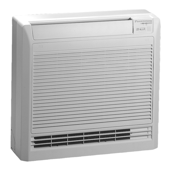
Instruction SiE12-411 Names of Parts FTK(X)E 25/35 B " Indoor Unit System Configuration... -
Page 124: Indoor Unit
SiE12-411 Instruction " Oudoor Unit " Indoor Unit 1. Air filter 12. Indoor Unit ON/OFF switch: 2. Photocatalytic deodorizing filter or • Push this switch once to start operation. Air purifying filter: Push once again to stop it. • These filters are attached to the inside of •... - Page 125 Instruction SiE12-411 " Remote control HOME LEAVE ON/OFF TEMP POWERFUL MODE SWING SILENT SENSOR CANCEL TIMER < > ARC433A1, A2 1. Signal transmitter: 8. SILENT button: for OUTDOOR UNIT SILENT • It sends signals to the indoor unit. operation 2. Display: •...
- Page 126 SiE12-411 Instruction FTK(X)D 50/60/71 B " Indoor Unit " Main unit control panel System Configuration...
- Page 127 Instruction SiE12-411 " Oudoor Unit " Indoor Unit 1. Air filter 13. HOME LEAVE lamp (red): 2. Photocatalytic deodorizing filter or • Lights up when you use HOME LEAVE Air purifying filter: Operation. • These filters are attached to the inside of 14.
- Page 128 SiE12-411 Instruction " Remote control HOME LEAVE ON/OFF TEMP POWERFUL MODE SILENT SENSOR SWING CANCEL TIMER < > ARC433A21, A22 1. Signal transmitter: 8. SILENT button: for OUTDOOR UNIT SILENT • It sends signals to the indoor unit. operation 2. Display: 9.
- Page 129 Instruction SiE12-411 CDK(X)D 25/35/50/60 C " Indoor Unit System Configuration...
- Page 130 SiE12-411 Instruction " Oudoor Unit " Indoor Unit 1. Air filter 10. Indoor Unit ON/OFF switch: 2. Air outlet grille (Field supply) • Push this switch once to start operation. Appearance of the Air outlet grille and Air Push once again to stop it. inlet grille may differ with some models.
- Page 131 Instruction SiE12-411 " Remote control HOME LEAVE ON/OFF TEMP POWERFUL MODE SILENT CANCEL TIMER < > ARC433A7, A8 1. Signal transmitter: 7. MODE selector button: • It sends signals to the indoor unit. • It selects the operation mode. 2. Display: (AUTO/DRY/COOL/HEAT/FAN) •...
- Page 132 SiE12-411 Instruction FLK(X) 25/35/50/60 A " Indoor Unit The indoor unit can be installed either to the ceiling or to a wall. The descriptions contained in this manual show the case when installation is being carried out to the ceiling. (The methods of operation used are the same when installing to a wall.
- Page 133 Instruction SiE12-411 " Oudoor Unit " Indoor Unit 1. Louvres (vertical blades) 13. Indoor unit ON/OFF switch The louvres are inside of the air outlet. • Push this switch once to start operation. 2. Air outlet Push once again to stop it. 3.
-
Page 134: Remote Control
SiE12-411 Instruction " Remote control HOME LEAVE ON/OFF TEMP POWERFUL MODE SWING SILENT CANCEL TIMER < > ARC433A5, A6 1. Signal transmitter: 7. MODE selector button: • It sends signals to the indoor unit. • It selects the operation mode. 2. -
Page 135: Preparation Before Operation
Instruction SiE12-411 Preparation before Operation " To set the batteries 1. Press with a finger and slide the front cover to take it off. Position + and – correctly! 2. Set two dry batteries (AAA). 3. Set the front cover as before. ATTENTION "... - Page 136 SiE12-411 Instruction " To operate the remote control • To use the remote control, aim the transmitter at the indoor unit. If there is anything to block signals between the unit and the remote control, such as a curtain, the unit will not operate.
-
Page 137: To Set The Clock
Instruction SiE12-411 " To set the clock 1. Press “CLOCK button”. 0:00 is displayed. blinks. 2. Press “TIMER setting button” to set the clock to the present time. Holding down “ ” or “ ” button rapidly increases or decreases the time display. 3. -
Page 138: Auto · Dry · Cool · Heat · Fan Operation
SiE12-411 Instruction AUTO · DRY · COOL · HEAT · FAN Operation The air conditioner operates with the operation mode of your choice. From the next time on, the air conditioner will operate with the same operation mode. " To start operation 1. -
Page 139: To Change The Air Flow Rate Setting
Instruction SiE12-411 " To change the air flow rate setting 5. Press “FAN setting button”. DRY mode AUTO or COOL or HEAT or FAN mode Five levels of air flow rate setting from “ ” to “ ” plus “ ”... -
Page 140: Adjusting The Air Flow Direction
SiE12-411 Instruction Adjusting the Air Flow Direction FTK(X)E 25/35 B You can adjust the air flow direction to increase your comfort. " To adjust the horizontal blades (flaps) 1. Press “SWING button”. The display will light up and the flaps will begin to swing. - Page 141 Instruction SiE12-411 " To adjust the vertical blades (louvres) Hold the knob and move the louvres. (You will find a knob on the left-side and the right-side blades.) Notes on flaps and louvres angles • When “SWING button” is selected, the flaps swinging range depends on the operation mode.
- Page 142 SiE12-411 Instruction FTK(X)D 50/60/71 B You can adjust the air flow direction to increase your comfort. " To adjust the horizontal blades (flaps) 1. Press “SWING button”. The display will light up and the flaps will begin to swing. 2. When the flap have reached the desired position, press “SWING”...
- Page 143 Instruction SiE12-411 " To 3-D Airflow 1. 3. press “SWING button”: the “ ” “ ” display will light up and the flaps and louvres will move in turn. " To cancel 3-D Airflow 2. 4. press “SWING button” Notes on louvres angles "...
- Page 144 SiE12-411 Instruction FLK(X) 25/35/50/60 A You can adjust the air flow direction to increase your comfort. " To adjust the horizontal blade (flap) 1. Press “SWING button”. The display will light up and the flaps will begin to swing. 2. When the flaps have reached the desired position, press “SWING button”...
- Page 145 Instruction SiE12-411 " To adjust the vertical blades (louvres) • When adjusting the louvre, use a robust and stable stool and watch your steps carefully. Hold the knob and move the louvres. (You will find a knob on the left side and the right side blades.) Notes on flap and louvres angles •...
-
Page 146: Powerful Operation
SiE12-411 Instruction POWERFUL Operation POWERFUL operation quickly maximizes the cooling (heating) effect in any operation mode. You can get the maximum capacity. " To start POWERFUL operation 1. Press “POWERFUL button”. • POWERFUL operation ends in 20 minutes. Then the system automatically operates HOME LEAVE ON/OFF again with the settings which were used... -
Page 147: Outdoor Unit Silent Operation
Instruction SiE12-411 OUTDOOR UNIT SILENT Operation OUTDOOR UNIT SILENT operation lowers the noise level of the outdoor unit by changing the frequency and fan speed on the outdoor unit. This function is convenient during night. " To start OUTDOOR UNIT SILENT operation 1. -
Page 148: Home Leave Operation
SiE12-411 Instruction HOME LEAVE Operation HOME LEAVE operation is a function which allows you to record your preferred temperature and air flow rate settings. " To start HOME LEAVE operation 1. Press “HOME LEAVE button” . • The HOME LEAVE lamp lights up. 1, 2 HOME LEAVE ON/OFF... - Page 149 Instruction SiE12-411 " What’s the HOME LEAVE operation Is there a set temperature and air flow rate which is most comfortable, a set temperature and air flow rate which you use the most? HOME LEAVE operation is a function that allows you to record your favorite set temperature and air flow rate.
-
Page 150: Intelligent Eye Operation
SiE12-411 Instruction 2.10 INTELLIGENT EYE Operation FTK(X)E 25/35 B “INTELLIGENT EYE” is the infrared sensor which detects the human movement. " To start INTELLIGENT EYE operation 1. Press “SENSOR button”. " To cancel the INTELLIGENT EYE operation 2. Press “SENSOR button” again. HOME LEAVE ON/OFF [EX.]... - Page 151 Instruction SiE12-411 " To adjust the angle of the INTELLIGENT EYE sensor • You can adjust the angle of the INTELLIGENT EYE sensor to increase the detection area. (Adjustable angle: 15° to right and left of centre) INTELLIGENT EYE 15° 15° sensor •...
- Page 152 SiE12-411 Instruction FTK(X)D 50/60/71 B “INTELLIGENT EYE” is the infrared sensor which detects the human movement. " To start INTELLIGENT EYE operation 1. Press “SENSOR button”. " To cancel the INTELLIGENT EYE operation 2. Press “SENSOR button” again. HOME LEAVE ON/OFF [EX.] TEMP...
- Page 153 Instruction SiE12-411 “INTELLIGENT EYE” is useful for Energy Saving " Energy saving operation • Change the temperature –2°C in heating / +2°C in cooling / +1°C in dry mode from set temperature. • Decrease the air flow rate slightly in fan operation. (In FAN mode only) Notes on “INTELLIGENT EYE”...
-
Page 154: Timer Operation
SiE12-411 Instruction 2.11 TIMER Operation Timer functions are useful for automatically switching the air conditioner on or off at night or in the morning. You can also use OFF TIMER and ON TIMER in combination. " To use OFF TIMER operation •... -
Page 155: To Use On Timer Operation
Instruction SiE12-411 " To use ON TIMER operation • Check that the clock is correct. If not, set the clock to the present time. 1. Press “ON TIMER button”. 7:00 is displayed. blinks. 2. Press “TIMER Setting button” until the time setting reaches the point you like. -
Page 156: Note For Multi System
SiE12-411 Instruction 2.12 Note for Multi System << What is a “Multi System”? >> This system has one outdoor unit connected to multiple indoor units. " Selecting the Operation Mode 1. With the Priority Room Setting present but inactive or not present When more than one indoor unit is operating, priority is room Outdoor... -
Page 157: Priority Room Setting
Instruction SiE12-411 " Priority Room Setting The Priority Room Setting requires initial programming during installation. Please consult your retailer or dealer for assistance. The room designated as the Priority Room takes priority in the following situations; 1. Operation Mode Priority As the operation mode of the Priority Room takes precedence, the user can select a different operation mode from other rooms. -
Page 158: Care And Cleaning
SiE12-411 Instruction 2.13 Care and Cleaning FTK(X)E 25/35 B CAUTION Before cleaning, be sure to stop the operation and turn the breaker OFF. Units " Indoor unit, Outdoor unit and Remote control 1. Wipe them with dry soft cloth. " Front grille 1. -
Page 159: Air Filter
Instruction SiE12-411 Filters 1. Open the front grille. 2. Pull out the air filters. • Push a little upwards the tab at the center of each air filter, then pull it down. 3. Take off the air purifying filter, photocatalytic deodorizing filter. -
Page 160: Before A Long Idle Period
SiE12-411 Instruction Check Check that the base, stand and other fittings of the outdoor unit are not decayed or corroded. Check that nothing blocks the air inlets and the outlets of the indoor unit and the outdoor unit. Check that the earth wire is not disconnected or broken. Check that the drain comes smoothly out of the drain hose during COOL or DRY operation. -
Page 161: Front Grille
Instruction SiE12-411 FTK(X)D 50/60/71 B CAUTION Before cleaning, be sure to stop the operation and turn the breaker OFF. Units " Indoor unit, Outdoor unit and Remote control 1. Wipe them with dry soft cloth. " Front grille 1. Open the front grille. •... - Page 162 SiE12-411 Instruction Filters 1. Open the front grille. 2. Pull out the air filters. • Push a little upwards the tab at the center of each air filter, then pull it down. 3. Take off the air purifying filter with photocatalytic deodorizing function.
- Page 163 Instruction SiE12-411 Check Check that the base, stand and other fittings of the outdoor unit are not decayed or corroded. Check that nothing blocks the air inlets and the outlets of the indoor unit and the outdoor unit. Check that the earth wire is not disconnected or broken. Check that the drain comes smoothly out of the drain hose during COOL or DRY operation.
- Page 164 When using the unit in a location where dirt may easily accumulate, clean the unit more frequently. Once every 2 weeks is recommended. • Ask your DAIKIN dealer how to clean them. Cleaning the drain pan • Clean the drain pan periodically, or drain piping may be clogged with dust and may result in water leakage.
- Page 165 Instruction SiE12-411 FLK(X) 25/35/50/60 A CAUTION Before cleaning, be sure to stop the operation and turn the breaker OFF. Units " Indoor unit, Outdoor unit and Remote control 1. Wipe them with dry soft cloth. " Front grille 1. Open the front grille. •...
- Page 166 SiE12-411 Instruction Filters 1. Open the front grille. 2. Pull out the air filters. • Push upwards the tab at the center of each air filter, then pull it down. 3. Take off the air purifying filter, photocatalytic deodorizing filter. •...
- Page 167 Instruction SiE12-411 Check Check that the base, stand and other fittings of the outdoor unit are not decayed or corroded. Check that nothing blocks the air inlets and the outlets of the indoor unit and the outdoor unit. Check that the earth wire is not disconnected or broken. Check that the drain comes smoothly out of the drain hose during COOL or DRY operation.
-
Page 168: Troubleshooting
SiE12-411 Instruction 2.14 Troubleshooting These cases are not troubles. The following cases are not air conditioner troubles but have some reasons. You may just continue using it. Case Explanation Operation does not start soon. • This is to protect the air conditioner. •... -
Page 169: Check Again
Instruction SiE12-411 Check again. Please check again before calling a repair person. Case Check The air conditioner does not • Hasn’t a breaker turned OFF or a fuse blown? operate. • Isn’t it a power failure? (OPERATION lamp is off) •... -
Page 170: Call The Service Shop Immediately
SiE12-411 Instruction Call the service shop immediately. WARNING " When an abnormality (such as a burning smell) occurs, stop operation and turn the breaker OFF. Continued operation in an abnormal condition may result in troubles, electric shocks or fire. Consult the service shop where you bought the air conditioner. "... - Page 171 Instruction SiE12-411 System Configuration...
-
Page 172: Part 6 Service Diagnosis
SiE12-411 Part 6 Service Diagnosis 1. Caution for Diagnosis................162 1.1 Troubleshooting with the Operation Lamp ...........162 2. Problem Symptoms and Measures .............164 3. Service Check Function ..............165 4. Code Indication on the Remote Controller ..........166 4.1 Error Codes and Description of Fault ...........166 5. -
Page 173: Caution For Diagnosis
Caution for Diagnosis SiE12-411 1. Caution for Diagnosis Troubleshooting with the Operation Lamp The operation lamp flashes when any of the following errors is detected. 1. When a protection device of the indoor or outdoor unit is activated or when the thermistor malfunctions, disabling equipment operation. - Page 174 SiE12-411 Caution for Diagnosis Caution: Operation stops suddenly. (Operation lamp blinks.) Cause of above trouble could be "Operation mode butting". Check followings; Are the operation modes all the same for indoor units connected to Multi system outdoor unit? If not set all indoor units to the same operation mode and confirm that the operation lamp is not blinking.
-
Page 175: Problem Symptoms And Measures
Problem Symptoms and Measures SiE12-411 2. Problem Symptoms and Measures Problem Symptom Check Item Details of Measure Page to be referred None of the units operates. Check the power supply. Check to make sure that the rated voltage is — supplied. -
Page 176: Service Check Function
SiE12-411 Service Check Function 3. Service Check Function In the ARC433A series, the temperature display sections on the main unit indicate corresponding codes. 1. When the timer cancel button is held down for 5 seconds, a “00” indication flashes on the temperature display section. -
Page 177: Code Indication On The Remote Controller
Code Indication on the Remote Controller SiE12-411 4. Code Indication on the Remote Controller Error Codes and Description of Fault Code Indication Description of Problem System Normal Insufficient gas Low-voltage detection Signal transmission error (between indoor and outdoor units) Unspecified voltage (between indoor and outdoor units) Anti-icing function in other rooms Indoor Indoor unit PCB abnormality... -
Page 178: Troubleshooting
SiE12-411 Troubleshooting 5. Troubleshooting Indoor Units - : Not used for troubleshooting ∗ : Varies depending on the cases. Indication on Description of The Fault Details of fault the remote (Refer to the controller indicated page.) Indoor unit in normal condition (Conduct a diagnosis of the outdoor —... -
Page 179: Outdoor Units
Troubleshooting SiE12-411 Outdoor Units : ON, : OFF, : Blinks Green : Flashes when in normal condition Red : OFF in normal condition - : Not used for troubleshooting ∗ : Varies depending on the cases. Outdoor Unit LED Indication Indication on Description of The Fault Details of... -
Page 180: Indoor Unit Pcb Abnormality
SiE12-411 Troubleshooting Indoor Unit PCB Abnormality Remote Controller Display Method of Evaluation of zero-cross detection of power supply by indoor unit. Malfunction Detection Malfunction When there is no zero-cross detection in approximately 10 continuous seconds. Decision Conditions " Faulty indoor unit PCB Supposed "... -
Page 181: Freeze-Up Protection Control Or High Pressure Control
Troubleshooting SiE12-411 Freeze-up Protection Control or High Pressure Control Remote Controller Display " High pressure control (heat pump model only) Method of Malfunction During heating operations, the temperature detected by the indoor heat exchanger thermistor is used for the high pressure control (stop, outdoor fan stop, etc.) Detection "... - Page 182 SiE12-411 Troubleshooting Troubleshooting Be sure to turn off power switch before connect or disconnect connector, Caution or parts damage may be occurred. Check No.6 Check the air passage. Refer to P.207 Is there any Provide sufficient air passage. short-circuit? Check the intake air filter. Is it very dirty? Clean the air filter.
-
Page 183: Fan Motor Or Related Abnormality
Troubleshooting SiE12-411 Fan Motor or Related Abnormality 5.5.1 AC Motor Remote Controller Display Method of The rotation speed detected by the Hall IC during fan motor operation is used to determine Malfunction abnormal fan motor operation. Detection Malfunction When the detected rotation speed is less than 50% of the HH tap under maximum fan motor rotation demand. -
Page 184: Dc Motor
SiE12-411 Troubleshooting 5.5.2 DC Motor Remote Controller Display Method of The rotation speed detected by the Hall IC during fan motor operation is used to determine Malfunction abnormal fan motor operation. Detection Malfunction When the detected rotation speed is less than 50% of the H tap under maximum fan motor Decision rotation demand. - Page 185 Troubleshooting SiE12-411 Troubleshooting Be sure to turn off power switch before connect or disconnect connector, Caution or parts damage may be occurred. Check No.01 Turn off power supply Refer to P.204 and rotate fan by hand. Check No.02 Does fan rotate Replace fan motor.
-
Page 186: Thermistor Or Related Abnormality (Indoor Unit)
SiE12-411 Troubleshooting Thermistor or Related Abnormality (Indoor Unit) C4, C9 Remote Controller Display Method of The temperatures detected by the thermistors are used to determine thermistor errors. Malfunction Detection Malfunction When the thermistor input is more than 4.96 V or less than 0.04 V during compressor Decision operation∗. -
Page 187: Shutter Drive Motor / Shutter Limit Switch Abnormality
Troubleshooting SiE12-411 Shutter Drive Motor / Shutter Limit Switch Abnormality Remote Controller Display Method of The shutter open / close performance is detected by the limit switch attached on its structure. In this way, the shutter drive motor and the shutter limit switch are checked for failure. Malfunction Detection Malfunction... -
Page 188: Signal Transmission Error (Between Indoor And Outdoor Units)
SiE12-411 Troubleshooting Signal Transmission Error (between Indoor and Outdoor Units) Remote Controller Display Method of The data received from the outdoor unit in indoor unit-outdoor unit signal transmission is Malfunction checked whether it is normal. Detection Malfunction When the data sent from the outdoor unit cannot be received normally, or when the content of Decision the data is abnormal. -
Page 189: Unspecified Voltage (Between Indoor And Outdoor Units)
Troubleshooting SiE12-411 Unspecified Voltage (between Indoor and Outdoor Units) Remote Controller Display Method of The supply power is detected for its requirements (different from separate type and multi type) Malfunction by the indoor / outdoor transmission signal. Detection Malfunction The separate type and multi type are interconnected. Decision Conditions "... -
Page 190: Freeze-Up Protection Control
SiE12-411 Troubleshooting 5.10 Freeze-up Protection Control Remote Controller Display Outdoor Unit LED Display Method of Indoor unit icing, during cooling operation, is detected by checking the temperatures sensed by Malfunction the indoor unit heat exchanger thermistor and room temperature thermistor that are located in a shut-down room. - Page 191 Troubleshooting SiE12-411 Troubleshooting Be sure to turn off power switch before connect or disconnect connector, Caution or parts damage may be occurred. Check No.4 Check the wiring and piping. Refer to P.205 Check No.6 Wiring or piping out of spec? Activate the wiring error Refer to P.207 check mode.
-
Page 192: Ol Activation (Compressor Overload)
SiE12-411 Troubleshooting 5.11 OL Activation (Compressor Overload) Remote Controller Display Outdoor Unit LED Display Method of A compressor overload is detected through compressor OL. Malfunction Detection " If the compressor OL is activated twice, the system will be shut down. Malfunction "... -
Page 193: Compressor Lock
Troubleshooting SiE12-411 5.12 Compressor Lock Remote Controller Display Outdoor Unit LED Display Method of A compressor lock is detected by checking the compressor running condition through the Malfunction position detection circuit. Detection " The position detection circuit detects a compressor frequency of below 10 Hz for 20 seconds Malfunction Decision or a frequency of above 160 Hz. -
Page 194: Dc Fan Lock
SiE12-411 Troubleshooting 5.13 DC Fan Lock Remote Controller Display Outdoor Unit LED Display Method of A fan motor line error is detected by checking the high-voltage fan motor rpm being detected by Malfunction the Hall IC. Detection " The fan does not start in 30 seconds even when the fan motor is running. Malfunction "... -
Page 195: Input Over Current Detection
Troubleshooting SiE12-411 5.14 Input Over Current Detection Remote Controller Display Outdoor Unit LED Display Method of An input over-current is detected by checking the input current value being detected by CT with Malfunction the compressor running. Detection " The following CT input with the compressor running continues for 2.5 seconds. Malfunction Decision CT input : Above 20 A... - Page 196 SiE12-411 Troubleshooting Troubleshooting Be sure to turn off power switch before connect or disconnect connector, Caution or parts damage may be occurred. Check No.7 ∗ An input over-current may result from wrong internal wiring. If the wires have been disconnected and reconnected for part replacement, for example, and the system is interrupted by an input over-current, Refer to P.208 take the following procedure.
-
Page 197: Four Way Valve Abnormality
Troubleshooting SiE12-411 5.15 Four Way Valve Abnormality Remote Controller Display Outdoor Unit LED Display Method of The liquid pipe thermistor, the outdoor temperature thermistor and the outdoor unit heat Malfunction exchanger thermistor are checked to see if they function within their normal ranges in the operating mode. - Page 198 SiE12-411 Troubleshooting Troubleshooting Be sure to turn off power switch before connect or disconnect connector, Caution or parts damage may be occurred. Check No.5 Refer to P.206 Four-way valve coil Correct. disconnected (loose)? Check No.6 Refer to P.207 Harness out of connector? Reconnect.
-
Page 199: Discharge Pipe Temperature Control
Troubleshooting SiE12-411 5.16 Discharge Pipe Temperature Control Remote Controller Display Outdoor Unit LED Display Method of The discharge pipe temperature control (stop, frequency drooping, etc.) is checked with the Malfunction temperature being detected by the discharge pipe thermistor. Detection " If a stop takes place 6 times straight due to abnormal discharge pipe temperature, the Malfunction Decision system will be shut down. -
Page 200: Position Sensor Abnormality
SiE12-411 Troubleshooting 5.17 Position Sensor Abnormality Remote Controller Display Outdoor Unit LED Display Method of A compressor startup failure is detected by checking the compressor running condition through Malfunction the position detection circuit. Detection " The compressor fails to start in about 15 seconds after the compressor run command signal Malfunction Decision is sent. -
Page 201: Ct Or Related Abnormality
Troubleshooting SiE12-411 5.18 CT or Related Abnormality Remote Controller Display Outdoor Unit LED Display Method of A CT or related error is detected by checking the compressor running frequency and CT- Malfunction detected input current. Detection Malfunction The compressor running frequency is below 55 Hz and the CT input is below 0.1 V. Decision (The input current is also below 1.25 A.) "... - Page 202 SiE12-411 Troubleshooting Troubleshooting Be sure to turn off power switch before connect or disconnect connector, Caution or parts damage may be occurred. Check No.12 Turn off the power and turn it on again. Refer to P.211 Get the system started. ∗...
-
Page 203: Thermistor Or Related Abnormality (Outdoor Unit)
Troubleshooting SiE12-411 5.19 Thermistor or Related Abnormality (Outdoor Unit) P4, J3, J6, J8, J9, H9 Remote Controller Display Outdoor Unit LED Display Method of This type of error is detected by checking the thermistor input voltage to the microcomputer. Malfunction [A thermistor error is detected by checking the temperature being detected by each thermistor.] Detection Malfunction... - Page 204 SiE12-411 Troubleshooting Troubleshooting Be sure to turn off power switch before connect or disconnect connector, Caution or parts damage may be occurred. Check No.6 Turn on the power again. Refer to P.207 Error displayed again Reconnect. on remote controller? Connector or thermistor Reconnect.
-
Page 205: Electrical Box Temperature Rise
Troubleshooting SiE12-411 5.20 Electrical Box Temperature Rise Remote Controller Display Outdoor Unit LED Display Method of An electrical box temperature rise is detected by checking the radiation fin thermistor with the Malfunction compressor off. Detection Malfunction With the compressor off, the radiation fin temperature is above 80°C (above 75°C in the case of Decision 8.0 ·... - Page 206 SiE12-411 Troubleshooting Troubleshooting Be sure to turn off power switch before connect or disconnect connector, Caution or parts damage may be occurred. Check No.6 WARNING Turn off the power and turn it on Refer to P.207 again. To cool down the electricals, the outdoor unit fan gets started when the radiation fin temperature rises above 78°C and stops itself when...
-
Page 207: Radiation Fin Temperature Rise
Troubleshooting SiE12-411 5.21 Radiation Fin Temperature Rise Remote Controller Display Outdoor Unit LED Display Method of A radiation fin temperature rise is detected by checking the radiation fin temperature being Malfunction detected by the fin thermistor with the compressor on. Detection Malfunction If the radiation fin temperature with the compressor on is above 90°C for 5.2~7.5 kW-or-smaller... - Page 208 SiE12-411 Troubleshooting Troubleshooting Be sure to turn off power switch before connect or disconnect connector, Caution or parts damage may be occurred. Check No.6 Turn off the power and turn it on again to get the system started. Refer to P.207 Check No.7 Refer to P.208 Error displayed again?
-
Page 209: Output Over Current Detection
Troubleshooting SiE12-411 5.22 Output Over Current Detection Remote Controller Display Outdoor Unit LED Display Method of An output over-current is detected by checking the current that flows in the inverter DC section. Malfunction Detection " A position signal error occurs while the compressor is running. Malfunction "... - Page 210 SiE12-411 Troubleshooting Troubleshooting Be sure to turn off power switch before connect or disconnect connector, Caution or parts damage may be occurred. Check No.7 ∗ An output over-current may result from wrong internal wiring. If the wires have been disconnected and reconnected for part replacement, for example, and the system is interrupted by an output over-current, Refer to P.208 take the following procedure.
-
Page 211: Insufficient Gas
Troubleshooting SiE12-411 5.23 Insufficient Gas Remote Controller Display Outdoor Unit LED Display Method of Gas shortage detection I : A gas shortage is detected by checking the CT-detected input current Malfunction value and the compressor running frequency. Gas shortage detection II : A gas shortage is detected by checking the difference between Detection indoor unit heat exchanger temperature and room temperature as well as the difference between outdoor unit heat exchanger temperature and room temperature. - Page 212 SiE12-411 Troubleshooting Troubleshooting Be sure to turn off power switch before connect or disconnect connector, Caution or parts damage may be occurred. Check No.4 Refer to P.205 Any thermistor Reconnect in position. disconnected? * Discharge pipe thermistor * Indoor / outdoor unit heat exchanger thermistor * Room temperature thermistor Check No.6 * Outdoor air thermistor...
-
Page 213: Low-Voltage Detection
Troubleshooting SiE12-411 5.24 Low-voltage Detection Remote Controller Display Outdoor Unit LED Display Method of An abnormal voltage rise or drop is detected by checking the detection circuit or DC voltage Malfunction detection circuit. Detection " An over-voltage signal is fed from the over-voltage detection circuit to the microcomputer, or Malfunction Decision the voltage being detected by the DC voltage detection circuit is judged to be below 150 V... -
Page 214: Anti-Icing Function In Other Rooms / Unspecified Voltage (Between Indoor And Outdoor Units)
SiE12-411 Troubleshooting 5.25 Anti-icing Function in Other Rooms / Unspecified Voltage (between Indoor and Outdoor Units) UA, UH Remote Controller Display Outdoor Unit LED Display Method of A wrong connection is detected by checking the combination of indoor and outdoor units on the Malfunction microcomputer. -
Page 215: Check
Check SiE12-411 6. Check How to Check 6.1.1 Fan Motor Connector Output Check Check No.01 1. Check connector connection. 2. Check motor power supply voltage output (pins 4-7 and 4-8). 3. Check motor control voltage (pins 4-3). 4. Check rotation command voltage output (pins 4-2). 5. -
Page 216: Electronic Expansion Valve Check
SiE12-411 Check 6.1.3 Electronic Expansion Valve Check Check No.4 Conduct the followings to check the electronic expansion valve (EV). 1. Check to see if the EV connector is correctly inserted in the PCB. Compare the EV unit and the connector number. 2. -
Page 217: Four Way Valve Performance Check
Check SiE12-411 6.1.4 Four Way Valve Performance Check Check No.5 Turn off the power and turn it on again. ∗ Four way valve coil Cooling / dry : No continuity Start the heating-mode run. Heating : Continuity S80 voltage at DC 180-220 V with Replace the outdoor unit compressor on? PCB. -
Page 218: Thermistor Resistance Check
SiE12-411 Check 6.1.5 Thermistor Resistance Check Check No.6 Remove the connectors of the thermistors on the PCB, and measure the resistance of each thermistor using tester. The relationship between normal temperature and resistance is shown in the graph and the table below. -
Page 219: Installation Condition Check
Check SiE12-411 6.1.6 Installation Condition Check Check No.7 Installation condition check Check the allowable Abnormal dimensions of the air suction Change the position of the air and discharge discharge grille or the area. installation location. Normal Does the discharged air from other outdoor Change the position of the air unit cause an increase of discharge grille or the... -
Page 220: Discharge Pressure Check
SiE12-411 Check 6.1.7 Discharge Pressure Check Check No.8 Discharge pressure check High Replace compessor. Is the stop valve open? Open the stop valve. Is the connection pipe deformed? Replace the pipe installed at the site. At the heat exchanger and Clean. -
Page 221: Power Supply Waveforms Check
Check SiE12-411 6.1.9 Power Supply Waveforms Check Check No.10 Measure the power supply waveform between pins 1 and 3 on the terminal board, and check the waveform disturbance. " Check to see if the power supply waveform is a sine wave (Fig.1). "... -
Page 222: Capacitor Voltage Check
SiE12-411 Check 6.1.11 Capacitor Voltage Check Check No.12 Before this checking, be sure to check the main circuit for short-circuit. " Checking the capacitor voltage ! With the circuit breaker still on, measure the voltage according to the drawing of the model in question. -
Page 223: Main Circuit Electrolytic Capacitor Check
Check SiE12-411 6.1.13 Main Circuit Electrolytic Capacitor Check " Checking the main circuit electrolytic capacitor Check No.14 ! Never touch any live parts for at least 10 minutes after turning off the circuit breaker. ! If unavoidably necessary to touch a live part, make sure there is no DC voltage using the tester. -
Page 224: Hall Ic Check
SiE12-411 Check 6.1.15 Hall IC Check Check No.16 1. Check the connector connection. 2. With the power ON, operation OFF, and the connector connected, check the following. ∗Output voltage of about 5 V between pins 1 and 3. ∗Generation of 3 pulses between pins 2 and 3 when the fan motor is operating. Failure of (1) $ faulty PCB $ Replace the PCB. - Page 225 Check SiE12-411 Service Diagnosis...
-
Page 226: Part 7 Removal Procedure
SiE12-411 Part 7 Removal Procedure 1. Outdoor Unit (80 / 90 Class) ...............216 1.1 Removal of Outer Panels ..............216 1.2 Removal of Propeller Fans..............219 1.3 Removal of Electrical Box ..............220 1.4 Removal of PCB...................227 1.5 Removal of Fan Motor................230 1.6 Removal of Electronic Expansion Valve and Thermistor .....232 1.7 Removal of Sound Insulation and Reactor...........233 1.8 Removal of Shunt.................235 1.9 Removal of Solenoid Valve and Four Way Valve.........236... -
Page 227: Outdoor Unit (80 / 90 Class)
Outdoor Unit (80 / 90 Class) SiE12-411 1. Outdoor Unit (80 / 90 Class) Removal of Outer Panels Procedure Warning Be sure to wait 10 minutes or more after turning off all power supplies before disassembling work. Procedure Points Step External appearance. - Page 228 Outdoor Unit (80 / 90 Class) SiE12-411 Step Procedure Points Unscrew 3 screws of the right panel, slide it downwards and release the tabs to remove. Right panel (Main unit side) Tabs (Right panel side) The figure shows the PC board view of piping for servicing connections.
- Page 229 Outdoor Unit (80 / 90 Class) SiE12-411 Step Procedure Points Unscrew 3 screws of the front panel to remove. Remove 4 screws of the discharge outlet grill. Slide the discharge outlet grill upwards and release 6 tabs to Tabs remove. Tabs Removal Procedure...
-
Page 230: Removal Of Propeller Fans
Outdoor Unit (80 / 90 Class) SiE12-411 Removal of Propeller Fans Procedure Warning Be sure to wait 10 minutes or more after turning off all power supplies before disassembling work. Step Procedure Points " Remove the discharge outlet grill To take off propeller fan, remove the washer-fitted nut M8. -
Page 231: Removal Of Electrical Box
Outdoor Unit (80 / 90 Class) SiE12-411 Removal of Electrical Box Procedure Warning Be sure to wait 10 minutes or more after turning off all power supplies before disassembling work. Step Procedure Points " Remove the outer panels " Match the colors of the tie such as top and front wires to A, B, C and D ports panels. - Page 232 Outdoor Unit (80 / 90 Class) SiE12-411 Step Procedure Points Remove the earth wire. Remove 1 screw of the terminal board. Release the tab on the top right of the terminal board. " Glass tube fuse and varistor Pull out the terminal Glass tube fuse (Soldered) board and open it.
- Page 233 Outdoor Unit (80 / 90 Class) SiE12-411 Step Procedure Points 2. Remove each wire harness Disconnect 4 connectors of the white blue yellow electronic expansion Connector Electronic Harness expansion length valve lead wires. valve No. S20 (White) S21 (Red) S22 (Blue) S23 (Yellow) "...
- Page 234 Outdoor Unit (80 / 90 Class) SiE12-411 Step Procedure Points Remove the connector S92 for gas pipe thermistor. Remove the connector S90 for thermistor. " Outdoor air thermistor (Blue) " Discharge pipe thermistor (Black) " Heat exchanger thermistor (Gray) Remove the overload relay connector S40.
- Page 235 Outdoor Unit (80 / 90 Class) SiE12-411 Step Procedure Points Remove the relay connector for compressor. Relay connector for compressor Remove the electrical box cover. Electrical box cover Disconnect the fan motor connector. Remove the discharge pipe thermistor. Removal Procedure...
- Page 236 Outdoor Unit (80 / 90 Class) SiE12-411 Step Procedure Points " Place the thermistor so that Take off the thermistor Thermistor presser spring presser spring, and its end comes up to the end remove the thermistor. of the presser spring. "...
- Page 237 Outdoor Unit (80 / 90 Class) SiE12-411 Step Procedure Points Remove the outdoor air thermistor lead wire from the groove. Remove each wire Electrical box harness, and dismount the electrical box by lifting it. Removal Procedure...
-
Page 238: Removal Of Pcb
Outdoor Unit (80 / 90 Class) SiE12-411 Removal of PCB Procedure Warning Be sure to wait 10 minutes or more after turning off all power supplies before disassembling work. Step Procedure Points 1. Removing the controller Release the tab of the electrical box, and open the terminal board. - Page 239 Outdoor Unit (80 / 90 Class) SiE12-411 Step Procedure Points Lift the PCB at the terminal board side. Disconnect each wire harness connector linked to the inverter PCB. Removal Procedure...
- Page 240 Outdoor Unit (80 / 90 Class) SiE12-411 Step Procedure Points The figure shows the S20: Electronic expansion valve controller PCB. coil A port S21: Electronic expansion valve coil B port S22: Electronic expansion valve coil C port S23: Electronic expansion valve coil D port S31: To CN14 (Pin 9) S32: To CN11 (Pin 5)
-
Page 241: Removal Of Fan Motor
Outdoor Unit (80 / 90 Class) SiE12-411 Removal of Fan Motor Procedure Warning Be sure to wait 10 minutes or more after turning off all power supplies before disassembling work. Step Procedure Points " Remove the outer panels. Remove the fan motor lead wire connector S70. - Page 242 Outdoor Unit (80 / 90 Class) SiE12-411 Step Procedure Points Remove 4 screws of the fan motor. Cut the wrapper fixing the lead wire. " When reassembling, fix the lead wire to avoid contact with the propeller fan. Remove the fan motor. Removal Procedure...
-
Page 243: Removal Of Electronic Expansion Valve And Thermistor
Outdoor Unit (80 / 90 Class) SiE12-411 Removal of Electronic Expansion Valve and Thermistor Procedure Warning Be sure to wait 10 minutes or more after turning off all power supplies before disassembling work. Step Procedure Points " Place the thermistor so that Remove each wire harness. -
Page 244: Removal Of Sound Insulation And Reactor
Outdoor Unit (80 / 90 Class) SiE12-411 Removal of Sound Insulation and Reactor Procedure Warning Be sure to wait 10 minutes or more after turning off all power supplies before disassembling work. Step Procedure Points Release the clip fixing the compressor lead wire. - Page 245 Outdoor Unit (80 / 90 Class) SiE12-411 Step Procedure Points " Carefully remove the noise Remove the noise insulation (top). insulation, which is easily torn in the piping section. Noise insulation (top) Remove the noise insulation (inner). Noise insulation (inner) Remove 1 screw of the reactor.
-
Page 246: Removal Of Shunt
Outdoor Unit (80 / 90 Class) SiE12-411 Removal of Shunt Procedure Warning Be sure to wait 10 minutes or more after turning off all power supplies before disassembling work. Step Procedure Points " Fasten the rubber packing Remove 6 screws of the tie wire presser with double-faced adhesive plate. -
Page 247: Removal Of Solenoid Valve And Four Way Valve
Outdoor Unit (80 / 90 Class) SiE12-411 Removal of Solenoid Valve and Four Way Valve Procedure Warning Be sure to wait 10 minutes or more after turning off all power supplies before disassembling work. Step Procedure Points " Remove the outer panels. 1. - Page 248 Outdoor Unit (80 / 90 Class) SiE12-411 Step Procedure Points " Before taking this Reassembling precautions procedure, make sure 1. Use non-oxidizing brazing there is no refrigerant gas method. If nitrogen gas is not left in the refrigerant available, braze the parts pipes.
-
Page 249: Removal Of Compressor
Outdoor Unit (80 / 90 Class) SiE12-411 1.10 Removal of Compressor Procedure Warning Be sure to wait 10 minutes or more after turning off all power supplies before disassembling work. Step Procedure Points Remove the terminal cover. U (red) (brown) Terminal cover W (blue) V (yellow) - Page 250 Outdoor Unit (80 / 90 Class) SiE12-411 Step Procedure Points " Make sure there is no refrigerant gas left inside Warning the refrigerant pipes The compressor's refrigerating before starting the job. Putty machine oil may catch fire. Have " When heating up the wet cloth at hand for quickly putting brazed parts, make sure out the fire.
-
Page 251: Outdoor Unit (50 / 52 / 58 / 68 / 75 Class)
Outdoor Unit (50 / 52 / 58 / 68 / 75 Class) SiE12-411 2. Outdoor Unit (50 / 52 / 58 / 68 / 75 Class) Removal of Outer Panels Procedure Warning Be sure to wait 10 minutes or more after turning off all power supplies before disassembling work. -
Page 252: Removal Of Electrical Box
Outdoor Unit (50 / 52 / 58 / 68 / 75 Class) SiE12-411 Removal of Electrical BOX Procedure Warning Be sure to wait 10 minutes or more after turning off all power supplies before disassembling work. Step Procedure Points 1. Removing the tie wires The figure shows the tie Service monitor PCB pipe connections. - Page 253 Outdoor Unit (50 / 52 / 58 / 68 / 75 Class) SiE12-411 Step Procedure Points " Glass tube fuse and varistor Pull out the terminal board to open. cannot be replaced Glass tube fuse individually because lead- free soldering is provided. Varister Terminal board...
- Page 254 Outdoor Unit (50 / 52 / 58 / 68 / 75 Class) SiE12-411 Step Procedure Points Disconnect the compressor relay connector. Remove the reactor lead wire. Reactor 3. Removing the wiring fixture Remove 6 screws of the wiring fixture. Wiring fixture 4.
- Page 255 Outdoor Unit (50 / 52 / 58 / 68 / 75 Class) SiE12-411 Step Procedure Points Remove 1 screw of the electrical box. Remove the drip-proof cover. Drip-proof cover Disconnect the fan motor lead wire. Lift up the electrical box and dismount it.
-
Page 256: Removal Of Pcb
Outdoor Unit (50 / 52 / 58 / 68 / 75 Class) SiE12-411 Removal of PCB Procedure Warning Be sure to wait 10 minutes or more after turning off all power supplies before disassembling work. Step Procedure Points 1. Removing the controller Remove 1 screw of the PCB, and release two tabs. - Page 257 Outdoor Unit (50 / 52 / 58 / 68 / 75 Class) SiE12-411 Step Procedure Points Lift up the control PCB. Disconnect each wire harness connector linked to the control PCB. S31 (Pin 9): To CN14 S32 (Pin 5): To CN11 S33 (Pin 10): To S34 H1 (yellow) S71 (Pin 8): To S72...
- Page 258 Outdoor Unit (50 / 52 / 58 / 68 / 75 Class) SiE12-411 Step Procedure Points " Glass tube fuse 3A The figure shows the control PCB. Varistor S40 S6 2. Removing the service monitor PCB The figure shows the service monitor PCB.
-
Page 259: Removal Of Fan Motor
Outdoor Unit (50 / 52 / 58 / 68 / 75 Class) SiE12-411 Removal of Fan Motor Procedure Warning Be sure to wait 10 minutes or more after turning off all power supplies before disassembling work. Step Procedure Points " Remove the fan motor "... -
Page 260: Removal Of Sound Insulation
Outdoor Unit (50 / 52 / 58 / 68 / 75 Class) SiE12-411 Removal of Sound Insulation Procedure Warning Be sure to wait 10 minutes or more after turning off all power supplies before disassembling work. Step Procedure Points Remove 5 screws of the right side panel. -
Page 261: Removal Of Four Way Valve Coil, Solenoid Valve Coil, Electronic Expansion Valve Coil And Thermistor
Outdoor Unit (50 / 52 / 58 / 68 / 75 Class) SiE12-411 Removal of Four Way Valve Coil, Solenoid Valve Coil, Electronic Expansion Valve Coil and Thermistor Procedure Warning Be sure to wait 10 minutes or more after turning off all power supplies before disassembling work. - Page 262 Outdoor Unit (50 / 52 / 58 / 68 / 75 Class) SiE12-411 Step Procedure Points " Place the thermistor so that Take off the putty, and remove each its end comes up to the end thermistor. of the presser spring. "...
-
Page 263: Removal Of Four Way Valve, Solenoid Valve And Shunt
Outdoor Unit (50 / 52 / 58 / 68 / 75 Class) SiE12-411 Removal of Four Way Valve, Solenoid Valve and Shunt Procedure Warning Be sure to wait 10 minutes or more after turning off all power supplies before disassembling work. Step Procedure Points... -
Page 264: Removal Of Solenoid Valve And Shunt
Outdoor Unit (50 / 52 / 58 / 68 / 75 Class) SiE12-411 Removal of Solenoid Valve and Shunt Procedure Warning Be sure to wait 10 minutes or more after turning off all power supplies before disassembling work. Step Procedure Points "... -
Page 265: Removal Of Compressor
Outdoor Unit (50 / 52 / 58 / 68 / 75 Class) SiE12-411 Removal of Compressor Procedure Warning Be sure to wait 10 minutes or more after turning off all power supplies before disassembling work. Step Procedure Points Remove the terminal cover. -
Page 266: Part 8 Others
SiE12-411 Part 8 Others 1. Others ....................256 1.1 Test Run from the Remote Controller ..........256 1.2 Jumper Settings ...................257 Others... -
Page 267: Others
Others SiE12-411 1. Others Test Run from the Remote Controller Trial Operation and Testing 1. Measure the supply voltage and make sure that it falls in the specified range. 2. Trial operation should be carried out in either cooling or heating mode. For Heat pump In cooling mode, select the lowest programmable temperature;... -
Page 268: Jumper Settings
SiE12-411 Others Jumper Settings 1.2.1 When Two Units are Installed in One Room " How to set the different addresses. " When two indoor units are installed in one room, the two wireless remote controllers can be set for different addresses. PCB in the indoor unit "... - Page 269 Others SiE12-411 1.2.3 Adjusting the Angle of the Intelligent Eye Sensor Wall Mounted Type 25 / 35 Class Only " Once installation of the indoor unit is complete, adjust the angle of the Intelligent eye sensor to ensure the detection area properly covers the room. (Adjustable angle : 15°...
-
Page 270: Part 9 Appendix
SiE12-411 Part 9 Appendix 1. Piping Diagrams..................260 1.1 Indoor Units ..................260 1.2 Outdoor Units ..................266 2. Wiring Diagrams..................273 2.1 Indoor Units ..................273 2.2 Outdoor Units ..................276 Appendix... -
Page 271: Piping Diagrams
Piping Diagrams SiE12-411 1. Piping Diagrams Indoor Units 1.1.1 Wall Mounted Type FTKE25/35BVM, FTK(X)E25/35BVMA INDOOR UNIT HEAT EXCHANGER 7.0CuT 6.4CuT THERMISTOR 6.4CuT ON HEAT EXCH. 6.4CuT CROSS FLOW FAN FIELD PIPING ( 6.4CuT ) FTXE25-- FTKE25-- FAN MOTOR FIELD PIPING 9.5CuT FTXE35-- 12.7... - Page 272 SiE12-411 Piping Diagrams FTKD50BVM, FTK(X)D50BVMA, FTK(X)S50/60BVMB, FTXS50/60BVMA, ATXS50CVMB INDOOR UNIT ( 7.9CuT ) HEAT EXCHANGER THERMISTOR ON HEAT EXCH. CROSS FLOW FAN FIELD PIPING ( 6.4CuT ) FAN MOTOR FIELD PIPING ( 12.7CuT ) ( 12.7CuT ) REFRIGERANT FLOW COOLING 4D040081E HEATING FTKD60BVM, FTK(X)D60BVMA, FTK(X)S71BVMB, FTXS71BVMA...
- Page 273 Piping Diagrams SiE12-411 FTKD71BVM, FTK(X)D71BVMA INDOOR UNIT ( 7.9CuT ) HEAT EXCHANGER THERMISTOR ON HEAT EXCH. CROSS FLOW FAN FIELD PIPING ( 9.5CuT ) REFRIGERANT FLOW FAN MOTOR COOLING FIELD PIPING ( 15.9CuT ) HEATING ( 12.7CuT ) 4D040083C Appendix...
- Page 274 SiE12-411 Piping Diagrams 1.1.2 Duct Connected Type CDKD25/35/50/60CVM, CDK(X)D25/35/50/60CVMA INDOOR UNIT ( 6.4CuT ) HEAT EXCHANGER CDXD25CVMA CDKD25CVMA CDKD25CVM THERMISTOR CDXD35CVMA ON HEAT CDKD35CVMA FIELD PIPING EXCH. CDKD35CVM ( 6.4CuT ) SIROCCO FAN 12.7 12.7 CDKD50CVMA CDXD50CVMA CDKD50CVM FAN MOTOR CDXD60CVMA FIELD PIPING CuT )
- Page 275 Piping Diagrams SiE12-411 1.1.3 Floor / Ceiling Suspended Dual Type FLK(X)S25/35/50/60BVMB, FLXS25/35/50/60BVMA INDOOR UNIT CuT ) HEAT EXCHANGER THERMISTOR ON HEAT FIELD PIPING EXCH. SIROCCO FAN ( 6.4CuT ) FLX25 , 35- FLK25 , 35- FLXS25 , 35- FAN MOTOR FLKS25 , 35- FLX50 , 60- FIELD PIPING...
- Page 276 SiE12-411 Piping Diagrams 1.1.4 Floor Standing Type FVK(X)S25/35BVMB, FVXS35BVMA INDOOR UNIT HEAT EXCHANGER THERMISTOR CROSS FLOW FAN FAN MOTOR ON HEAT EXCH. 7.0CuT 7.0CuT CROSS FLOW FAN FAN MOTOR FIELD PIPING ( 6.4CuT ) SINGLE UNION JOINT 9.5CuT FIELD PIPING ( 9.5CuT ) SINGLE UNION JOINT REFRIGERANT FLOW...
-
Page 277: Outdoor Units
Piping Diagrams SiE12-411 Outdoor Units 1.2.1 Cooling Only 2MKD58BVM OUTDOOR UNIT HEAT EXCHANGER OUTDOOR TEMPERATURE THERMISTOR ( DOA ) HEADER MOTOR OPERATED VALVE 9.5CuT 6.4CuT ROOM A ( 6.4 CuT ) FILTER FIELD FILTER PIPING HEAT EXCHANGER MOTOR OPERATED VALVE LIQUID THERMISTOR ( DE ) DISTRIBUTOR... - Page 278 SiE12-411 Piping Diagrams 3MKD75BVM, 3MKD75BVMA OUTDOOR UNIT HEAT EXCHANGER OUTDOOR TEMPERATURE THERMISTOR ( DOA ) MOTOR OPERATED VALVE HEADER 6.4CuT 9.5CuT ROOM A ( 6.4 CuT ) FILTER MOTOR OPERATED VALVE 6.4CuT FIELD ROOM B FILTER PIPING ( 9.5 CuT ) HEAT EXCHANGER FILTER LIQUID...
- Page 279 Piping Diagrams SiE12-411 4MKD90BVM, 4MKD90BVMA OUTDOOR UNIT MOTOR OPERATED VALVE HEAT EXCHANGER OUTDOOR TEMPERATURE THERMISTOR ( DOA ) HEADER 7.9CuT ROOM A 7.9CuT ( 6.4 CuT ) FILTER MOTOR OPERATED VALVE 7.9CuT 7.9CuT 7.9CuT ROOM B 7.9CuT ( 6.4 CuT ) 7.9CuT FILTER FIELD...
- Page 280 SiE12-411 Piping Diagrams 4MKS58BVMB(8) OUTDOOR UNIT HEAT EXCHANGER OUTDOOR TEMPERATURE THERMISTOR ( DOA ) MOTOR OPERATED VALVE LIQUID PIPE THERMISTOR ( DLA ) 6.4CuT HEADER 9.5CuT ROOM A ( 6.4 CuT ) FILTER MOTOR OPERATED VALVE LIQUID PIPE THERMISTOR ( DLB ) 6.4CuT ROOM B ( 6.4 CuT )
- Page 281 Piping Diagrams SiE12-411 4MKS90BVMB OUTDOOR UNIT OUTDOOR TEMPERATURE MOTOR OPERATED VALVE HEAT EXCHANGER LIQUID PIPE THERMISTOR ( DOA ) THERMISTOR ( DLA ) 7.9CuT HEADER ROOM A 7.9CuT ( 6.4 CuT ) FILTER MOTOR OPERATED VALVE LIQUID PIPE 7.9CuT THERMISTOR ( DLB ) 7.9CuT 7.9CuT ROOM B...
-
Page 282: Heat Pump
SiE12-411 Piping Diagrams 1.2.2 Heat Pump 3MXS52BVMB(8), 3AMXS52BVMB OUTDOOR UNIT HEAT EXCHANGER OUTDOOR TEMPERATURE THERMISTOR ( DOA ) HEADER HEADER MOTOR OPERATED VALVE 9.5CuT LIQUID PIPE THERMISTOR ( DLA ) 6.4CuT ROOM A ( 6.4 CuT ) FILTER MOTOR OPERATED VALVE LIQUID PIPE THERMISTOR ( DLB ) 6.4CuT... - Page 283 Piping Diagrams SiE12-411 4MXS68BVMB9 OUTDOOR UNIT HEAT EXCHANGER OUTDOOR TEMPERATURE THERMISTOR ( DOA ) MOTOR OPERATED VALVE HEADER LIQUID PIPE THERMISTOR ( DLA ) HEADER 6.4CuT 9.5CuT ROOM A ( 6.4 CuT ) FILTER MOTOR OPERATED VALVE LIQUID PIPE THERMISTOR ( DLB ) 6.4CuT ROOM B ( 6.4 CuT )
-
Page 284: Wiring Diagrams
SiE12-411 Wiring Diagrams 2. Wiring Diagrams Indoor Units 2.1.1 Wall Mounted Type FTKE25/35BVM, FTK(X)E25/35BVMA FTK(X)S20CVMB(9), FTK(X)S25/35CVMB(9)(8), ATXS20/25/35CVMB(9), FTXS25/35BVMA PCB3 PCB1 → INTELLIGENT- 3.15A EYE SENSOR outdoor TERMINAL FOR PCB2 FIELD WIRING. / YLW CENTRALIZED CONTROL TRANSMISSION LED1 LED2 LED3 CIRCUIT CAUTION NOTE THAT OPERATION WILL RESTART AUTOMATICALLY IF... - Page 285 Wiring Diagrams SiE12-411 FTKD50/60/71BVM, FTK(X)D50/60/71BVMA FTK(X)S60/71BVMB, FTXS60/71BVMA FIELD WIRING. PCB3 PCB1 RECTIFIER 3.15A OUTDOOR t° CAUTION TRANSMISSION NOTE THAT OPERATION WILL CIRCUIT RESTART AUTOMATICALLY IF THE MAIN POWER SUPPLY IS PCB4 TURNED OFF AND THEN BACK ON AGAIN. LED1 LED2 LED3 : FRAME GROUND : FUSE...
- Page 286 SiE12-411 Wiring Diagrams 2.1.3 Floor / Ceiling Suspended Dual Type FLK(X)25/35/50/60AVMA, FLK(X)S25/35/50/60BVMB, FLXS25/35/50/60BVMA PCB3 PCB1 PCB2 3.15A → outdoor FIELD WIRING. / YLW PCB4 TRANSMISSION CIRCUIT CAUTION NOTE THAT OPERATION WILL SIGNAL RESTART AUTOMATICALLY IF RECEIVER THE MAIN POWER SUPPLY IS indoor TURNED OFF AND THEN BACK ON AGAIN.
-
Page 287: Outdoor Units
Wiring Diagrams SiE12-411 Outdoor Units 2.2.1 Cooling only 2MKD58BVM POWER SUPPLY FU201 ~ 50Hz 220-240V MID2 ~ 60Hz 220-230V 3.15A FIELD WIRING MRM20 MRM10 X11A TO INDOOR UNIT CN11 ROOM A R12T MID1 CN14 3.15A t° ROOM B 1 S40 S101 t°... - Page 288 SiE12-411 Wiring Diagrams 4MKD75/90BVM, 4MKD90BVMA POWER SUPPLY FU201 ~ 50Hz 220-240V MID2 ~ 60Hz 220-230V 3.15A FIELD WIRING MRM20 MRM10 X11A TO INDOOR UNIT CN11 ROOM A R12T MID1 CN14 3.15A t° ROOM B ROOM C S101 ROOM D t° t°...
- Page 289 Wiring Diagrams SiE12-411 4MKS58BVMB(8), 4MKS75BVMB, 4MKS90BVMB POWER SUPPLY FU201 ~ 50Hz 220-240V MID2 ~ 60Hz 220-230V 3.15A FIELD WIRING MRM20 MRM10 X11A TO INDOOR UNIT CN11 ROOM A MID1 R12T CN14 3.15A t° ROOM B ROOM C S101 ROOM D t°...
- Page 290 SiE12-411 Wiring Diagrams 2.2.2 Heat Pump 3MXD68BVMA, 3MXS52BVMB(8), 3AMXS52BVMB POWER SUPPLY FU201 MID2 ~ 50Hz 220-240V 3.15A ~ 60Hz 220-230V FIELD WIRING MRM20 MRM10 X11A TO INDOOR UNIT CN11 ROOM A MID1 R12T CN14 3.15A t° ROOM B ROOM C S101 t°...
- Page 291 Wiring Diagrams SiE12-411 4MXS80CVMA FU201 MID2 3.15A FIELD WIRING MRM20 MRM10 X11A TO INDOOR UNIT ROOM A CN11 MID1 R12T CN14 3.15A t° ROOM B ROOM C S101 ROOM D t° t° t° t° t° t° t° t° t° t° t°...
- Page 292 SiE12-411 Index Numerics e7 ................. 183 e8 ................. 184 3 minutes stand-by..........91 ea ................. 186 3-d airflow..............72 electrical box ..........220, 241 electrical box temperature rise ......194 electronic expansion valve ........232 a1 ................169 electronic expansion valve check......205 a5 ..............170, 179 electronic expansion valve coil......
- Page 293 SiE12-411 outdoor heat exchanger thermistor ....84, 86 outdoor unit fan system check (with dc motor)..209 indoor heat exchanger thermistor .....85, 87 outdoor unit silent operation ......... 136 indoor liquid pipe thermistor ........85 outer panels ..........216, 240 indoor unit pcb abnormality ........169 output over current detection .......
- Page 294 SiE12-411 s38 ................61 s40 ..........68, 223, 229, 242 wide-angle louvers ..........72 s6 ............58, 61, 64, 66 wiring diagrams ............ 273 s7 ............58, 63, 64, 66 wiring-error check..........103 s70 ................230 s71 ............68, 229, 246 s8 ..............61, 64, 66 s80 ..........68, 222, 229, 242 s90 ..........68, 223, 229, 242, 251 s92 ..........68, 223, 229, 242, 251 s93 ..........68, 222, 229, 242, 251...
- Page 295 SiE12-411 Index...
- Page 296 SiE12-411 Drawings & Flow Charts input over current detection........184 installation condition check ........208 anti-icing function in other rooms ......203 insufficient gas ............. 200 automatic air flow control ........73 insufficient gas control.......... 101 automatic operation..........75 intelligent eye ............77 auto-swing...............72 intelligent eye sensor pcb........
- Page 297 SiE12-411 thermistor resistance check ........207 troubleshooting with the led indication ....163 turning speed pulse input on the outdoor unit pcb check........212 unspecified voltage (between indoor and outdoor units) ........178 wiring diagrams .............273 wiring-error check..........103 Drawings & Flow Charts...
- Page 298 Daikin Europe N.V. is approved by LRQA for its Quality Daikin units comply with the European regulations that Management System in accordance with the ISO9001 guarantee the safety of the product. standard. ISO9001 pertains to quality assurance regarding design, development, manufacturing as well as to services related to the product.