Table of Contents
XI581AH / XI582AH
BUSWIDE OPERATOR INTERFACE
USER GUIDE
Software License Advisory
This document supports software that is proprietary to Honeywell Inc. and/or to
third-party software vendors. Before software delivery, the end user must execute
a software license agreement that governs software use. Software license agree-
ment provisions include limiting use of the software to equipment furnished,
limiting copying, preserving confidentiality, and prohibiting transfer to a third party.
Disclosure, use, or reproduction beyond that permitted in the license agreement is
prohibited.
Copyright © 2000 Honeywell Inc. • All Rights Reserved
EN2B-0126GE51 R1000 (74-3554-8)
Table of Contents

Related Manuals for Honeywell XI581AH


Summary of Contents for Honeywell XI581AH
- Page 1 BUSWIDE OPERATOR INTERFACE USER GUIDE Software License Advisory This document supports software that is proprietary to Honeywell Inc. and/or to third-party software vendors. Before software delivery, the end user must execute a software license agreement that governs software use. Software license agree- ment provisions include limiting use of the software to equipment furnished, limiting copying, preserving confidentiality, and prohibiting transfer to a third party.
- Page 2 XI581/2 BUSWIDE OPERATOR INTERFACE Trademark Information Echelon, LON, L , LonBuilder, NodeBuilder, LonManager, ORKS LonTalk, LonUsers, LonPoint, Neuron, 3120, 3150, the Echelon logo, the L logo, and the LonUsers logo are trademarks of Echelon Corporation registered in the United States and other countries. LonLink, LonResponse, LonSupport, and LonMaker are trademarks of Echelon Corporation.
-
Page 3: Table Of Contents
XI581/2 BUSWIDE OPERATOR INTERFACE CONTENTS Revision information ..................................ii INTRODUCTION .................................... 1 Manual Organization....................2 GETTING STARTED ..................................3 Connection Options ....................3 Buswide Access Mode ..................5 Screen Displays ......................8 Display Area Description................... 9 Display Window ....................9 Keypad ....................... -
Page 4: Revision Information
CONTENTS XI581/2 BUSWIDE OPERATOR INTERFACE Modifying the GSM PIN ..................66 Parameters ......................66 Passwords ......................67 Remote Communication ..................69 System Clock......................70 Template Operations ....................71 Adding a Template ..................... 71 Deleting a Template ................... 73 Modifying a Template ..................74 Test Options ...................... -
Page 5: Introduction
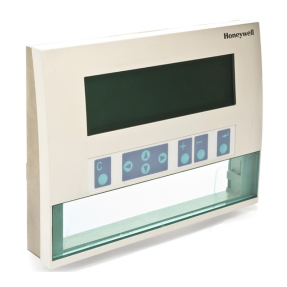
The XI581AH (Fig. 1) and XI582AH (Fig. 2) look and operate very much alike. The difference is that the XI581AH mounts directly on the front of an Excel 500 or 600 Controller, while the XI582AH is a desktop unit that you can place up to 50 ft. (15 m) away from an Excel controller or mount on a wall. -
Page 6: Manual Organization
The Introduction section briefly describes the XI581/2 and highlights similarities and differences between the two operator terminal models. The Getting Started section describes: • XI582AH connection to an Excel controller. (The XI581AH is mounted directly on an Excel controller at installation time.) • Buswide access mode. -
Page 7: Getting Started
Connection Options Connecting the XI581AH The XI581AH mounts on the front of an Excel 500 or 600 Controller at installation time and requires no further connection. When the Controller is powered, the XI581AH is also powered. If the Controller is off and then powered on, the XI581AH displays a message about the power failure. - Page 8 GETTING STARTED XI581/2 BUSWIDE OPERATOR INTERFACE connected to the rear terminals. If the switch is set to “front port“, the rear terminals are deactivated, and vice versa. • Excel 500 and 600 Controllers have the serial port connection at the top of the controller as shown in the following diagram.
-
Page 9: Buswide Access Mode
XI581/2 BUSWIDE OPERATOR INTERFACE GETTING STARTED EXCEL 50 SERIAL PORT EXCEL 500-XCL5010 (REAR VIEW) Fig. 5. Excel 50 and Excel 500-XCL5010 MMI connection. • Excel 10 Zone Manager and Excel 100B Controllers have a serial port connec- tion at the bottom of the device as shown in the following diagram. The XI581/2 reads the data for the Excel 10 Controllers that connect to the Excel 10 Zone Manager. - Page 10 Remote Excel Excel Controller Controller Buswide Access XI581AH/ XI582AH Fig. 7. Buswide access. Connection capabilities depend on the version of the controller and whether it has buswide access mode software. Table 2 specifies the versions capable of buswide access. There are two buswide access modes (active and passive) for controllers that have this capability.
- Page 11 XI581AH/ XI582AH Fig. 9. Passive buswide access. To access a remote controller, you must first log in to the controller. Once you are logged into the remote controller, operation is almost the same as operating a local controller.
-
Page 12: Screen Displays
After you plug an XI582AH into a powered controller, the Main Menu appears in the display window. An XI581AH that is always attached to a controller typically displays the Main Menu unless an operator has penetrated to some other menu. -
Page 13: Display Area Description
XI581/2 BUSWIDE OPERATOR INTERFACE GETTING STARTED Display Area Description Fig. 11. MMI display area. Display Window The XI581/2 display window is located above the keypad. The window presents system information, operator entries, and menus of functions that you can perform. Menu Example For example, the following is the first menu (the Main Menu) that appears. - Page 14 GETTING STARTED XI581/2 BUSWIDE OPERATOR INTERFACE Scroll Bar The XI581/2 display window can show six lines of information at a time. A scroll bar appears on the right-hand side of the window as shown in the 'Time Programme' window example: The scroll bar allows you to quickly move through the items in the list so you can locate the one you want.
-
Page 15: Keypad
XI581/2 BUSWIDE OPERATOR INTERFACE GETTING STARTED Keypad The XI581/2 keypad has eight keys that control all operator entries. The following table describes the function of each key. Following the table are tips for moving the cursor around within the display window. Table 4. -
Page 16: Operator Access Levels
GETTING STARTED XI581/2 BUSWIDE OPERATOR INTERFACE NOTE: In case not all entries are displayed (e.g. no password entered), this may differ slightly. Modifying a Field To change information in a field, first use the arrow keys to move to and highlight the field. - Page 17 XI581/2 BUSWIDE OPERATOR INTERFACE GETTING STARTED ACCESS LEVEL 1 CONTROLLER_01 LOWEST ACCESS ALARMS PASSWORD TREND BUFFER TIME PROGRAM SYSTEM CLOCK DATA POINTS SYSTEM DATA VIEW VIEW VIEW VIEW VIEW ENTER VIEW TIME SYSTEM SYSTEM TREND DATA POINT PASSWORD ALARMS PROGRAM DESCRIPTION DATA CLOCK...
- Page 18 GETTING STARTED XI581/2 BUSWIDE OPERATOR INTERFACE EN2B-0126 (74-3554-8)
-
Page 19: Everyday Operations
When you plug an XI582AH into a powered controller, the Main Menu appears in the display window. An XI581AH that is always attached to a controller typically displays the Main Menu unless an operator has penetrated to some other menu. You can press Cancel (C) repeatedly until the Main Menu displays. -
Page 20: Level 2/3 Password Entry
EVERYDAY OPERATIONS XI581/2 BUSWIDE OPERATOR INTERFACE Main Menu (Access Level 1) CONTROLLER_01 18:16! Running 15.12.1994 Alarms Password Time Programmes Trend Buffer Data Points System Clock System Data Level 1 Operators Level-1 operators do not have to enter a password. Level 2 & 3 Operators Level-2 and level-3 operators must enter a password to perform level-2 and level-3 operations. - Page 21 XI581/2 BUSWIDE OPERATOR INTERFACE EVERYDAY OPERATIONS Password Entry 3. Press Enter (↵) to select the password field (four asterisks). — The display window shows a 5 as the first, left-most digit of the password field. — If the first digit of your password is higher than 5, press the plus key (or the up arrow key) until the first digit of your password is correct.
-
Page 22: Logging Into A Remote Controller
EVERYDAY OPERATIONS XI581/2 BUSWIDE OPERATOR INTERFACE Logging into a Remote Controller Purpose To initiate communication with a remote controller. Performance Only one buswide XI581/2 (local or remote) can be logged onto a controller at any one time. However, there is no restriction as to the total number of buswide XI581/2 used on the same system bus. - Page 23 XI581/2 BUSWIDE OPERATOR INTERFACE EVERYDAY OPERATIONS 5. Use the arrow keys to move to and highlight the name of the desired controller. Press Enter (↵) to complete the selection. RESULT: After about 5 seconds, the level-1 Main Menu of the selected con- troller displays unless there is a pending alarm.
-
Page 24: Logging Off From A Remote Controller
EVERYDAY OPERATIONS XI581/2 BUSWIDE OPERATOR INTERFACE Logging Off from a Remote Controller Purpose To disconnect from a remote controller. Procedure 1. From the remote controller’s Main Menu, use the arrow keys to move to and highlight System Data. Then press Enter (↵) to complete the selection. RESULT: The display window shows system data, including the 'Buswide Access' option. -
Page 25: Alarm Information
XI581/2 BUSWIDE OPERATOR INTERFACE EVERYDAY OPERATIONS Main Menu CONTROLLER_01 18:16! Running 15.12.1994 Password Alarms Time Programmes Trend Buffer Data Points System Clock System Data Auto Sign-Off If you are signed on to the XI581/2 and do not press any keys for 10 minutes, the operator terminal automatically signs you off. -
Page 26: Viewing Buswide Alarms
EVERYDAY OPERATIONS XI581/2 BUSWIDE OPERATOR INTERFACE Alarm Buffer Option Alarm Type Options Alarm Buffer is highlighted by default when the 'Alarms' Press the arrow keys to move to and highlight the desired screen displays. option (All Points in Alarm, Critical Points in Alarm, Non Critical Points in Alarm, or Buswide Alarms). -
Page 27: Enabling/Disabling Buswide Alarm Mode And Alarm Flag
XI581/2 BUSWIDE OPERATOR INTERFACE EVERYDAY OPERATIONS Procedure 1. From the Main Menu, use the arrow keys to move to and highlight Alarms. Then press Enter (↵) to complete the selection. RESULT: The 'View Alarms' screen displays. View Alarms Alarm Buffer All Points in Alarm Critical Points in Alarm Non Critical Points in Alarm... -
Page 28: Acknowledging The Buswide Alarm Flag
EVERYDAY OPERATIONS XI581/2 BUSWIDE OPERATOR INTERFACE 2. Use the arrow keys to move to and highlight Buswide Access. Then press Enter (↵) to complete the selection. RESULT: The display window lists the buswide access options you can choose. Buswide Access CONTROLLER_03 Remote Login Alarm Standby On... -
Page 29: Viewing Point Information
XI581/2 BUSWIDE OPERATOR INTERFACE EVERYDAY OPERATIONS Viewing Point Information Purpose To display point information for selected points. ⇒ This procedure details only how to select points by their user addresses and how to display their associated point attributes. There are other options on the 'Data Points' screen that provide functions to modify point information and to select points by type or template. -
Page 30: Reviewing Time Program Schedules
EVERYDAY OPERATIONS XI581/2 BUSWIDE OPERATOR INTERFACE Htg_zone_pump_1 Status : ON Operating Mode: AUTO Trend Logging : OFF Back Next To move forward to the next page, highlight Next and press Enter (↵). To move backward a page, press Cancel (C). To return to the previous menu, highlight Back, and press Enter (↵). -
Page 31: Listing Totalizer Status
XI581/2 BUSWIDE OPERATOR INTERFACE EVERYDAY OPERATIONS Heating zone west M NOTE: All time programs may not be able to appear in the display window at the same time. Select a Time Program 2. Use the arrow keys to move to and highlight the desired time program. Then press Enter (↵) to complete the selection. - Page 32 EVERYDAY OPERATIONS XI581/2 BUSWIDE OPERATOR INTERFACE Totalizers Service Interval All Totalizers Service interval Displays a list of digital points and the number of hours. All Totalizers Displays a list of totalizer points and the value of the units assigned to them. Select Totalizer Type 2.
-
Page 33: Requesting A Trend Log
XI581/2 BUSWIDE OPERATOR INTERFACE EVERYDAY OPERATIONS Requesting a Trend Log Purpose To request a trend log for a point and view the information in a table or in a graph. All users can perform this task. Select Trend Buffer from Main Menu 1. - Page 34 EVERYDAY OPERATIONS XI581/2 BUSWIDE OPERATOR INTERFACE Table 6. Trend Log in Tabular and Graph Format Trend Log in Tabular Format Trend Log in Graph Format RESULT: The display window shows the trend RESULT: The display window shows a graph. log for the selected point in a tabular format.
-
Page 35: Controller Information
XI581/2 BUSWIDE OPERATOR INTERFACE EVERYDAY OPERATIONS Controller Information Reading the Controller Clock Purpose To read the controller date and time and the starting/ending daylight savings times. All users can perform this task. Select System Clock from Main Menu 1. At the Main Menu, use the arrow keys to move to and highlight System Clock. Press Enter (↵) to complete the selection. - Page 36 EVERYDAY OPERATIONS XI581/2 BUSWIDE OPERATOR INTERFACE RESULT: The 'System Data' screen displays four possible options (depending on access level). System Data System Info HW-Interface Config. Flash EPROM Buswide Access System Info Displays names of project, application, controller and system version number. HW-Interface Config.
- Page 37 XI581/2 BUSWIDE OPERATOR INTERFACE EVERYDAY OPERATIONS Tool Identification Data Name: CARE Version: 3.00.00 User Name: User ID: xxxxxxxxx-xxxx-xxxx-xxxx -xxxxxxxxxxxx Back Next Tool Name This is the name of the tool used to create the currently loaded application Tool Version The version of the tool used to create the current application. User Name The name of the user who created the current application.
-
Page 38: Start-Up And Configuration
1. Reset the controller by pressing the square reset switch on the CPU module. RESULT: The screen displays system information and version number. CONTINUE is highlighted by default. HONEYWELL E X C E L — 5000 produced in SCHOENAICH GERMANY SYSTEM VERSION : V2.03.00... -
Page 39: Hardware Interface Configuration
XI581/2 BUSWIDE OPERATOR INTERFACE EVERYDAY OPERATIONS Hardware Interface Configuration 5. From the second screen of the Start-up Sequence (shown above), select Controller Setup and press Enter (↵). RESULT: A screen appears with a list of hardware interface configuration options. HW-Interface Configuration L L L L C-Bus Lon-Bus... -
Page 40: B-Port
EVERYDAY OPERATIONS XI581/2 BUSWIDE OPERATOR INTERFACE B-Port If B-Port is selected from the listbox above, the following screen appears to allow configuration of the serial link used for external user interfaces: B-Port Configuration Baudrate: 9600 BACK 7. The 'Baudrate' value field is highlighted by default. After pressing Enter (↵) to select this field, one of the digits will begin blinking. -
Page 41: Enabling/Disabling The Remote Trend Buffer
XI581/2 BUSWIDE OPERATOR INTERFACE EVERYDAY OPERATIONS Modem Configuration Baudrate: 9600 GSM PIN : ******** Reset Modem BACK Baudrate Enter the baudrate for the modem interface. GSM PIN Enter the password to enable GSM communication. Reset Modem Returns modem to factory default settings, erasing any custom modem initialization. - Page 42 EVERYDAY OPERATIONS XI581/2 BUSWIDE OPERATOR INTERFACE Modem Configuration Application Memory Size: Kbytes Remote Trend Buffer 104 Entries BACK This screen is used to increase or decrease the size of the adjustable remote trend buffer. The number of entries (trend samples) that can be stored in the buffer for Remote Building Central A is determined by a calculation by the controller based upon the Application Memory Size entered in this screen.
-
Page 43: Application Selection
XI581/2 BUSWIDE OPERATOR INTERFACE EVERYDAY OPERATIONS CARE V2.02.00 or later: The maximum application size is 128 Kbytes (128 Kbytes flash memory). Enter the application size calculated by CARE. CARE versions before V2.02.00 without modem: The maximum application size calculated by the old CARE is 113 Kbytes because the complete application including RACL runs from out of the RAM. -
Page 44: Requesting A Download
EVERYDAY OPERATIONS XI581/2 BUSWIDE OPERATOR INTERFACE RESULT: The display window lists application programs in Flash EPROM with their burn date and time. Please choose Fixed Application L L L L APPL_1 23.05.95 10:43 17.03.96 17:02 I APPL_2 APPL_3 11.11.97 23:00 1 APPL_4_NAME_ZU_LA 26.03.98 20:30 I 08.08.98 14.26 M APPL_5... -
Page 45: Data Point Wiring Check
XI581/2 BUSWIDE OPERATOR INTERFACE EVERYDAY OPERATIONS is invalid. An alarm “Invalid User ID” will be issued (valid for CARE 3.00.00 onwards). Data Point Wiring Check Purpose To check out or troubleshoot the system by manually setting outputs and verifying inputs. Steps 1 and 2 of the Start-up Sequence bring up the following screen: 01.01.1999 Controller: 23... - Page 46 EVERYDAY OPERATIONS XI581/2 BUSWIDE OPERATOR INTERFACE Default Data Points 0.0 L L L L AI0101 0.0 I AI0102 AI0103 0.0 1 0.0 I AI0104 0.0 M AI0105 The default user addresses are coded to correspond with the physical I/O in the following way: AI0101 —...
-
Page 47: Assigning Distributed I/O Modules
XI581/2 BUSWIDE OPERATOR INTERFACE EVERYDAY OPERATIONS !!! ALARM !!! 16:35:31 17.09.98 AI0101 BACK Alarm WITH C-BUTTON Press Cancel (C) to return to the previous screen (list of user addresses). IMPORTANT After using test options, reset the controller to clear the alarm buffer. Assigning Distributed I/O Modules Purpose To assign Distributed I/O modules where there are more than one Excel 500... -
Page 48
EVERYDAY OPERATIONS XI581/2 BUSWIDE OPERATOR INTERFACE DIO Module Assignment L L L L XLF521 0001FC234088
XFL524 0001FC234062 Modules that have been assigned have their module type and Neuron ID displayed beside them. Special characters indicate the module status according to the following key: An exclamation mark indicates that the module was previously assigned to this controller in CARE but is now being used by another controller. - Page 49 XI581/2 BUSWIDE OPERATOR INTERFACE EVERYDAY OPERATIONS DIO Module Assignment Address: 04 L L L L Unassign XFL522 0001FC234088 XFL522 0001FC334056 XFL522 0001FC234062 Special characters indicate the module status according to the following key: An exclamation mark indicates that the module was previously assigned to this controller in CARE but is now being used by another controller.
- Page 50 EVERYDAY OPERATIONS XI581/2 BUSWIDE OPERATOR INTERFACE IMPORTANT Distributed I/O module assignments made while in the test mode are saved in Flash memory. After loading an application designed to use Distributed I/O modules, these assignments are used to automatically update the assignments in the application, but only if module address and module type match.
-
Page 51: Alphabetic Reference
XI581/2 BUSWIDE OPERATOR INTERFACE ALPHABETIC REFERENCE ALPHABETIC REFERENCE This section explains procedures that you do not perform regularly. The procedures in this section are presented alphabetically so you can quickly and easily find the one you want. The following procedures are treated: Data Point Description function ►... - Page 52 ALPHABETIC REFERENCE XI581/2 BUSWIDE OPERATOR INTERFACE Note that the 'Add Template', 'Delete Template', and 'Modify Template' items do not display for level-1 operators, and 'Template Search' appears only if there are defined templates. If there are no defined templates, only the 'Add Template' item displays for higher- level operators so they can define templates.
-
Page 53: Point Description Windows
XI581/2 BUSWIDE OPERATOR INTERFACE ALPHABETIC REFERENCE Analog Input Pseudo Analog Analog Output Pseudo Digital Digital Input Global Analog Digital Output Global Digital Totalizer Flexible Point Pseudo Totalizer You can select a point type to display all the points belonging to that type. Example: Analog Input L L L L Cafe_room_temp... - Page 54 ALPHABETIC REFERENCE XI581/2 BUSWIDE OPERATOR INTERFACE Htg_zone_pump_1 Status Operating Mode: AUTO Trend Logging : Back Next Htg_zone_pump_1 Technical Address : 010205 Accumulated Runtime : 12736 h Service Interval 500 h Hours Since Serviced: 500 h Back Next Htg_zone_pump_1 Normally Closed: Yes Last Changed : 15:36 19.07.1993...
- Page 55 XI581/2 BUSWIDE OPERATOR INTERFACE ALPHABETIC REFERENCE TOTALIZER POINT DESCRIPTION Main_water_meter : 37530 m 3 Value Operating Mode : AUTO Trend Logging : On Back Next Main_water_meter Technical Address : 010603 : 1000 m 3 Interval Limit Suppress Alarm : No Back EN2B-0126 (74-3554-8)
- Page 56 ALPHABETIC REFERENCE XI581/2 BUSWIDE OPERATOR INTERFACE Table 8. Typical Point Description Attributes. Typical Attribute Description User Address Descriptive name for the point. The user address can describe the type of point and/or its physical location. Status Current point status, for example, Off or On. Digital points, only. Value Point value such as temperature.
-
Page 57: Selecting Points By User Address
XI581/2 BUSWIDE OPERATOR INTERFACE ALPHABETIC REFERENCE zero. The mapped NV of a data point can be displayed as one of the data point description screens. An example is shown below. NV Mapping User Address Htg_zone_pump_1 Out: 4095 nvoHeatPump Back The NV index is shown (0 to 4095) along with the NV name. Selecting Points by User Address Purpose To find and display specific user addresses and modify their attributes. -
Page 58: Selecting Points By Template
ALPHABETIC REFERENCE XI581/2 BUSWIDE OPERATOR INTERFACE 5. When done modifying the point description, press Cancel (C) to return to the point user address list. When you are finished, repeatedly press Cancel (C) to return to the Main Menu. Selecting Points by Template Purpose To find and display points that conform to a template and modify their attributes. -
Page 59: Selecting Points By Point Type
XI581/2 BUSWIDE OPERATOR INTERFACE ALPHABETIC REFERENCE c. Press the plus or minus keys to toggle or increment/decrement attribute. d. Press Enter (↵) to complete the entry. 6. When done modifying the point description, press Cancel (C) to return to the point user address list. -
Page 60: Changing From Manual To Automatic Operation
ALPHABETIC REFERENCE XI581/2 BUSWIDE OPERATOR INTERFACE d. Press Enter (↵) to complete the entry. 6. When done modifying the point description, press Cancel (C) to return to the point user address list. When you are finished, repeatedly press Cancel (C) to return to the Main Menu. -
Page 61: Listing Accumulated Runtime
XI581/2 BUSWIDE OPERATOR INTERFACE ALPHABETIC REFERENCE 5. Press the plus or minus keys to change operating mode to AUTO. Then press Enter (↵) to complete the change. RESULT: The entry in the Operating Mode field stops blinking but is still highlighted. -
Page 62: Suppressing Alarm Reporting For A Point
ALPHABETIC REFERENCE XI581/2 BUSWIDE OPERATOR INTERFACE Purpose To turn off point trending for one or more user addresses. Access Level You must have access level 3 to perform this task. Select Point from Main Menu 1. At the Main Menu, use the arrow keys to move to and highlight Data Points. Press Enter (↵) to complete the selection. - Page 63 XI581/2 BUSWIDE OPERATOR INTERFACE ALPHABETIC REFERENCE Access Level You must have access level 3 to perform this task. Select Data Point from Main Menu 1. At the Main Menu, use the arrow keys to move to and highlight Data Points. Press Enter (↵) to complete the selection.
-
Page 64: Assigning Distributed I/O Modules
ALPHABETIC REFERENCE XI581/2 BUSWIDE OPERATOR INTERFACE 7. Reenter the 'Suppress Alarm' option if you want to verify the change you just made. Press Cancel (C) to return to the Main Menu. Assigning Distributed I/O Modules Purpose To assign Distributed I/O modules whenever there is more than one Excel 500 con- troller on the L network. - Page 65 XI581/2 BUSWIDE OPERATOR INTERFACE ALPHABETIC REFERENCE ATTENTION While next mask is displayed, the DIO value processing is disabled! BACK CONTINUE 5. Use the arrow keys to move to and highlight CONTINUE and press Enter (↵) to complete the selection. RESULT: The display window lists the all Distributed I/O modules needed for the loaded applications, even if they are unassigned.
- Page 66 ALPHABETIC REFERENCE XI581/2 BUSWIDE OPERATOR INTERFACE Edit DIO Module Assignment Address: 04 L L L L Unassign XFL523 0001FC234088 XFL523 0001FC334056 XFL523 0001FC234062 Special characters indicate the module status according to the following key: An exclamation mark indicates that the module was previously assigned to this controller in CARE but is now being used by another controller.
-
Page 67: Flash Eprom And Ram Management
XI581/2 BUSWIDE OPERATOR INTERFACE ALPHABETIC REFERENCE Flash EPROM and RAM Management General Excel controllers contain their application data in RAM. However, RAM is a volatile form of memory and the information can be lost in a power outage. To ensure the information is not irretrievably lost, you can save the application data to EPROM which is a nonvolatile form of memory that retains information without power. -
Page 68: Saving Application Data From Ram To Flash Eprom
ALPHABETIC REFERENCE XI581/2 BUSWIDE OPERATOR INTERFACE RESULT: The controller begins erasing Flash EPROM and displays the message: Erasing Flash EPROM, please wait. Erasing the Flash- EPROM can take up to 30 minutes depending on the activity of your application. When done, the display window lists options for controlling Flash EPROM. -
Page 69: Showing Application Data In Flash Eprom
XI581/2 BUSWIDE OPERATOR INTERFACE ALPHABETIC REFERENCE Showing Application Data in Flash EPROM Purpose To display controller application data stored in Flash EPROM. Access Level You must have access level 3 to perform this task. Select System Data from Main Menu 1. -
Page 70: Modifying The Gsm Pin
ALPHABETIC REFERENCE XI581/2 BUSWIDE OPERATOR INTERFACE Modifying the GSM PIN Purpose To enable communication via GSM, a password (PIN) must be entered into the con- troller. This password must be entered again after any controller reset or power-up. GSM pin entry at start-up is described in the "Start-up and Configuration" section. Access Level You must have access level 3 to perform this task. -
Page 71: Passwords
XI581/2 BUSWIDE OPERATOR INTERFACE ALPHABETIC REFERENCE Access Level You must have access level 3 to perform this task. Select Parameters from the Main Menu 1. At the Main Menu, use the arrow keys to move to and highlight Parameters. Press Enter (↵) to complete the selection. RESULT: The display window shows the first parameter file associated with the controller. - Page 72 ALPHABETIC REFERENCE XI581/2 BUSWIDE OPERATOR INTERFACE CONTROLLER_07 18:16! Running 15.12.1994 Password Alarms Time Programmes Trend Buffer Data Points System Clock System Data Level 2 and 3 Operators 2. Press Enter (↵) to select the 'Password' function. NOTE: If the 'Password' function is not highlighted, use the up or down arrow keys to move to and highlight this item and then press Enter (↵) to complete selection.
-
Page 73: Remote Communication
XI581/2 BUSWIDE OPERATOR INTERFACE ALPHABETIC REFERENCE Change Password Password Level 2: 2222 Password Level 3: 3333 BACK Enter New Password 6. Use the arrow keys to move to and highlight a password field and press Enter (↵) to complete the selection. RESULT: The first, left-most digit of the password field begins blinking. -
Page 74: System Clock
ALPHABETIC REFERENCE XI581/2 BUSWIDE OPERATOR INTERFACE Modem Configuration Baudrate: 9600 GSM PIN : ******** Reset Modem NEXT 4. Modify the modem baud rate by using the arrow keys to move to and highlight the field, press Enter (↵) to select the field, use the plus and minus keys to increment/decrement data, and press Enter (↵) to complete the entry. -
Page 75: Template Operations
XI581/2 BUSWIDE OPERATOR INTERFACE ALPHABETIC REFERENCE Modify the System Clock 3. Use the arrow keys to move to and highlight the appropriate field (Date, Time, Daylight Savings Start, or End). Press Enter (↵) to complete the selection. RESULT: The first, left-most digit that you can modify blinks. 4. - Page 76 ALPHABETIC REFERENCE XI581/2 BUSWIDE OPERATOR INTERFACE Select Add Template 2. Use the arrow keys to move to and highlight Add Template. Press Enter (↵) to complete the selection. RESULT: The window shows all user addresses in the current controller applications. Example: Add Template L L L L FLOOR1_TEMP...
-
Page 77: Deleting A Template
XI581/2 BUSWIDE OPERATOR INTERFACE ALPHABETIC REFERENCE Store Template 7. Press Enter to highlight the newly created string. Use the arrow keys to move to and highlight Store Template. Press Enter (↵) to complete the selection. Or, if you do not wish to save the template, exit by pressing Cancel (C) before selecting 'Store Template'. -
Page 78: Modifying A Template
ALPHABETIC REFERENCE XI581/2 BUSWIDE OPERATOR INTERFACE Modifying a Template Purpose To modify an existing template in the template buffer. Access Level You must have access level 2 or 3 to perform this task. Procedure 1. From the Main Menu, use the arrow keys to move to and highlight Data Points. Press Enter (↵) to complete the selection. -
Page 79: Test Options
XI581/2 BUSWIDE OPERATOR INTERFACE ALPHABETIC REFERENCE Blank Delete the selected character after you press the right arrow. Or, replace with the original character if you press Enter. Cut-off string If you select two asterisks in a row, **, all characters to the right are automatically cleared. -
Page 80: Daily Programs
ALPHABETIC REFERENCE XI581/2 BUSWIDE OPERATOR INTERFACE associated with the daily program that is assigned to a specific day in the annual program. The TODAY program is assigned up to 24 hours before the daily program would normally execute. To accommodate holidays, a special days function can override the daily program assigned to a specific day in the annual program. - Page 81 XI581/2 BUSWIDE OPERATOR INTERFACE ALPHABETIC REFERENCE Time Programme L L L L Time Program 1 Ventil. Sys Lighting Heating zone east I Heating zone west M NOTE: All time programs may not be able to appear in the display window at the same time.
- Page 82 ALPHABETIC REFERENCE XI581/2 BUSWIDE OPERATOR INTERFACE RESULT: The top line of the window displays the selected time program. The remaining lines display the types of Time Programs ('Today', 'Daily Programme', etc.). c. Use the arrow keys to move to and highlight Daily Programme and then press Enter (↵) to complete the selection.
- Page 83 XI581/2 BUSWIDE OPERATOR INTERFACE ALPHABETIC REFERENCE DDC program DOES NOT use this point for optimization, you cannot select this value. — Press the up and down arrow keys to move to and highlight a field and press Enter (↵). The first digit you can input begins to blink. —...
- Page 84 ALPHABETIC REFERENCE XI581/2 BUSWIDE OPERATOR INTERFACE Time Programme: Time Program 1 L L L L Everyday Weekend Holiday Workday Annual leave NOTE: All daily programs may not be able to appear in the display window at the same time. Select a Daily Program to Copy 3.
-
Page 85: Switch Points
XI581/2 BUSWIDE OPERATOR INTERFACE ALPHABETIC REFERENCE Time Programme: Time Program 1 Modify Delete Copy RESULT: The top line of the display window shows the selected time program. The remaining lines list daily program functions (Modify, New, Delete, and Copy). Delete Daily Program Function 2. - Page 86 ALPHABETIC REFERENCE XI581/2 BUSWIDE OPERATOR INTERFACE RESULT: The 'Time Programme' screen lists available time programs. b. Use the arrow keys to move to and highlight the time program having the desired daily program. Then press Enter (↵) to complete the selection. RESULT: The top line of the window displays the selected time program.
- Page 87 XI581/2 BUSWIDE OPERATOR INTERFACE ALPHABETIC REFERENCE Continue with the appropriate switch point procedure: Next Display next switch point assigned to the daily program. Previous Display the previous switch point. See section "New Switch Point" (page 83) to create a new switch point.
- Page 88 ALPHABETIC REFERENCE XI581/2 BUSWIDE OPERATOR INTERFACE Time Time of day when the change in state or value should occur. Time is in 24-hour (HH.MM) notation where HH=00-23 and MM=00-59. For example, enter the time you want the temperature in the conference room to change. Value If the selected point is an analog point, enter the new value that the controller should execute (for example, the new set...
-
Page 89: Weekly Programs
XI581/2 BUSWIDE OPERATOR INTERFACE ALPHABETIC REFERENCE To modify additional switch point fields, repeat previous process. RESULT: The modified switch point becomes part of the selected daily program for the selected point. Press Cancel (C) to return to the list of time programs. Delete Switch Point Continued from the "Switch Points"... - Page 90 ALPHABETIC REFERENCE XI581/2 BUSWIDE OPERATOR INTERFACE Time Programme L L L L Time Program 1 Ventil. Sys Lighting Heating zone east I Heating zone west M NOTE: All time programs may not be able to appear in the display window at the same time.
-
Page 91: Annual Programs
XI581/2 BUSWIDE OPERATOR INTERFACE ALPHABETIC REFERENCE Weekly Progr.: Time Program 1 Week Day : MONDAY Daily Progr.: Weekday Back Switch Points Assign 6. To assign the selected program, press Enter (↵). The software assigns the daily program and redisplays the 'Weekly Progr.' screen with the new assignment. To redisplay the 'Time Programme' screen with the 'Today', 'Daily Programme', etc., menu items, use the arrow keys to move to and highlight Back and press Enter (↵). - Page 92 ALPHABETIC REFERENCE XI581/2 BUSWIDE OPERATOR INTERFACE RESULT: The controller asks you to specify the date from which it should begin listing the days of the year. The 'Display from' date is highlighted. Annual Progr.: Time Program 1 Display from : 24.07.1995 Next Specify Beginning List Date...
-
Page 93: Today Programs
XI581/2 BUSWIDE OPERATOR INTERFACE ALPHABETIC REFERENCE RESULT: The display window lists the selected day with its new daily program assignment. Example: Annual Progr.: Time Program 1 Selected Day : 24.07.1995 Daily Progr. : Everyday Back Switch Points Assign 9. To assign the selected program, press Enter (↵). The software assigns the daily program and redisplays the 'Annual Program' screen with the new assignment. - Page 94 ALPHABETIC REFERENCE XI581/2 BUSWIDE OPERATOR INTERFACE Time Programme Time Program 1 Today Daily Programme Weekly Programme Annual Programme Special Days Select the Today Option 3. Press Enter (↵) to select Today. RESULT: The top line of the display window shows the selected time program. If this is the first time you selected today in the current session, the list of switch points displays.
-
Page 95: Special Days
XI581/2 BUSWIDE OPERATOR INTERFACE ALPHABETIC REFERENCE 2. The entry in the 'Time to' field cannot be more than 24 hours after the 'Time from' field. For example, given the following times: Current system time= 10:00 (Monday) Time from= 9:00 Time to= 8:00 The Today Program functions as follows: Starts... - Page 96 ALPHABETIC REFERENCE XI581/2 BUSWIDE OPERATOR INTERFACE Time Programme: Time Program 1 Today Daily Programme Weekly Programme Annual Programme Special Days Select Special Days Option 3. Use the arrow keys to move to and highlight Special days and press Enter (↵) to complete the selection.
- Page 97 XI581/2 BUSWIDE OPERATOR INTERFACE ALPHABETIC REFERENCE Select a Special Day 5. Use the arrow keys to move to and highlight the special day for which you want to modify the daily program assignment. Then press Enter (↵) to complete the selection.
-
Page 98: Totalizers
ALPHABETIC REFERENCE XI581/2 BUSWIDE OPERATOR INTERFACE RESULT: The display window chronologically lists all special days and the assigned daily programs (if assigned). If a special day does not have a daily program assignment, that day uses the daily program specified in the weekly program. Special Days: Time Program 1 L L L L New Year’s Day... - Page 99 XI581/2 BUSWIDE OPERATOR INTERFACE ALPHABETIC REFERENCE Totalizers Service Interval All Totalizers Service Interval Displays a list of digital points and the number of hours each has operated. All Totalizers Displays a list of totalizer points and the value for the units assigned to the points.
-
Page 100: Viewing Bus Devices
ALPHABETIC REFERENCE XI581/2 BUSWIDE OPERATOR INTERFACE Reset the Totalizer Define Service Interval Use the up/down arrow keys to move Use the arrow keys to move to and highlight the Service interval field. to and highlight Yes. Press Enter (↵) Press Enter (↵). to select 'Yes' and to reset the totalizer. -
Page 101: Viewing The Remote Trend Buffer
XI581/2 BUSWIDE OPERATOR INTERFACE ALPHABETIC REFERENCE 3. Use the arrow keys to move to and highlight Show All Devices. Press Enter (↵) to complete the selection. RESULT: The display window lists all devices that are currently active on the system bus. Controller name and number show for each device. Show All Devices L L L L CPU_A... - Page 102 ALPHABETIC REFERENCE XI581/2 BUSWIDE OPERATOR INTERFACE Modem Configuration Baudrate: 9600 GSM PIN : ******** Reset Modem NEXT 4. Use the arrow keys to move to and highlight NEXT. Press Enter (↵) to continue to the following screen. Modem Configuration Application Memory Size: 128 Kbytes Remote Trend Buffer 108 Entries...
-
Page 103: Appendix A: Hardware Setup
This section describes how to route the cable for an XI582AH that does not mount on the wall or an Excel controller. The section also describes how to enable / disable the integrated backlighting feature for either the XI581AH or XI582AH. NOTE: XI581/2-to-controller connection is also shown in the Excel 100 Controller Installation Instructions and Excel 500/600 Installation Instructions (see section "Applicable Literature"... - Page 104 10 minutes, the backlighting automatically turns itself off until the next keystroke occurs. 3. For XI581AH units, continue with Step 6. For XI582AH units, route wire end of XW564/XW565/XW582/XW583 Cable through round opening (back to front) in XI582AH back cover, and fix cable with the strain relief.
-
Page 105: Index
21 reading controller date and time, 31 critical alarms, 21 viewing controller configuration data, 31 current alarms, 21 controller-mounted operator terminal, XI581AH (fig.), 1 disabling alarm reporting, 24 controllers enabling/disabling buswide alarm mode, 23 changing baud rate, 69... - Page 106 INDEX XI581/2 BUSWIDE OPERATOR INTERFACE operator access levels displaying time program equipment start/stop schedules, access level 1, 12 access level 2, 12 special days program, 27, 76 access level 3, 12 TODAY program, 27, 75, 89 level-2 and level-3 operators, 16 weekly programs, 27 parameters window example, 9...
- Page 107 XI581/2 BUSWIDE OPERATOR INTERFACE EN2B-126 (74-3554-7)
- Page 108 XI581/2 BUSWIDE OPERATOR INTERFACE Home and Building Control Home and Building Control Home and Building Control Products Honeywell Inc. Honeywell Limited-Honeywell Limitee Honeywell AG Honeywell Plaza 155 Gordon Baker Road Böblinger Straβe 17 P.O. Box 524 North York, Ontario D-71101 Schönaich...