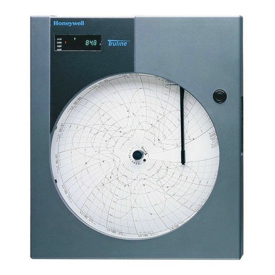
Honeywell DR4500A Product Manual
Classic series circular chart
recorder with or without control
Hide thumbs
Also See for DR4500A:
- Kit instructions (5 pages) ,
- Quick start manual (2 pages) ,
- Kit instruction (8 pages)

Related Manuals for Honeywell DR4500A


Summary of Contents for Honeywell DR4500A
- Page 1 DR4500A Classic Series Circular Chart Recorder With or Without Control Product Manual Doc. No.: 44-45-25-35 Release: Last Revision Date: April 2017 Honeywell Field Solutions...
- Page 2 Release M – April 2017 WARRANTY/REMEDY Honeywell warrants goods of its manufacture as being free of defective materials and faulty workmanship. Contact your local sales office for warranty information. If warranted goods are returned to Honeywell during the period of coverage, Honeywell will repair or replace without charge those items it finds defective.
- Page 3 51-52-05-01 Noise Environments Modbus® RTU Serial Communications User Manual 51-52-25-66 Modbus® RTU Serial Communications user Manual 51-52-25-69 Configuration Interface for DR4500 Supplement to 51-52-25-66 Release M DR4500A Classic Series Circular Chart Recorder With or Without Control Product Manual April 2017...
- Page 4 Area Organization Phone Number United States and 1-800-343-0228 Customer Service Honeywell Inc. Canada 1-800-423-9883 Global Technical Support Global Email Honeywell Process Solutions [email protected] Support DR4500A Classic Series Circular Chart Recorder With or Without Control Product Manual Release M April 2017...
-
Page 5: Symbol Definitions
Chassis Ground. Identifies a connection to the chassis or frame of the equipment shall be bonded to Protective Earth at the source of supply in accordance with national and local electrical code requirements. Release M DR4500A Classic Series Circular Chart Recorder With or Without Control Product Manual April 2017... -
Page 6: Table Of Contents
Timer Set Up Group ..................71 3.14 Alarms Set Up Group ..................72 3.15 Auxiliary Output Set Up Group ................ 74 3.16 Modbus Communications Set Up Group ............75 DR4500A Classic Series Circular Chart Recorder With or Without Control Product Manual Release M April 2017... - Page 7 Resetting and Displaying Totalizer Value ............. 144 5.14 Monitoring the External Event Operation ............146 5.15 Maximizing Pen Life ..................146 5.16 Routine Maintenance ..................147 Release M DR4500A Classic Series Circular Chart Recorder With or Without Control Product Manual April 2017...
- Page 8 Overview ......................202 Troubleshooting Aids ..................204 Self Diagnostics ..................... 206 Visual Failure Symptoms ................212 Troubleshooting Procedures ................. 213 Pen Alignment ....................219 viii DR4500A Classic Series Circular Chart Recorder With or Without Control Product Manual Release M April 2017...
- Page 9 GE2I-6057 ........................ 240 GR2I-6057 ........................ 241 IT2I-6057 ........................242 NO2I-6057 ........................ 243 PO2I-6057 ........................ 244 SP2I-6057 ......................... 245 SW2I-6057 ........................ 246 Index ....................247 Release M DR4500A Classic Series Circular Chart Recorder With or Without Control Product Manual April 2017...
- Page 10 Table 2-2 Procedure to access components ....................... 14 Table 2-3 Mounting flush in a new panel cutout ....................... 18 Table 2-4 Reference data for mounting DR4500A in existing panel cutouts ............19 Table 2-5 Mounting flush in a panel using universal filler kit ................... 20 Table 2-6 Mounting flush in a panel using Kent Model 105M cutout ...............
- Page 11 Table 8-1 Set up wiring procedure current proportional output/Aux Out 2 and 3 ........... 195 Table 8-2 Current proportional output/Aux Out 2 and 3 calibration procedure ............196 Release M DR4500A Classic Series Circular Chart Recorder With or Without Control Product Manual April 2017...
- Page 12 Table 10-3 Basic recorder parts without options ..................... 227 Table 10-4 Recorder parts associated with options ....................229 Table 10-5 Miscellaneous hardware kit ........................230 DR4500A Classic Series Circular Chart Recorder With or Without Control Product Manual Release M April 2017...
- Page 13 Figure 10-4 Recorder components associated with options ..................228 Figure 10-5 Internal cabling for DR4500A Classic recorder ................... 232 Figure 10-6 Internal diagram for DR4500A Classic recorder – options only ............233 Release M DR4500A Classic Series Circular Chart Recorder With or Without Control Product Manual...
- Page 14 DR4500A Classic Series Circular Chart Recorder With or Without Control Product Manual Release M April 2017...
-
Page 15: Overview
1.1 Introduction Function The DR4500A Classic Series recorder combines the simplicity of pen drawn analog traces with the sophistication of microprocessor controlled functions. This combination results in a user configurable recorder that is easily adapted to meet a variety of application requirements—from blast furnace to laboratory. - Page 16 Introduction Digital controller The DR4500A recorder includes an integral microprocessor-based, PID controller with two loops of control. A variety of output types, including a duplex variation for heat cool applications, lets you select the output that is right for your final control element.
-
Page 17: Operator Interface
Configuration mode - Displays function deviation, the green bar plus all ten small group and parameters. green bars will light. Figure 1-1 Operator interface Release M DR4500A Classic Series Circular Chart Recorder With or Without Control Product Manual April 2017... -
Page 18: Table 1-1 Function Of Keys
Decreases the setpoint, output, or configuration values displayed. Used to step through the items in each function while in configuration mode plus adjust control variables in the lower display. DR4500A Classic Series Circular Chart Recorder With or Without Control Product Manual Release M April 2017... -
Page 19: Set-Up Tasks
1.3 Set-up Tasks Major set-up tasks As shown in Figure 1-2, there are four major tasks that you must complete to "Set Up" the DR4500A recorder for operation. For easy reference the section numbers for each task are shown. START... - Page 20 Overview Set-up Tasks DR4500A Classic Series Circular Chart Recorder With or Without Control Product Manual Release M April 2017...
-
Page 21: Installation
2. Installation 2.1 Overview Introduction Installation of the DR4500A Recorder consists of mounting and wiring the recorder according to the instructions given in this section. Read the preinstallation information, check the model number interpretation and become familiar with your model selections, then proceed with installation. -
Page 22: Table 2-1 Operating Limits And Condensed Specifications
Green (large) = On Control Green (small) = Deviation to ±10% of PV Controller Modes of Manual Operation Operation Automatic with local setpoint Automatic with remote setpoint DR4500A Classic Series Circular Chart Recorder With or Without Control Product Manual Release M April 2017... - Page 23 Current Output 2 if Control "OUTALG" is not set to "CURRENT". Resolution: 12 bits over 0 to 21 mA Accuracy: 0.2% of full scale Temperature Stability: 0.03% F.S./°C Release M DR4500A Classic Series Circular Chart Recorder With or Without Control Product Manual April 2017...
- Page 24 0.10 Platinum –300 to 900 –184 to 482 100 ohms 0.40 0.22 0.05 –300 to 900 –184 to 482 500 ohms 0.20 0.11 0.05 DR4500A Classic Series Circular Chart Recorder With or Without Control Product Manual Release M April 2017...
- Page 25 +20 Vdc source for external dry contact or isolated solid state contacts. Selects one configured input. Totalizers One or two totalizers depending on model. Eight digit “totals” with multiplier on digital display. Release M DR4500A Classic Series Circular Chart Recorder With or Without Control Product Manual April 2017...
- Page 26 –103°F (–75°C). Accuracy stated is for Classic Series Recorder only, and does not include remaining system accuracies. DR4500A Classic Series Circular Chart Recorder With or Without Control Product Manual Release M April 2017...
-
Page 27: Model Number Interpretation
NOTE 1: = Totalization , Input 1 Every DR4500A recorder has all the available inputactuations stored in its nonvolatile memory = Math Only and can accept up to 4 inputs which must be specified sequentially in 1–4 entries in Table 1. -
Page 28: Table 2-2 Procedure To Access Components
Loosen the captive screw on the right hand side of the chart plate and swing the chart plate out. Reverse the steps to close the chart plate and door. DR4500A Classic Series Circular Chart Recorder With or Without Control Product Manual Release M April 2017... -
Page 29: Figure 2-2 Dr4500A Recorder Hardware Components Versus "Table" Selections
*Table I - XX00 X = 0,1, or 3 * Refer to Model Selection Guide 22077 Figure 2-2 DR4500A recorder hardware components versus “table” selections Release M DR4500A Classic Series Circular Chart Recorder With or Without Control Product Manual April 2017... -
Page 30: Mounting Considerations And Overall Dimensions
17.25 12.6 15.25 11.0 Front vie w Back vie w NEMA4X Figure 2-3 Overall dimensions DR4500A Classic Series Circular Chart Recorder With or Without Control Product Manual Release M April 2017... -
Page 31: Mounting Methods
The knockouts are really plugs that you just have to push out to remove. Side View Bottom View 2 1 4 0 5 Figure 2-4 How to remove knockouts Release M DR4500A Classic Series Circular Chart Recorder With or Without Control Product Manual April 2017... -
Page 32: Table 2-3 Mounting Flush In A New Panel Cutout
Hex screw, 1/4-20 x 1/2 inch and washer 2 1 4 0 6 Figure 2-5 Mounting Flush in a New Panel Cutout DR4500A Classic Series Circular Chart Recorder With or Without Control Product Manual Release M April 2017... -
Page 33: Table 2-4 Reference Data For Mounting Dr4500A In Existing Panel Cutouts
**Use procedure for “Cutout made for Kent Model 105M” Adapter plate dimensions The dimensions of the adapter plate (part number 30755134) are 16.5” x 19”. Release M DR4500A Classic Series Circular Chart Recorder With or Without Control Product Manual April 2017... -
Page 34: Table 2-5 Mounting Flush In A Panel Using Universal Filler Kit
21407 Support brackets Mounting brackets (supplied (included in kit 30755134-xxx with recorder) Figure 2-6 Mounting in a panel using universal filler kit DR4500A Classic Series Circular Chart Recorder With or Without Control Product Manual Release M April 2017... -
Page 35: Table 2-6 Mounting Flush In A Panel Using Kent Model 105M Cutout
2 " 7 " Drill two 1/4-inch holes 3-1/2" 2 1 4 0 8 Figure 2-7 Mounting in a panel using Kent Model 105M cutout Release M DR4500A Classic Series Circular Chart Recorder With or Without Control Product Manual April 2017... -
Page 36: Table 2-7 Procedure For Mounting Recorder With Nema4X Door
When completed all twenty screws should have a 5 to 8 lb-in of torque applied. This assures that the case and panel gaskets are adequately sealed against the panel. DR4500A Classic Series Circular Chart Recorder With or Without Control Product Manual Release M... -
Page 37: Figure 2-8 Panel Mounting Recorder With Nema4X Door
1/4-20 x 5/8 inch NOTE: Mounting brackets, attaching hardware, and panel gasket are included in kit 30755065-503 Figure 2-8 Panel Mounting Recorder with NEMA4X Door Release M DR4500A Classic Series Circular Chart Recorder With or Without Control Product Manual April 2017... -
Page 38: Table 2-8 Pipe Mounting Procedure
Install the U-bolts around the pipe and through the bracket holes. Secure with lockwashers and hex nuts provided. Pipe Mounting Washer Bracket Plastite Hex Nut Screw Rear Case U-bolt 24224 Figure 2-9 Pipe Mounting Brackets DR4500A Classic Series Circular Chart Recorder With or Without Control Product Manual Release M April 2017... -
Page 39: Table 2-9 Mounting Flush On A Surface (Of Panel Or Wall)
Hang the recorder on the screw by the support hook and insert the other two user-supplied screws through the brackets into the panel. Tighten the two hex screws that attach the brackets to the case. Release M DR4500A Classic Series Circular Chart Recorder With or Without Control Product Manual April 2017... -
Page 40: Figure 2-10 Mounting Flush On A Surface (Of Panel Or Wall)
196.22 7.725 181.36 163.32 6.430 7.14 18.03 0.710 2 1 4 0 9 Figure 2-10 Mounting flush on a surface (of panel or wall) DR4500A Classic Series Circular Chart Recorder With or Without Control Product Manual Release M April 2017... -
Page 41: Wiring Prerequisites
0.0047 μF capacitor. See each of the individual wiring diagrams. Release M DR4500A Classic Series Circular Chart Recorder With or Without Control Product Manual April 2017... -
Page 42: Table 2-10 Permissible Wiring Bundling
To determine the appropriate diagrams for wiring your recorder, refer to the model number interpretation in this section. The model number of the recorder can be found on the chart plate. DR4500A Classic Series Circular Chart Recorder With or Without Control Product Manual Release M... -
Page 43: Input Wiring Procedures
.0047µF Capacitor at the other end of the cable. An example of shield wiring to an external ground bus bar is shown in Figure 2-11. Release M DR4500A Classic Series Circular Chart Recorder With or Without Control Product Manual April 2017... -
Page 44: Figure 2-11 Ferrite Filter Locations And Shield Wiring (Ce Mark)
(North America), quick-acting, high breaking capacity, Type F, (Europe) 1/2 A, 250 V fuse(s) or circuit-breaker as part of the installation. The switch or DR4500A Classic Series Circular Chart Recorder With or Without Control Product Manual Release M... -
Page 45: Table 2-11 Ac Line Power Wiring
Input line voltage will be present on the instrument ground plane if safety ground is not attached; personal injury and product damage could result. Release M DR4500A Classic Series Circular Chart Recorder With or Without Control Product Manual April 2017... -
Page 46: Figure 2-12 Ac Line Power Wiring
Installation - Input Wiring Procedures Figure 2-12 AC line power wiring DR4500A Classic Series Circular Chart Recorder With or Without Control Product Manual Release M April 2017... -
Page 47: Table 2-12 Thermocouple, Rtd, Radiamatic, Mv, Or 0-5 Vdc Input Wiring
2-13 for specific input actuation plug wiring. Tighten the screws to secure the wires. Insert the wired plug into J2. Repeat steps 2 through 11 for input 2 printed circuit board as applicable. Release M DR4500A Classic Series Circular Chart Recorder With or Without Control Product Manual April 2017... -
Page 48: Figure 2-13 Thermocouple, Rtd, Radiamatic, Mv, Or 0-5 Vdc Input Wiring
Installation - Input Wiring Procedures Figure 2-13 Thermocouple, RTD, Radiamatic, mV, or 0–5 Vdc input wiring DR4500A Classic Series Circular Chart Recorder With or Without Control Product Manual Release M April 2017... -
Page 49: Table 2-13 4-20 Ma Input Wiring
J2. Tighten the screws in the plugs to secure the wires. Insert the wired plug into J2 and J11 as applicable. Repeat steps 2 through 11 for input 2 printed circuit board as applicable. Release M DR4500A Classic Series Circular Chart Recorder With or Without Control Product Manual April 2017... -
Page 50: Figure 2-14 4-20 Ma Input Wiring
Installation - Input Wiring Procedures Figure 2-14 4-20 mA input wiring DR4500A Classic Series Circular Chart Recorder With or Without Control Product Manual Release M April 2017... -
Page 51: Table 2-14 0-10 Volt Dc Input Wiring
Locate jumper position MA/W1 and make sure the jumper is in the W1 position. (See Figure 2-15 for the location.) Repeat steps 2 through 11 for input 2 printed circuit board as applicable. Release M DR4500A Classic Series Circular Chart Recorder With or Without Control Product Manual April 2017... -
Page 52: Figure 2-15 0-10 Volt Dc Input Wiring
Installation - Input Wiring Procedures Figure 2-15 0-10 Volt dc input wiring DR4500A Classic Series Circular Chart Recorder With or Without Control Product Manual Release M April 2017... -
Page 53: Output Wiring Procedures
Be sure that the 4-20 mA current output is aligned. Refer to subsection 8.2 Current Proportional Output Calibration. The 4-20 mA output can be used as a retransmission output if it is not used as a control output. Release M DR4500A Classic Series Circular Chart Recorder With or Without Control Product Manual April 2017... -
Page 54: Figure 2-16 4-20 Ma Control Output Wiring (Or Aux Out #2 And #3 Wiring)
Capacitor Capacitor Kit 51197755-001 Install capacitors as shown in figure. Figure 2-16 4-20 mA control output wiring (or Aux Out #2 and #3 wiring) DR4500A Classic Series Circular Chart Recorder With or Without Control Product Manual Release M April 2017... -
Page 55: Table 2-16 Position Proportional Control Output Wiring
Install the wired plug into J2 and J5, as applicable. Repeat steps 2 through 11 for Control Output #2 printed circuit board as applicable. Release M DR4500A Classic Series Circular Chart Recorder With or Without Control Product Manual April 2017... -
Page 56: Figure 2-17 Position Proportional Control Output Wiring
Relay 2 supply Capacitor Kit 51197755-001 Install capacitors as shown in figure. .0047 µF Plug J5 Capacitor Figure 2-17 Position proportional control output wiring DR4500A Classic Series Circular Chart Recorder With or Without Control Product Manual Release M April 2017... -
Page 57: Table 2-17 Relay Control Output Wiring
(refer to Figure 2-18); tighten the screws to secure the wires. Install the wired plug into J5. Repeat steps 2 through 10 for control output #2 printed circuit board as applicable. Release M DR4500A Classic Series Circular Chart Recorder With or Without Control Product Manual April 2017... -
Page 58: Figure 2-18 Relay Control Output Wiring
(for example: 115 Vac) must equal a number less Load calculation example: Resistance of customer than 5 amps controlled device Figure 2-18 Relay control output wiring DR4500A Classic Series Circular Chart Recorder With or Without Control Product Manual Release M April 2017... -
Page 59: Option Wiring Procedures
Figure 2-19 for the desired relay control action. The recorder is shipped with the W1 and W3 in N.C. positions. Install the wired plug into J4. Release M DR4500A Classic Series Circular Chart Recorder With or Without Control Product Manual April 2017... -
Page 60: Figure 2-19 Alarm Output Or Digital Input Wiring
Installation - Option Wiring Procedures Figure 2-19 Alarm output or digital input wiring DR4500A Classic Series Circular Chart Recorder With or Without Control Product Manual Release M April 2017... -
Page 61: Table 2-19 Alarm 3 And Alarm 4 Output Wiring
Insert the wires for the alarm devices into the appropriate screw clamps as shown. Refer to Figure 2-20. Tighten the screws to secure the wires. Install the wired plug into J5. Release M DR4500A Classic Series Circular Chart Recorder With or Without Control Product Manual April 2017... -
Page 62: Table 2-20 Alarm 5 And Alarm 6 Output Wiring
Insert the wires for the alarm devices into the appropriate screw clamps as shown. Refer to Figure 2-20. Tighten the screws to secure the wires. Install the wired plug into J5. DR4500A Classic Series Circular Chart Recorder With or Without Control Product Manual Release M April 2017... -
Page 63: Figure 2-20 Alarm Outputs #3, 4, 5, And 6 Wiring
Relay Load W4 = N.O. contact W5 = N.C. contact .0047 μF Ferrite filter Capacitor Figure 2-20 Alarm outputs #3, 4, 5, and 6 wiring Release M DR4500A Classic Series Circular Chart Recorder With or Without Control Product Manual April 2017... -
Page 64: Table 2-21 Rs485 Modbus Communications Wiring
Install the wired plug J3 into J3 connector on the communications board. REFERENCE Refer to Documents 51-52-25-66 and 51-52-25-69 for a complete description of RS485 Modbus Communications Option. DR4500A Classic Series Circular Chart Recorder With or Without Control Product Manual Release M April 2017... -
Page 65: Figure 2-21 Rs485 Modbus Communications Wiring
Installation - Option Wiring Procedures Figure 2-21 RS485 Modbus communications wiring Release M DR4500A Classic Series Circular Chart Recorder With or Without Control Product Manual April 2017... -
Page 66: Table 2-22 4-20 Ma Auxiliary Output Wiring
Auxiliary output 2 and Auxiliary output 3 use Control current output 1 and Control current output 2 if Control “OUT ALG” is not set to “CURRENT”. DR4500A Classic Series Circular Chart Recorder With or Without Control Product Manual Release M... -
Page 67: Figure 2-22 4-20 Ma Auxiliary Output Wiring
.0047 µF Capacitor Figure 2-22 4-20 mA auxiliary output wiring ATTENTION Refer to Figure 2-16 for Auxiliary Output 2 and Auxiliary Output 3 wiring. Release M DR4500A Classic Series Circular Chart Recorder With or Without Control Product Manual April 2017... -
Page 68: Lockout Switch Configuration
Lockout can also be configured under set up group “LOCKOUT”. See Subsection 3.18. This feature also includes the special screw and plate that provide the lead seal capability for sealing the chart plate. DR4500A Classic Series Circular Chart Recorder With or Without Control Product Manual Release M April 2017... -
Page 69: Configuration
These prompts let you know what group of configuration data (set up prompts) you are working with and also the specific parameters (function prompts) associated with each group. Figure 3-1 shows an overview of the prompt hierarchy. Release L DR4500A Classic Series Circular Chart Recorder With or Without Control Product Manual February 2017... -
Page 70: Configuration Prompts
Configuration Configuration Prompts 3.2 Configuration Prompts Diagram: prompt hierarchy Figure 3-1 shows an overview of the DR4500A Set Up prompts and their associated Function prompt - read from left to right. Figure 3-1 DR4500A prompt hierarchy Set Up Group Function Prompts... - Page 71 For field calibration—see Calibration section of manual CALIB VERSION FAILSAFE* RAM TEST CONFTEST CAL TEST FACT CRC BATTERY STATUS *Displayed on test failure only Release M DR4500A Classic Series Circular Chart Recorder With or Without Control Product Manual April 2017...
-
Page 72: How To Get Started
Set up the recorder in this order: Inputs (Display will be correct) Pens Chart Alarms Control Tuning Other functions as needed DR4500A Classic Series Circular Chart Recorder With or Without Control Product Manual Release M April 2017... -
Page 73: Configuration Tips
not in Set Up mode, press SET UP key first key malfunction, do keyboard test (operation) individual key locked out Release M DR4500A Classic Series Circular Chart Recorder With or Without Control Product Manual April 2017... -
Page 74: Configuration Procedure
Set Up group you have selected. Stop at the function prompt that you want to change, then proceed to the next step. DR4500A Classic Series Circular Chart Recorder With or Without Control Product Manual Release M April 2017... - Page 75 This exits configuration mode and returns the recorder to DISP the same state it was in immediately preceding entry into the Set Up mode. It stores any changes you have made. Release M DR4500A Classic Series Circular Chart Recorder With or Without Control Product Manual April 2017...
-
Page 76: Input Set Up Group
K TC L 4-20 mA NNM TC 0-10 mV NIC TC 10-50m R TC 0-5 V S TC 0-10 V T TC H RADIAM DR4500A Classic Series Circular Chart Recorder With or Without Control Product Manual Release M April 2017... - Page 77 FILTER 1 Input 1 Filter 0 to 120 seconds BURNOUT Burnout Protection NONE DOWN EMISSIV Emissivity .01 to 1.00 Repeat this procedure for INPUT 2. Release M DR4500A Classic Series Circular Chart Recorder With or Without Control Product Manual April 2017...
-
Page 78: Pen Set Up Group
Pen Chart Position for ON 0 to 100% 91.0 Event PEN1OFF Pen Chart Position for OFF 0 to 100% 93.0 Event Repeat this procedure for PEN 2. DR4500A Classic Series Circular Chart Recorder With or Without Control Product Manual Release M April 2017... -
Page 79: Chart Set Up Group
7DAYS XHR (See prompt "HOUR/REV") HOUR/REV Hours per Revolution 1 to 744 (appears only if "XHR" is selected above) –– LINEARIZ Linearization LINEAR NONLIN Release M DR4500A Classic Series Circular Chart Recorder With or Without Control Product Manual April 2017... -
Page 80: Totalizer Set Up Group
*Total will be set to “0” on closure of the assigned external switch. INHIBIT Totalizer Inhibit NONE NONE S1 OPEN S1 CLOSE S2 OPEN S2 CLOSE Repeat this procedure for INPUT 2. DR4500A Classic Series Circular Chart Recorder With or Without Control Product Manual Release M April 2017... -
Page 81: Control Set Up Group
–5.0 to 105.0% of output OUTHILIM High Output Limit 100.0 –5.0 to 105.0% of output OUTLOLIM Low Output Limit –5.0 to 105.0% of output DROPOFF Controller Dropoff Value Release M DR4500A Classic Series Circular Chart Recorder With or Without Control Product Manual April 2017... - Page 82 *Note: GAIN must be used with OUTPUT ALG settings of TIME D (TIME DUPLEX) or TI CUR (TIME CURRENT) Repeat this procedure for CONTROL 2. DR4500A Classic Series Circular Chart Recorder With or Without Control Product Manual Release M April 2017...
-
Page 83: Tuning Parameters Set Up Group
CYC SEC Cycle Time (Heat) 1 to 120 seconds 20.0 Electromechanical Relays CYC2 SEC Cycle Time 2 (Cool) 1 to 120 seconds 20.0 Electromechanical Relays Release M DR4500A Classic Series Circular Chart Recorder With or Without Control Product Manual April 2017... -
Page 84: Sp Ramp Set Up Groups
SP PROG* Setpoint Programming DISABL DISABL (Refer to Section 6) ENABLE *Only one of these can be enabled at a time. DR4500A Classic Series Circular Chart Recorder With or Without Control Product Manual Release M April 2017... -
Page 85: Timer Set Up Group
ALARM1 REPEAT ON-TIME Timer Repeat Mode 1 SEC On-Time 2 SEC 3 SEC 4 SEC 5 SEC INCRMENT Timer Count Increment MINUTE MINUTE SECOND Release M DR4500A Classic Series Circular Chart Recorder With or Without Control Product Manual April 2017... -
Page 86: Alarms Set Up Group
Controller 2 output algorithms Relay Simplex, Position Proportional, Relay Duplex, Current/Relay Duplex Alarm 5 Controller 2 output algorithms Position Proportional, Relay Duplex, Current/Relay Duplex Alarm 6 DR4500A Classic Series Circular Chart Recorder With or Without Control Product Manual Release M April 2017... -
Page 87: Table 3-12 Alarms Group Function Prompts
Alarm Hysteresis 0.0 to 100.0 % of Input Span as appropriate Repeat this procedure for ALARM 2, ALARM 3, ALARM 4, ALARM 5, ALARM 6. Release M DR4500A Classic Series Circular Chart Recorder With or Without Control Product Manual April 2017... -
Page 88: Auxiliary Output Set Up Group
20mA VAL High Scaling Factor High scale value to represent 20 mA 100.0 Repeat this procedure for AUX OUT 2 and AUX OUT 3. DR4500A Classic Series Circular Chart Recorder With or Without Control Product Manual Release M April 2017... -
Page 89: Modbus Communications Set Up Group
NONE NONE (in milliseconds) 10MSEC 20MSEC 30MSEC 40MSEC 50MSEC DBL BYTE Double Byte Order FP B FP B FP BB FP L FP LB Release M DR4500A Classic Series Circular Chart Recorder With or Without Control Product Manual April 2017... -
Page 90: Options Set Up Group
–999.0 to 9999 DEVSETPT Deviation Setpoint Value SCROLL Lower Display Scroll NONE NONE 1 SEC 2 SEC 3 SEC GRANDTOT Grand Totalizer ENABLE DISABL DISABL DR4500A Classic Series Circular Chart Recorder With or Without Control Product Manual Release M April 2017... -
Page 91: Lockout Set Up Group
This feature also includes the special screw and plate that provide for the lead seal capability for sealing the chart plate. Release M DR4500A Classic Series Circular Chart Recorder With or Without Control Product Manual April 2017... -
Page 92: Configuration Record Sheet
_______ (Value) _______ E0 GAL RSET TOT _______ TOTAL 1 _______ DISABL TOTAL EU _______ RATE _______ SECOND SCALER _______ RSETABLE _______ INHIBIT NONE DR4500A Classic Series Circular Chart Recorder With or Without Control Product Manual Release M April 2017... - Page 93 RAMPUNIT _______ — SYNC 1+2 _______ — SPP SEGS SEGxRAMP _______ — SEGx SP _______ — SEGxTIME _______ — SPP EVNT SEGx EV _______ Release M DR4500A Classic Series Circular Chart Recorder With or Without Control Product Manual April 2017...
- Page 94 A4S1SCAL _______ DEVSETPT _______ NONE A4S2 H L _______ SCROLL _______ DISABL A4S2SCAL _______ GRANDTOT _______ AL4 HYST _______ CALIB LOCKOUT LOCKOUT _______ XXXX DR4500A Classic Series Circular Chart Recorder With or Without Control Product Manual Release M April 2017...
-
Page 95: Configuration Parameter Definitions
Alarms Set Up Group 4.11 Auxiliary Output Set Up Group 4.12 Modbus Communications Set Up Group 4.13 Options Set Up Group 4.14 Lockout Parameters Set Up Group Release M DR4500A Classic Series Circular Chart Recorder With or Without Control Product Manual April 2017... -
Page 96: Input Parameters Set Up Group
(blank) left to right, with highlighting (increased brightness) of each digit. The value of each digit can be changed only when it is highlighted. DR4500A Classic Series Circular Chart Recorder With or Without Control Product Manual Release M April 2017... - Page 97 These selections appear only with XMITTER prompt, which appears only if a linear type is configured input type. Go to prompt “XMITTER” to characterize the input. Release M DR4500A Classic Series Circular Chart Recorder With or Without Control Product Manual April 2017...
- Page 98 High Range display value = 250 Then 20 mA = 250 Gal/Min The control setpoint will be limited by the range of units selected here. DR4500A Classic Series Circular Chart Recorder With or Without Control Product Manual Release M April 2017...
- Page 99 Available only for “Radiamatic” inputs. Repeat the procedure for INPUT 2 configuration. Release M DR4500A Classic Series Circular Chart Recorder With or Without Control Product Manual April 2017...
-
Page 100: Pen Parameters Set Up Group
(n = 1 or 2) pen 1 (pen 2). CHART HI minus CHART LO equals Chart Range (must be whole number = 2 or greater). DR4500A Classic Series Circular Chart Recorder With or Without Control Product Manual Release M April 2017... - Page 101 (trace) occurrence of an OFF event. Prompt only appears if DGTL1 or 2 is selected as pen 1 (pen 2) input. Repeat this procedure for PEN 2 configuration. Release M DR4500A Classic Series Circular Chart Recorder With or Without Control Product Manual April 2017...
-
Page 102: Chart Parameters Set Up Group
HOURS PER REVOLUTION — Set the desired chart HOUR/REV 1 to 744 Hours speed. Appears only if XHR was selected at prompt “CHRT SPD”. LINEARIZ LINEARIZATION LINEAR NONLIN DR4500A Classic Series Circular Chart Recorder With or Without Control Product Manual Release M April 2017... -
Page 103: Total Parameters Set Up Group
(increased brightness) of (blank) each digit. The value of each digit can be changed only when it is highlighted. Release M DR4500A Classic Series Circular Chart Recorder With or Without Control Product Manual April 2017... - Page 104 External SW1 closed inhibits totalizer. S2 OPEN External SW2 open inhibits totalizer. S2 CLOSE External SW2 closed inhibits totalizer. Repeat the configuration for TOTAL 2. DR4500A Classic Series Circular Chart Recorder With or Without Control Product Manual Release M April 2017...
-
Page 105: Control Parameters Set Up Group
4.6 Control Parameters Set Up Group Introduction The functions listed in this group deal with how the DR4500A will control the process including: number of tuning parameter sets, setpoint source, ratio, bias, tracking, power-up recall, setpoint limits, output direction and limits, deadband and hysteresis, control algorithm, output algorithm, and the current duplex range. - Page 106 It establishes the correct relationship between the remote setpoint and the input 2 signal applied according to the formula below (under Bias). Input 2 must be enabled. DR4500A Classic Series Circular Chart Recorder With or Without Control Product Manual Release M April 2017...
- Page 107 The setting must be equal to or less than the upper range of input 1 and input 2. Input 2, when configured for remote setpoint, will be restricted to this upper limit. Release M DR4500A Classic Series Circular Chart Recorder With or Without Control Product Manual April 2017...
- Page 108 *The Local Setpoint will automatically adjust itself to be within the setpoint limit range. For example, if SP = 1500 and the SP HILIM is changed to 1200, the new Local Setpoint will be 1200. DR4500A Classic Series Circular Chart Recorder With or Without Control Product Manual Release M...
- Page 109 GAIN selects the unitless term of gain for the P term of the PID algorithm, where: (must be used with settings of TIME D (TIME DUPLEX) or TI GAIN =100%FS CUR (TIME CURRENT) Release M DR4500A Classic Series Circular Chart Recorder With or Without Control Product Manual April 2017...
- Page 110 Both Deadband and Hysteresis are separately adjustable. With no relay action the controller will read 50%. Other prompts affected: “OUT HYST” and “DEADBAND” DR4500A Classic Series Circular Chart Recorder With or Without Control Product Manual Release M April 2017...
- Page 111 PD (Two Mode) control, P (Single Mode) control. Set Rate (D) and/or Reset Time (I) to 0. Other prompts affected: "MAN RSET" Release M DR4500A Classic Series Circular Chart Recorder With or Without Control Product Manual April 2017...
- Page 112 Controller #1 uses Relay 3 and overrides control of relay by Alarm 3. Controller #2 uses Relay 5 and overrides control of relay by Alarm 5. DR4500A Classic Series Circular Chart Recorder With or Without Control Product Manual Release M April 2017...
- Page 113 0-100% output change and the relay output to provide cool control. Repeat this procedure for CONTROL 2 configuration. Release M DR4500A Classic Series Circular Chart Recorder With or Without Control Product Manual April 2017...
-
Page 114: Tuning Parameters Set Up Group
TuneON. New PID parameters will be entered automatically when tuning is complete. AT ERR NONE ACCUTUNE ERROR CODES (Read Only) IDFL ABRT DR4500A Classic Series Circular Chart Recorder With or Without Control Product Manual Release M April 2017... - Page 115 (offset) from setpoint. This eliminates the offset and lets the PV line out at setpoint. Release M DR4500A Classic Series Circular Chart Recorder With or Without Control Product Manual April 2017...
- Page 116 Duplex models as the cycle time in the "COOL" zone of Heat/Cool applications or for second set of PID constants. Electromechanical relays DR4500A Classic Series Circular Chart Recorder With or Without Control Product Manual Release M April 2017...
-
Page 117: Setpoint Ramp Set Up Group
ENABLE ENABLE SETPOINT RAMP — Allows you to start the setpoint ramp (in automatic mode). DISABLE SETPOINT RAMP — Disables the setpoint DISABL ramp. Release M DR4500A Classic Series Circular Chart Recorder With or Without Control Product Manual April 2017... - Page 118 For reasons of convenience, the information for the DISABL prompts when SP PROG is enabled are included in Section 6 Setpoint Ramp/Soak Programming Option. DR4500A Classic Series Circular Chart Recorder With or Without Control Product Manual Release M April 2017...
-
Page 119: Timer Set Up Group
Relay 1 on-time when timer is in repeat mode. 2 SEC 3 SEC 4 SEC 5 SEC INCRMENT MINUTE Selects the units of the timer. SECOND Release M DR4500A Classic Series Circular Chart Recorder With or Without Control Product Manual April 2017... -
Page 120: Alarms Set Up Group
Controller 2 output algorithms Relay Simplex, Position Proportional, Relay Duplex, Current/Relay Duplex Alarm 5 Controller 2 output algorithms Position Proportional, Relay Duplex, Current/Relay Duplex Alarm 6 DR4500A Classic Series Circular Chart Recorder With or Without Control Product Manual Release M April 2017... -
Page 121: Table 4-10 Alarms Group Definitions
ALARM x SETPOINT 2 TYPE — select what you want AxS2TYPE Same as AxS1TYPE Setpoint 2 of Alarm x to represent. The selections are the same as AxS1TYPE. Release M DR4500A Classic Series Circular Chart Recorder With or Without Control Product Manual April 2017... - Page 122 OUTPUT signals as a % of the full scale output range. Repeat this procedure for Alarm 2, Alarm 3, Alarm 4, Alarm 5, Alarm 6 configuration. DR4500A Classic Series Circular Chart Recorder With or Without Control Product Manual Release M April 2017...
-
Page 123: Auxiliary Output Set Up Group
NOTE: A deviation of 0°F yields an auxiliary output of 50%. OUT 1 OUTPUT 1—Represents the displayed controller output in percent (%) for Loop 1. Release M DR4500A Classic Series Circular Chart Recorder With or Without Control Product Manual April 2017... - Page 124 Auxiliary Output High Value will produce a low end (4 mA) output. Repeat for AUX OUT 2 and AUX OUT 3. DR4500A Classic Series Circular Chart Recorder With or Without Control Product Manual Release M April 2017...
-
Page 125: Modbus Communications Set Up Group
4.12 Modbus Communications Set Up Group Introduction This option allows the DR4500A to be connected to a host computer via the Modbus protocol. Up to 99 addresses and a maximum of 15 units can be configured over this link. REFERENCE Refer to Documents 51-52-25-66 and 51-52-25-69 for a complete description of the RS485 Modbus Communications Option. -
Page 126: Options Set Up Group
DEVIATION SETPOINT VALUE – sets the desired –999.0 to 9999 DEVSETPT deviation setpoint value for deviation recording. This prompt only appears if “SETPNT” was selected at prompt “DEVIATION” previously. DR4500A Classic Series Circular Chart Recorder With or Without Control Product Manual Release M April 2017... -
Page 127: April
3 SEC GRANDTOT ENABLE GRAND TOTALIZER—When enabled it prints, on the DISABL chart, the sum of ALL the enabled totalizers as TOTAL = XXXXXXXXXXX. Release M DR4500A Classic Series Circular Chart Recorder With or Without Control Product Manual April 2017... -
Page 128: Lockout Parameters Set Up Group
All other groups are read only. Calibration group is not available. MAX – Calibration group not available. All other groups are Read-only. ATTENTION Do not leave in “NONE” Lockout. DR4500A Classic Series Circular Chart Recorder With or Without Control Product Manual Release M April 2017... -
Page 129: Operation
4 2 H 4 3 H 4 4 H 5 .16 R outine Maintenance 1 47 4 5 H 4 6 H 4 7 H Release K DR4500A Classic Series Circular Chart Recorder With or Without Control Product Manual May 2013... -
Page 130: Preparation
Operation - Preparation 5.2 Preparation Introduction After the DR4500A recorder is installed and configured, there are a few preparation tasks to perform prior to start-up. These tasks include: installing the chart, setting the time line, and changing the chart hub, if necessary. -
Page 131: Figure 5-1 Basic Recording Components
Removable chart hub Large chart hub adapter (pull Zero position off to expose smaller hub) of pen arm 22087 Figure 5-1 Basic recording components Release M DR4500A Classic Series Circular Chart Recorder With or Without Control Product Manual April 2017... -
Page 132: Start-Up
Note that the recorder is “awake” during start-up to verify interaction with the process. During start-up, you should verify the interaction between your process and the DR4500A recorder to be sure that your process can tolerate some upsets during this procedure. -
Page 133: Table 5-4 Procedure For Testing The Displays And Keys
If no key is pressed for 25 seconds, the test times out and the recorder exits the key test. If any test fails, go to subsection 9.3 Self Diagnostics for more information. Release M DR4500A Classic Series Circular Chart Recorder With or Without Control Product Manual April 2017... -
Page 134: Table 5-5 Procedure For Starting Up The Recorder
Refer to Set Up group TUNING 1 or TUNING 2 to ensure that the proper selections for PROP BD or GAIN, RATE MIN, and RSET MIN or RSET RPM have been entered. DR4500A Classic Series Circular Chart Recorder With or Without Control Product Manual Release M April 2017... -
Page 135: Monitoring Your Recorder
F igure 5-2 is a view of the operator interface. A description of the displays and indicators is included. 6 2 H Release M DR4500A Classic Series Circular Chart Recorder With or Without Control Product Manual April 2017... -
Page 136: Figure 5-2 Operator Interface
Configuration mode - Displays function deviation, the green bar plus all ten small group and parameters. green bars will light. Figure 5-2 Operator interface DR4500A Classic Series Circular Chart Recorder With or Without Control Product Manual Release M April 2017... -
Page 137: Table 5-6 Meaning Of Indicators
* ALM1 indicator can also mean the Interval Timer has timed out. Alarms 3-6 are indicated by a message on the lower display. See T able 5-9. 6 4 H Release M DR4500A Classic Series Circular Chart Recorder With or Without Control Product Manual April 2017... -
Page 138: Figure 5-3 Deviation Bargraph
+1 to +10% small green dev iation bars Green "on control" -1 to -10% small green dev iation bars 21424 Figure 5-3 Deviation bargraph DR4500A Classic Series Circular Chart Recorder With or Without Control Product Manual Release M April 2017... -
Page 139: Table 5-7 Lower Display Key Parameter Prompts
Time remaining in Timer function Time elapsed in Timer function TUNExXXX** Accutune II indicator. x = Loop number (1 or 2). XXX = ON or OFF. Release M DR4500A Classic Series Circular Chart Recorder With or Without Control Product Manual April 2017... -
Page 140: Table 5-8 Error Messages
Diagnostic error messages The DR4500A runs background tests to verify data and memory integrity. If there is a malfunction, an error message will blink in the lower display. In the case of more than one simultaneous malfunction or alarm, each message will be shown in succession. -
Page 141: Table 5-9 Alarm And Tuning Messages
An active alarm will always provide an indication on the display but may not control its associated relay; that is, a higher priority function such as a control loop or timer may have control of the relay. Release M DR4500A Classic Series Circular Chart Recorder With or Without Control Product Manual April 2017... -
Page 142: Operator Functions
Controller #1 and “2” means that the values apply for Controller #2. Sequentially press the LOWR DISP key to scroll through the displays and light the appropriate CHN indicator for controller-related values. DR4500A Classic Series Circular Chart Recorder With or Without Control Product Manual Release M... -
Page 143: Operating Modes
If RSP tracking is not configured, the local setpoint will not be altered when the transfer is made. See subsection 3.10 Control Set Up Group "SP TRACK". Selecting manual or automatic mode Release M DR4500A Classic Series Circular Chart Recorder With or Without Control Product Manual April 2017... -
Page 144: Table 5-12 Procedure For Selecting Automatic Or Manual Mode
Upper Display: shows the PV value Lower Display: shows OUT and the output value in % “A” indicator appears indicating automatic mode. Return to automatic mode AUTO DR4500A Classic Series Circular Chart Recorder With or Without Control Product Manual Release M April 2017... -
Page 145: Setpoints
Change the value Change the local setpoint to the value at which you want the process maintained. The deviation bargraph indicates PV deviation from setpoint. Release M DR4500A Classic Series Circular Chart Recorder With or Without Control Product Manual April 2017... -
Page 146: Table 5-15 Procedure For Switching Between Setpoints
Note 1—RSP blinks when RSP is reached using Digital Input. Note 2—RSP solid for 2nd Setpoint Note 3—RSP blinks for 2nd setpoint activated by Digital Input. DR4500A Classic Series Circular Chart Recorder With or Without Control Product Manual Release M April 2017... -
Page 147: Single Setpoint Ramp
Lower Display: FINAL SP ▲ ▼ Change the upper display value to the desired final setpoint value. Setting Range = within the setpoint limits Release M DR4500A Classic Series Circular Chart Recorder With or Without Control Product Manual April 2017... -
Page 148: Table 5-18 Procedure For Running A Setpoint Ramp
ATTENTION Any time the local setpoint is different from the final setpoint value and the RUN/HOLD key is pressed, the ramp will start again. DR4500A Classic Series Circular Chart Recorder With or Without Control Product Manual Release M April 2017... - Page 149 ▲ You will see: Upper Display: DISABL Lower Display: SP RAMP X LOWR Return to normal Returns to normal operating mode. operating mode DISP Release M DR4500A Classic Series Circular Chart Recorder With or Without Control Product Manual April 2017...
-
Page 150: Using Two Sets Of Tuning Constants (Pid Values)
If you select 2 PVSW or 2 SPSW, you must set a value at which the sets will switch over. The procedure in T able 5-20 shows you how to set this value. 7 8 H DR4500A Classic Series Circular Chart Recorder With or Without Control Product Manual Release M April 2017... -
Page 151: Table 5-20 Procedure For Setting Switchover Values
**PIDSET2 – will be used when PV or SP, whichever is selected, is less than the switchover value. ▲ ▼ Change the value of any of the above listed prompts in the lower display. Release M DR4500A Classic Series Circular Chart Recorder With or Without Control Product Manual April 2017... -
Page 152: Table 5-22 Procedure For Switching Pid Sets From The Keyboard
DISP display Upper Display: The PV value Lower Display: PIDSETX X = 1 or 2 ▲ ▼ Change PIDSET1 to PIDSET2 or vice versa. DR4500A Classic Series Circular Chart Recorder With or Without Control Product Manual Release M April 2017... -
Page 153: Using Accutune Ii
= 1 or 2 Tuning will begin and the lower display will flash “TUNING”. When tuning has been ompleted the lower display will again show “TUNExOFF”. Release M DR4500A Classic Series Circular Chart Recorder With or Without Control Product Manual April 2017... -
Page 154: Table 5-24 Procedure For Using Accutune For Duplex Control
When tuning has been completed the lower display will again show “TUNExOFF”. The Heat tuning parameters are entered for the first set of PID constants in the Tuning Set Up group. DR4500A Classic Series Circular Chart Recorder With or Without Control Product Manual Release M April 2017... - Page 155 “TUNExOFF”. The Cool tuning parameters are entered for the second set of PID constants in the Tuning Set Up group. Release M DR4500A Classic Series Circular Chart Recorder With or Without Control Product Manual April 2017...
-
Page 156: Alarm Setpoints
1, 2, 3, 4, 5, or 6 ▲ ▼ Change any alarm setpoint value you select in the upper display. Return to normal LOWR Returns to normal operation. operation DISP DR4500A Classic Series Circular Chart Recorder With or Without Control Product Manual Release M April 2017... -
Page 157: Digital Input Option (Remote Switching)
If a particular mode or parameter is selected by the contact closure, using the keyboard to select the same parameter ensures that the selected mode will be maintained after the remote digital switch is reopened. Release M DR4500A Classic Series Circular Chart Recorder With or Without Control Product Manual April 2017... -
Page 158: Resetting And Displaying Totalizer Value
The totalizer can be reset to “0” from external switch #1 or external switch #2. Refer to Subsection 3.9 – Totalizer Set Up Group and set function prompt “RSETABLE” to “EXT SW1” or “EXT SW2”. DR4500A Classic Series Circular Chart Recorder With or Without Control Product Manual Release M... -
Page 159: Table 5-28 Procedure For Displaying The Totalizer Value
#1, #2 PV values while lower display shows #1, #2 totalization values. Return to Normal PV LOWR Returns to normal PV display. Display DISP Release M DR4500A Classic Series Circular Chart Recorder With or Without Control Product Manual April 2017... -
Page 160: Monitoring The External Event Operation
Be sure the chart hub assembly is pushed onto the motor shaft so that it is flush with the chart plate. DR4500A Classic Series Circular Chart Recorder With or Without Control Product Manual Release M April 2017... -
Page 161: Routine Maintenance
Operation - Routine Maintenance 5.16 Routine Maintenance Introduction The DR4500A recorder does not require any periodic maintenance as such. But you will have to replace the ink cartridge, and replace the chart and optional chart lamp, as required. CAUTION Do not lubricate the plastic gears on the chart and pen motors. -
Page 162: Installing/Replacing Chart
In addition, you may want to air purge the case if the recorder is mounted in an extremely dusty environment. DR4500A Classic Series Circular Chart Recorder With or Without Control Product Manual Release M April 2017... -
Page 163: Setpoint Ramp/Soak Programming And Operation
The program is placed in hold at the beginning. The Manual/Auto mode will be as configured under “POWER UP” in the “CONTROL” group. Release K DR4500A Classic Series Circular Chart Recorder With or Without Control Product Manual May 2013... - Page 164 6.6 Setpoint Program Profiles Set Up Group 6.7 Setpoint Program Segments Set Up Group 6.8 Setpoint Program Event Set Up Group 6.9 Run/Monitor the Program DR4500A Classic Series Circular Chart Recorder With or Without Control Product Manual Release M April 2017...
-
Page 165: Setpoint Program Contents
This determines the status of the recorder upon completion of the profile. The selections are: LAST SP = hold at the last setpoint in the program F SAFE = Manual mode, Failsafe Output Release M DR4500A Classic Series Circular Chart Recorder With or Without Control Product Manual April 2017... - Page 166 Each segment can be programmed to trigger an alarm which in turn deenergizes the associated relay. The selected alarm must be programmed as an event type for this to occur. Selections are: ALARM 1 – ALARM 6. DR4500A Classic Series Circular Chart Recorder With or Without Control Product Manual Release M April 2017...
- Page 167 RN/HLD to support this function. The valid states of the contacts are: RUN—contact closure places program in HOLD state HOLD—contact open places program in RUN state Release M DR4500A Classic Series Circular Chart Recorder With or Without Control Product Manual April 2017...
-
Page 168: Drawing A Ramp/Soak Profile
SE G 1 SG 1 2 20 0 Ti me /Ho urs 0 11 12 13 14 15 16 20765 Figure 6-1 Ramp/Soak profile example DR4500A Classic Series Circular Chart Recorder With or Without Control Product Manual Release M April 2017... -
Page 169: Table 6-1 Parameter Settings For Example 12-Step Profile
3hr.:0min. Event ALARM1 Reminder: There are up to 36 segments available for inclusion in a profile. The above example uses only the first 12. Release M DR4500A Classic Series Circular Chart Recorder With or Without Control Product Manual April 2017... - Page 170 This will give you a permanent record of your program and will assist you when entering the ramp and soak values. Profile 1 20766 Profile 2 20766 DR4500A Classic Series Circular Chart Recorder With or Without Control Product Manual Release M April 2017...
- Page 171 Setpoint Ramp/Soak Programming and Operation - Drawing a Ramp/Soak Profile Profile 3 20766 Profile 4 20766 Release M DR4500A Classic Series Circular Chart Recorder With or Without Control Product Manual April 2017...
- Page 172 Setpoint Ramp/Soak Programming and Operation - Drawing a Ramp/Soak Profile Profile 5 20766 Profile 6 20766 DR4500A Classic Series Circular Chart Recorder With or Without Control Product Manual Release M April 2017...
-
Page 173: Entering The Setpoint Program Data
Using the FUNCTION key, follow the prompts shown in Sections 6.5, 6.6, and 6.7. Release M DR4500A Classic Series Circular Chart Recorder With or Without Control Product Manual April 2017... - Page 174 Repeat steps 4 and 5 for each function you want to change. LOWR Exit configuration This exits from the configuration mode. DISP DR4500A Classic Series Circular Chart Recorder With or Without Control Product Manual Release M April 2017...
-
Page 175: Sp Ramp1 And Sp Ramp2 Set Up Group
LSP. For FSAFE selection, the recorder is switched to manual mode and to the selected failsafe output value. Release M DR4500A Classic Series Circular Chart Recorder With or Without Control Product Manual April 2017... - Page 176 STATE Program State at end DISABL HOLD RECOVERY Program resumes after power ENABLE interruption DISABLE PROG END SP value after last segment LASTSP FSAFE DR4500A Classic Series Circular Chart Recorder With or Without Control Product Manual Release M April 2017...
-
Page 177: Setpoint Program Profiles Set Up Group
Both SP programs will RUN or HOLD simultaneously. A Guaranteed Soak Hold on one profile will cause the other profile to HOLD for the duration of the Guaranteed Soak Hold. Release M DR4500A Classic Series Circular Chart Recorder With or Without Control Product Manual April 2017... - Page 178 End Segment for Program 6 SOAK2 to SOAK36 RAMPUNIT Ramp Type TIME EU/MIN EU/HR SYNC 1+2 Synchronizes Profile for Control Loops ENABLE 1 and 2 DISABL DR4500A Classic Series Circular Chart Recorder With or Without Control Product Manual Release M April 2017...
-
Page 179: Setpoint Program Segments Set Up Group
The soak segment's setpoint value range limits in engineering units (x = 2, 4, 6…36) The soak segment’s duration. SEGxTIME 0-99 hrs:59 min. (x = 2, 4, 6…36) Release M DR4500A Classic Series Circular Chart Recorder With or Without Control Product Manual April 2017... - Page 180 Soak SP Within SP Soak Time 00.00 to 99.59 limits SG12TIME SG25RAMP Soak TIme 00.00 to 99.59 Ramp 00.00 to 99.59 or 0 to 999 DR4500A Classic Series Circular Chart Recorder With or Without Control Product Manual Release M April 2017...
- Page 181 00.00 to 99.59 limits or 0 to 999 SG30TIME SEG36SP Soak Time 00.00 to 99.59 Soak SP Within SP limits SG36TIME Soak Time 00.00 to 99.59 Release M DR4500A Classic Series Circular Chart Recorder With or Without Control Product Manual April 2017...
-
Page 182: Setpoint Program Event Set Up Group
Program A1S1TYPE or A1S2TYPE as EVENT. Do not program the Timer function Relay 1; namely, Timer. For alarm programming information, see section 4.10. DR4500A Classic Series Circular Chart Recorder With or Without Control Product Manual Release M April 2017... -
Page 183: Table 6-7 Segment Event Relay Operation Requirements
Do not configure Controller Controller 2 output algorithms Position #2 with these output Proportional, Relay Duplex, Current/Relay algorithms. Duplex Configure Alarm 6 type Alarm 6 Event. Release M DR4500A Classic Series Circular Chart Recorder With or Without Control Product Manual April 2017... - Page 184 SEG22 EV Event status Same SEG23 EV Event status Same SEG24 EV Event status Same SEG25 EV Event status Same SEG26 EV Event status Same DR4500A Classic Series Circular Chart Recorder With or Without Control Product Manual Release M April 2017...
- Page 185 SEG32 EV Event status Same SEG33 EV Event status Same SEG34 EV Event status Same SEG35 EV Event status Same SEG36 EV Event status Same Release M DR4500A Classic Series Circular Chart Recorder With or Without Control Product Manual April 2017...
-
Page 186: Run/Monitor The Program
Soak Segment will be suspended until deviation (SP–PV) is less than SOAK DEV. A "G" will appear in the upper display during Soak Deviation Hold. DR4500A Classic Series Circular Chart Recorder With or Without Control Product Manual Release M April 2017... - Page 187 The recorder operates at the last setpoint in the program in automatic or will be in manual mode at the failsafe output. Release M DR4500A Classic Series Circular Chart Recorder With or Without Control Product Manual April 2017...
- Page 188 Setpoint Ramp/Soak Programming and Operation - Run/Monitor the Program This page has been intentionally left blank DR4500A Classic Series Circular Chart Recorder With or Without Control Product Manual Release M April 2017...
-
Page 189: Input Calibration
ONE SWITCH MAY BE REQUIRED TO DE-ENERGIZE UNIT BEFORE CALIBRATION. Introduction This section describes the field calibration procedures for inputs 1 and 2. All DR4500A recorders are factory calibrated prior to shipment. It should not, therefore, be necessary to recalibrate the recorder when it is initially installed. -
Page 190: Restoring Factory Calibration
7.2 Restoring Factory Calibration How to restore it The factory calibration constants for all the input actuation types that can be used with the DR4500A recorder are stored in its nonvolatile memory. Thus, you can quickly restore the “Factory Calibration” for a given input actuation type by simply configuring the actuation type through the IN1 TYPE (or IN2 TYPE) prompt to another type and then changing it back to the original type. - Page 191 “LOCKOUT” selection after calibration. See the Section 3 - Configuration for specific instructions to set the lockout. Release M DR4500A Classic Series Circular Chart Recorder With or Without Control Product Manual April 2017...
-
Page 192: Minimum And Maximum Range Values
0.00 400.00 200 Ω (200 LO) 200.00 Ω 353.74 Ω 32.00 392.00 0.00 200.00 500 Ω 125.90 Ω 1374.80 Ω -300.00 900.00 -184.44 482.22 DR4500A Classic Series Circular Chart Recorder With or Without Control Product Manual Release M April 2017... - Page 193 **Resistor network 30755232-002 must be installed in inputs #1 and #2 when using this range, see set up diagram for details. Release M DR4500A Classic Series Circular Chart Recorder With or Without Control Product Manual April 2017...
-
Page 194: Preliminary Information
#2 #1 J2 on input #1 board 22088 J2 on input #2 board (optional) Figure 7-1 Location of the input connections on the input boards DR4500A Classic Series Circular Chart Recorder With or Without Control Product Manual Release M April 2017... -
Page 195: Table 7-4 Equipment Needed
A calibrating device with ±0.02% accuracy for use as a Volts Inputs signal source. Two insulated copper leads for connecting the calibrator to the controller. Release M DR4500A Classic Series Circular Chart Recorder With or Without Control Product Manual April 2017... -
Page 196: Calibration Set Up And Wiring For Pv Inputs
3. Install plug in W3 according to y our input ty pe. 21443 Figure 7-2 Location of jumper positions W1/MA and W3 on the input boards DR4500A Classic Series Circular Chart Recorder With or Without Control Product Manual Release M April 2017... -
Page 197: Table 7-5 General Set Up Procedure
Close the chart plate after you have completed the applicable calibration set up. Release M DR4500A Classic Series Circular Chart Recorder With or Without Control Product Manual April 2017... -
Page 198: Table 7-6 Set Up Wiring Procedure For Thermocouple Inputs Using An Ice Bath
W1 on the input board. is in position T/C on the input board. Figure 7-3 Calibration set up diagram for Thermocouple inputs using an ice bath DR4500A Classic Series Circular Chart Recorder With or Without Control Product Manual Release M April 2017... -
Page 199: Table 7-7 Set Up Wiring Procedure For Thermocouple Inputs Using A Compensated Calibrator Method
22090 Connector plug J2 f or inputs #1 or #2 Figure 7-4 Calibration set up diagram for Thermocouple inputs using a compensated calibrator method Release M DR4500A Classic Series Circular Chart Recorder With or Without Control Product Manual April 2017... -
Page 200: Table 7-8 Set Up Wiring Procedure For Thermocouple Inputs Using The Ambient Temperature Method
W1 on the input board. is in position T/C on the input board. Figure 7-5 Calibration set up diagram for Thermocouple inputs using the ambient temperature method DR4500A Classic Series Circular Chart Recorder With or Without Control Product Manual Release M April 2017... -
Page 201: Table 7-9 Set Up Wiring Procedure For Rtd Inputs
RTD W1 on the input board. on the input board. Figure 7-6 Calibration set up diagram for RTD inputs Release M DR4500A Classic Series Circular Chart Recorder With or Without Control Product Manual April 2017... -
Page 202: Table 7-10 Set Up Wiring Procedure For Radiamatic, Millivolts, And Volts Inputs (Except 0-10 Volts)
W1 on the input board. on the input board. Figure 7-7 Calibration set up diagram for Radiamatic, Millivolts, and Volts inputs (except 0-10 Volts) DR4500A Classic Series Circular Chart Recorder With or Without Control Product Manual Release M April 2017... -
Page 203: Table 7-11 Set Up Wiring Procedure For 0-10 Volt Inputs
W1 on the input board. on the input board. is furnished with the recorder. Figure 7-8 Calibration set up diagram for 0–10 Volt inputs Release M DR4500A Classic Series Circular Chart Recorder With or Without Control Product Manual April 2017... -
Page 204: Table 7-12 Set Up Wiring Procedure For 4-20 Ma Inputs
250 resistor (internal on is in position T/C PCB) across inputs terminals on the input board. Figure 7-9 Calibration set up diagram for 4–20 mA inputs DR4500A Classic Series Circular Chart Recorder With or Without Control Product Manual Release M April 2017... -
Page 205: Calibration Procedure
0% range value for your particular input sensor, see Table 7-2 for Voltage or Resistance equivalents. Wait 30 seconds, then go to step 3. Release M DR4500A Classic Series Circular Chart Recorder With or Without Control Product Manual April 2017... - Page 206 68°F: From 50.059 mV (Type J @ 1600°F) –1.019 mV Subtract (Type J @ 68°F) To yield 49.040 mV (calibrator output for INn SPAN) DR4500A Classic Series Circular Chart Recorder With or Without Control Product Manual Release M April 2017...
- Page 207 You can change this value, if it is in error, using the ▲ or ▼ key. LOWR Exit the Calibration Mode The recorder stores the calibration constants and exit DISP calibration mode. Release M DR4500A Classic Series Circular Chart Recorder With or Without Control Product Manual April 2017...
-
Page 208: Output Calibration
● Auto mode vs manual mode ● Displayed values ● Calibration Procedure Auxiliary Output Calibration ● Introduction ● Equipment needed ● Calibrator connections ● Calibration Procedure Release K DR4500A Classic Series Circular Chart Recorder With or Without Control Product Manual May 2013... -
Page 209: Current Proportional Output/Aux Out 2 And 3 Calibration
Control output #1 PCB #2 PCB Milliammeter #2 #1 Plug J1 (current output) 22095 Figure 8-1 Test equipment connections for calibrating current proportional output Release M DR4500A Classic Series Circular Chart Recorder With or Without Control Product Manual April 2017... -
Page 210: Table 8-2 Current Proportional Output/Aux Out 2 And 3 Calibration Procedure
For 4 to 20 mA Reverse Action FUNC Exit the Calibration Mode The recorder stores the span value. LOWR To exit the calibration mode. DISP DR4500A Classic Series Circular Chart Recorder With or Without Control Product Manual Release M April 2017... -
Page 211: Position Proportional Output Calibration
8.3 Position Proportional Output Calibration Position proportional control When the DR4500A Recorder has a position proportional control output, calibrate the recorder so that the increase and decrease relays operate properly with respect to the position of the external feedback slidewire. -
Page 212: Table 8-3 Position Proportional Output Calibration Procedure
Upper Display: (counts of feedback slidewire) (0 to 2047) Lower Display: ZERO VAL When the motor stops, the display should stop counting; go to the next step. DR4500A Classic Series Circular Chart Recorder With or Without Control Product Manual Release M April 2017... - Page 213 Exit the Calibration Mode FUNC The recorder stores the 100 % value. LOWR To exit the calibration mode. DISP Release M DR4500A Classic Series Circular Chart Recorder With or Without Control Product Manual April 2017...
-
Page 214: Auxiliary Output Calibration
PCB Milliammeter #2 #1 Plug J2 (auxiliary output) Control output #2 PCB 22818 Figure 8-2 Test equipment connections for calibrating auxiliary output Procedure DR4500A Classic Series Circular Chart Recorder With or Without Control Product Manual Release M April 2017... -
Page 215: Table 8-5 Auxiliary Output Calibration Procedure
To exit the calibration mode. DISP ATTENTION The calibration for Auxiliary Outputs #2 and #3 follows the procedure for calibrating the current proportional output (refer to Subsection 8.2). Release M DR4500A Classic Series Circular Chart Recorder With or Without Control Product Manual April 2017... -
Page 216: Troubleshooting / Service
ONE SWITCH MAY BE REQUIRED TO DE-ENERGIZE UNIT BEFORE SERVICING. Introduction This section explains how to troubleshoot the DR4500A recorder using self-diagnostic test results and error messages as well as some visual failure symptoms. Using an optimum replacement unit repair philosophy, trouble is traced to a printed circuit board (PCB)/hardware assembly level rather than to an individual PCB/hardware assembly component. - Page 217 Overview Installation related problems Read the Installation section in this manual to make sure the DR4500A has been properly installed. The installation section provides information on protection against electrical noise, connecting external equipment to the recorder, and shielding and routing external wiring.
-
Page 218: Troubleshooting Aids
Troubleshooting Aids 9.2 Troubleshooting Aids Self diagnostics The DR4500A recorder runs self-diagnostic tests to monitor the recorder’s general health. The tests are divided into three main groups and will produce an error message when failed. An error message can occur at power-up —... -
Page 219: Table 9-1 Procedure For Identifying The Software Version
If erratic operation is observed, refer to the Visual Failure symptoms. In either case, run the status tests to verify the status of the recorder’s basic self-diagnostic tests. Release M DR4500A Classic Series Circular Chart Recorder With or Without Control Product Manual April 2017... -
Page 220: Self Diagnostics
Self Diagnostics 9.3 Self Diagnostics Power-up tests When the recorder is powered-up, four tests are run by the DR4500A software to ensure memory integrity. As the tests are run, the displays appear as shown in Table 9-2. Table 9-2 Power-up tests... -
Page 221: Table 9-3 Procedure For Displaying The Device Status
FACT CRC BATTERY Identify the problem from the error message and correct the failure as shown under "Lower Display Indication” in Table 9-4. Release M DR4500A Classic Series Circular Chart Recorder With or Without Control Product Manual April 2017... -
Page 222: Table 9-4 Error Message Prompts
“Device Status” to see if CONFTEST = PASS, return configuration item to original value. See Section 3 - Configuration for instructions to change a configuration item. DR4500A Classic Series Circular Chart Recorder With or Without Control Product Manual Release L February 2017... - Page 223 See page 207. input type. Recalibrate Input or Output. Refer to Section 7 – Input Calibration or Section 8 – Output Calibration. Release M DR4500A Classic Series Circular Chart Recorder With or Without Control Product Manual April 2017...
- Page 224 2. Make sure the ratio and bias settings remote variable. are correct. RV = INP2 X RATIO + BIAS 3. Go to CONTROL prompt REMOTE SOURCE and change REMOTE to 1LOCAL. DR4500A Classic Series Circular Chart Recorder With or Without Control Product Manual Release L February 2017...
- Page 225 NOTE 1: Will appear in “STATUS” Set Up Group—See procedure for displaying the test results on page 207. NOTE 2: Will also appear in rotation with other background test failure error messages. Release M DR4500A Classic Series Circular Chart Recorder With or Without Control Product Manual April 2017...
-
Page 226: Visual Failure Symptoms
Single or Dual Relay Output Type Duplex Current/Time or Time/Current Proportional Output Type Auxiliary Output Type External Alarm Function does not operate properly Modbus Communications Failure DR4500A Classic Series Circular Chart Recorder With or Without Control Product Manual Release L February 2017... -
Page 227: Troubleshooting Procedures
Replace the transformer and tighten the screws. Connect the lead wires to the main printed circuit board. Call Technical Assistance Center. 1-800-423-9883 USA and Canada Release M DR4500A Classic Series Circular Chart Recorder With or Without Control Product Manual April 2017... -
Page 228: Table 9-7 Procedure #2-Troubleshooting Pen Trace Failure Symptoms
J7 on the main printed circuit board. Replace the chart motor. Refer to the instructions included with the replacement part. Call Technical Assistance Center. 1-800-423-9883 USA and Canada DR4500A Classic Series Circular Chart Recorder With or Without Control Product Manual Release L February 2017... -
Page 229: Table 9-9 Procedure #4-Troubleshooting Erratic Pen Movement Symptoms
Replace the membrane switch Refer to the instructions included with the (keyboard) and /or display printed circuit replacement part. board as required. Release M DR4500A Classic Series Circular Chart Recorder With or Without Control Product Manual April 2017... -
Page 230: Table 9-12 Procedure #7-Troubleshooting Current Proportional Output Failure Symptoms
Replace the control output printed circuit Refer to the instructions included with the board. replacement part. Recalibrate the position proportional Refer to Section 8 - Output Calibration. output. DR4500A Classic Series Circular Chart Recorder With or Without Control Product Manual Release L February 2017... -
Page 231: Table 9-14 Procedure #9-Troubleshooting Relay Output Failure Symptoms
Refer to Section 8 - Output Calibration. Recalibrate the current output. Replace the control output printed circuit Refer to the instructions included with the board. replacement part. Release M DR4500A Classic Series Circular Chart Recorder With or Without Control Product Manual April 2017... -
Page 232: Table 9-16 Procedure #11-Troubleshooting The Auxiliary Output
Refer to Figure 10-4 for recorder. location of the board. Run a Loopback test. Refer to Modbus Communications manuals 51-52-25-66 and 51-52-25-69 for loopback information. DR4500A Classic Series Circular Chart Recorder With or Without Control Product Manual Release L February 2017... -
Page 233: Pen Alignment
Move the No. 1 pen arm so that its right tip aligns with the inside circumference of the inner most circle in the center of the chart. Tighten screw. Release M DR4500A Classic Series Circular Chart Recorder With or Without Control Product Manual April 2017... -
Page 234: Figure 9-1 Mechanical Alignment Of Pens
If you only have a one-pen recorder, the PEN 2 prompts do not apply. Align the pens electrically as shown in Table 9-20. DR4500A Classic Series Circular Chart Recorder With or Without Control Product Manual Release L February 2017... -
Page 235: Table 9-20 Set The Chart Time Line Procedure
Repeat steps 2 through 4 for pen 2 or press LOWR DISP key to return to normal operation and enter the span value into memory. Release M DR4500A Classic Series Circular Chart Recorder With or Without Control Product Manual April 2017... -
Page 236: Parts List
PCB components. The figures that follow are exploded views of the DR4500A recorder. Each part is labeled with a key number and the key numbers are listed in tables with associated part number. -
Page 237: Exploded Views
For Door 30754955-50X, (K) denotes that these parts are included in the miscellaneous hardware kit 30755980-001. For all other doors, the parts are included with applicable door assembly. Release M DR4500A Classic Series Circular Chart Recorder With or Without Control Product Manual April 2017... - Page 238 Figure 10-2 is an exploded view of the Chart Plate Assembly. Table 10-2 is a list of the associated part numbers. 22097 Figure 10-2 Chart plate assembly DR4500A Classic Series Circular Chart Recorder With or Without Control Product Manual Release L February 2017...
-
Page 239: Table 10-2 Chart Plate Assembly Parts
Chart plate – 1 pen model 30754977-501 – 2 pen model 30754977-502 – 1 pen model—CE Mark 30754977-511 – 2 pen model—CE Mark 30754977-512 Release M DR4500A Classic Series Circular Chart Recorder With or Without Control Product Manual April 2017... - Page 240 Figure 10-3 is an exploded view of the basic recorder components. Table 10-3 is a list of the associated part numbers. 2 1 4 5 4 Figure 10-3 Basic recorder components without options DR4500A Classic Series Circular Chart Recorder With or Without Control Product Manual Release L February 2017...
-
Page 241: Table 10-3 Basic Recorder Parts Without Options
NOTE 2: These parts are included with applicable PCB kits, as required. * As required ** These parts are also included in the miscellaneous hardware kit 30755980-003 Release M DR4500A Classic Series Circular Chart Recorder With or Without Control Product Manual April 2017... - Page 242 Figure 10-4 is an exploded view of the recorder components associated with options. Table 10-4 is a list of the associated part numbers. 9 10 22098 Figure 10-4 Recorder components associated with options DR4500A Classic Series Circular Chart Recorder With or Without Control Product Manual Release L February 2017...
-
Page 243: Table 10-4 Recorder Parts Associated With Options
NOTE 3: Part included with alarm output/digital input PCB kit 30756140-001. *Includes connectors and standoffs as required. Note 4: Processor Board change occurred approximately September 2009. See Diagram below for daughter board. Release M DR4500A Classic Series Circular Chart Recorder With or Without Control Product Manual April 2017... -
Page 244: Miscellaneous Hardware Kit Contents
Pen arm #2 (classic) Latch without lock Latch pin Latch gasket Card guide 4-position connector 3-position connector 3-position connector—CE Mark 2-position connector Fuse 0.5 A, 250 V DR4500A Classic Series Circular Chart Recorder With or Without Control Product Manual Release L February 2017... -
Page 245: April
Batteries 3.0 V Lithium Button Cell Key for latch or lock Key for Heavy Duty Door/Keyed latch Noise Suppression Kit 120VAC 51404594-501 Noise Suppression Kit 220VAC 51404594-502 Release M DR4500A Classic Series Circular Chart Recorder With or Without Control Product Manual April 2017... -
Page 246: Internal Cabling Data - Without Options
Internal Cabling Data – Without Options 10.4 Internal Cabling Data – Without Options View of internal cabling Figure 10-5 is a view of the internal cabling for the DR4500A Classic Series Recorder. 9 po sition ke y board cable 2 wir es (blac k) -
Page 247: Internal Wiring Diagram - Options Only
Internal Wiring Diagram – Options Only 10.5 Internal Wiring Diagram – Options Only View of internal option wiring Figure 10-6 is a view of the internal wiring diagram—options only for the DR4500A Classic Recorder. 9 position key board cable TABLE 1 Conn. - Page 248 Parts List Internal Wiring Diagram – Options Only DR4500A Classic Series Circular Chart Recorder With or Without Control Product Manual Release L February 2017...
-
Page 249: Foreign Language Safety Instructions
A. Foreign Language Safety Instructions Release M DR4500A Classic Series Circular Chart Recorder With or Without Control Product Manual April 2017... -
Page 250: Da2I-6057
10 til 90% RH Vibration 0 til 70 Hz acceleration 0.1 g UDSTYRS INSTALLATION Skriveren skal monteres i en tavle for at forhindre adgang til bagterminaler. DR4500A Classic Series Circular Chart Recorder With or Without Control Product Manual Release M April 2017... -
Page 251: Du2I-6057
0.1 g MONTAGE VAN DE APPARATUUR De recorder moet worden gemonteerd in een paneel om de toegankelijkheid tot de achterste aansluitpunten te beperken. Release M DR4500A Classic Series Circular Chart Recorder With or Without Control Product Manual April 2017... -
Page 252: Fi2I-6057
Tärinä 0 ... 70 Hz Kiihtyvyys 0.1 g LAITTEEN ASENNUS Piirturi on asennettava paneeliin siten, että peräliitimille jää riittävästi tilaa. CONSIGNES DE SECURITE FR2I-6057 DR4500A Classic Series Circular Chart Recorder With or Without Control Product Manual Release M April 2017... -
Page 253: Fr2I-6057
Fréquence : 0 à 70 Hz Accélération 0.1 g INSTALLATION DE L'EQUIPEMENT Cet appareil doit être monté dans un panneau pour limiter l'accès aux bornes arrières par l'opérateur. Release M DR4500A Classic Series Circular Chart Recorder With or Without Control Product Manual April 2017... -
Page 254: Ge2I-6057
Beschleunigung 0.1 g ANBRINGUNG DER AUSRÜSTUNGEN Der Regler muß in ein Pult eingebaut sein, damit der Bediener nicht zu oft auf die hinteren Anschlüsse zugreifen muß. DR4500A Classic Series Circular Chart Recorder With or Without Control Product Manual Release M April 2017... -
Page 255: Gr2I-6057
Foreign Language Safety Instructions - GR2I-6057 GR2I-6057 Release M DR4500A Classic Series Circular Chart Recorder With or Without Control Product Manual April 2017... -
Page 256: It2I-6057
Da 0 a 70 Hz accelerazione 0.1 g INSTALLAZIONE DELL’APPARECCHIO Il apparecchio deve essere montato su un pannello per limitare l’accesso ai terminali posteriori. DR4500A Classic Series Circular Chart Recorder With or Without Control Product Manual Release M April 2017... -
Page 257: No2I-6057
Vibrasjon 0 til 70 Hz akselerasjon 0.1 g UTSTYRSINSTALLASJON Pass på å montere panelene på regulatoren, slik at berøring av terminalene på baksiden forhindres. Release M DR4500A Classic Series Circular Chart Recorder With or Without Control Product Manual April 2017... -
Page 258: Po2I-6057
0 a 70 Hz aceleração 0.1 g INSTALAÇÃO DO EQUIPAMENTO O Registrador deve ser montado num painel para limitar o acesso do operador aos terminais traseiros. DR4500A Classic Series Circular Chart Recorder With or Without Control Product Manual Release M April 2017... -
Page 259: Sp2I-6057
0.1 g INSTALACION DEL EQUIPO Este equipo debe ser montado en un panel para limitar al operador el acceso a los terminales traseros. Release M DR4500A Classic Series Circular Chart Recorder With or Without Control Product Manual April 2017... -
Page 260: Sw2I-6057
0.1 g INSTALLATION Instrumentet skall monteras i en panel eller i en låda för att undvika att personalen kommer i beröring med bakre inkopplingsplintar. DR4500A Classic Series Circular Chart Recorder With or Without Control Product Manual Release M April 2017... -
Page 261: Index
Customer support, 204 Bias, 93 Cycle time (heat), 102 Bias for remote setpoint, 67 Cycle time 2 (cool), 102 Burnout, 63 Burnout protection, 85 Release M DR4500A Classic Series Circular Chart Recorder With or Without Control Product Manual April 2017... -
Page 262: April
Lockout, 77, 114 Filter, 63, 85 Low flow cutoff selection, 63 Low output limit, 67, 94 Low range value, 63, 85 Low setpoint limit, 67 DR4500A Classic Series Circular Chart Recorder With or Without Control Product Manual Release M April 2017... - Page 263 Proportional band 2, 102 Setpoint tracking, 67, 93 Proportional band units, 95 Set-up tasks, 5 Shield wiring, 29 Single setpoint ramp, 103, 133 SOKDEV parameter, 161 Release M DR4500A Classic Series Circular Chart Recorder With or Without Control Product Manual April 2017...
- Page 264 185 Thermocouple inputs using an ice bath, 184 Thermocouple inputs using the ambient temperature method, 186 Error! Cannot open file referenced on page 13 DR4500A Classic Series Circular Chart Recorder With or Without Control Product Manual Release M April 2017...
- Page 265 Fax: +(65) 6445-3033 South Korea Honeywell Korea Co Ltd Phone: +(822) 799 6114 Fax: +(822) 792 9015 Specifications are subject to change without notice. Release M DR4500A Classic Series Circular Chart Recorder With or Without Control Product Manual April 2017...
- Page 266 For more information To learn more about SmartLine Transmitters, visit www.honeywellprocess.com Or contact your Honeywell Account Manager Process Solutions Honeywell 1250 W Sam Houston Pkwy S Houston, USA, TX 77042 Honeywell Control Systems Ltd Honeywell House, Skimped Hill Lane Bracknell, England, RG12 1EB...