
Related Manuals for Honeywell PW7000 Series


Summary of Contents for Honeywell PW7000 Series
- Page 1 PW7K1R1E OSDP Reader Interface Installation and Configuration Guide March 2021 © 2020 Honeywell. All rights reserved. 800-26498...
- Page 2 All other product and brand names are the service marks, trademarks, registered trademarks, or registered service marks of their respective owners. Printed in the United States of America. Honeywell Integrated Security reserves the right to change any information in this document at any time without prior notice.
-
Page 3: Table Of Contents
ABLE OF ONTENTS Chapter 1 Introduction 1.1 Overview ....................6 1.2 Warranty....................6 1.3 Liability ....................7 1.4 CE + WEEE Marking................7 1.5 FCC Compliance ..................7 Chapter 2 PW7K1R1E Wiring and Setup 2.1 PW7K1R1E Hardware ................10 2.2 Terminal Connections ................11 2.3 Jumper Configuration................ - Page 4 (This page is left blank intentionally for double-sided printing.) www.honeywell.com...
- Page 5 Introduction In this chapter... Overview Warranty Liability CE + WEEE Marking FCC Compliance PW7K1R1E OSDP Reader Interface, Configuration, and Installation Guide, Document 800-26498...
-
Page 6: Overview
PW7K1R1E, is built-in and automatic. 1.2 Warranty Honeywell Security Access warrants that the product is free from defects in material and workmanship under normal use and service with proper maintenance for one year from the date of factory shipment. -
Page 7: Liability
This product is not intended for, nor is rated for operation in life-critical control applications. Honeywell Security Access is not liable under any circumstances for loss or damage caused by or partially caused by the misapplication or malfunction of the product. - Page 8 Introduction FCC Compliance (This page is left blank intentionally for double-sided printing.) www.honeywell.com...
- Page 9 PW7K1R1E Wiring and Setup In this chapter... PW7K1R1E Hardware Terminal Connections Jumper Configuration DIP Switch Configuration Input Power Communication Wiring OSDP Reader Wiring Input Circuit Wiring Relay Circuit Wiring Status LEDs Specifications Additional Mounting Information PW7K1R1E OSDP Reader Interface, Configuration, and Installation Guide, Document 800-26498...
-
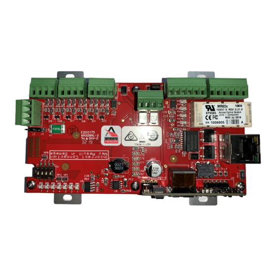
Page 10: Pw7K1R1E Hardware
PW7K1R1E Wiring and Setup PW7K1R1E Hardware 2.1 PW7K1R1E Hardware Figure 2-1: PW7K1R1E Control Board PW7K1R1E www.honeywell.com... -
Page 11: Terminal Connections
PW7K1R1E Wiring and Setup Terminal Connections Figure 2-2: PW7K1R1E Control Board Solder Side STATUS LEDs RLY 2 RLY 1 NC C RELAY K2 (K2) RELAY K1 (K1) ETHERNET STATUS 1 2 3 4 5 6 LEDs 3.3V SOLDER SIDE 2.2 Terminal Connections Table 1: PW7K1R1E Terminal Connections Terminal Acronym... -
Page 12: Jumper Configuration
Factory Use Only Factory Use Only Factory Use Only Factory Use Only PW6K1R1E powered from the Ethernet connection PW6K1R1E powered from an external 12VDC power source connected to TB5-3 (VIN), TB5-4 (GND) Ethernet connection with PoE support Factory Use Only www.honeywell.com... -
Page 13: Dip Switch Configuration
PW7K1R1E Wiring and Setup DIP Switch Configuration 2.4 DIP Switch Configuration The four switches on S1 DIP switch are used to configure the operating mode of the PW7K1R1E. DIP switches are read on power-up except where noted. Definitions Normal operating mode. After initialization, enable default User Name (admin) and Password (password). -
Page 14: Input Power
When powering any remote device(s) by the PW7K1R1E, care must be taken Note: not to exceed the maximum current available. Cable gauge must also be evaluated. See specification section for details. www.honeywell.com... -
Page 15: Input Circuit Wiring
PW7K1R1E Wiring and Setup Input Circuit Wiring Figure 2-3: First Reader Port Wiring 2.11 Input Circuit Wiring Typically, these inputs are used to monitor door position, request to exit, or alarm contact. Input circuits can be configured as unsupervised or supervised. When unsupervised, reporting consists of only the open or closed states. -
Page 16: Relay Circuit Wiring
For this reason, it is recommended that you should use either a diode or MOV (metal oxide varistor) to protect the relay. Wire should be of sufficient gauge to avoid voltage loss. www.honeywell.com... -
Page 17: Status Leds
PW7K1R1E Wiring and Setup Status LEDs Figure 2-5: Relay Circuit Wiring Diagram Diode Selection: • Diode current rating: 1x strike count • Diode breakdown voltage: 4x strike voltage • For 12VDC or 24VDC strike, diode 1N4002 (100V/1A) typical MOV Selection: •... -
Page 18: Security
DIP switches are set to OFF before the PW7K1R1E is commissioned. It is also highly recommended not to configure the PW7K1R1E with an IP address that is accessible from the public Internet www.honeywell.com... -
Page 19: Specifications
PW7K1R1E Wiring and Setup Specifications To further enhance network security, options are available to disable Zeroconf discovery, as well as the web configuration module itself. 2.15 Specifications The interface must be used in low voltage, class 2 circuits only. The installation of this device must comply with all local fire and electrical codes. Power Input •... - Page 20 • 5.5" (140mm) W x 3.63" (92mm) L x 1.33" (34mm) H with bracket Weight • 4 oz. (112g) without bracket • 5 oz. (142g) with bracket UL294, 6th edition Performance Levels Feature Level Stand by Power Endurance Line Security Destructive Attack www.honeywell.com...
-
Page 21: Additional Mounting Information
PW7K1R1E Wiring and Setup Additional Mounting Information 2.16 Additional Mounting Information Sources for the optional items shown below: • 3-gang stainless steel blank cover: Leviton part number 84033-40. Available from Graybar, part number 88158404. • Magnetic switch set: G.R.I. part number: 505. Figure 2-6: Stainless Steel Blank Cover OPTIONAL BLANK COVER W/SCREWS... -
Page 22: Warning
All returns must be accompanied by a Return Material Authorization (RMA) number obtained from customer service, and prepaid postage and insurance. www.honeywell.com... -
Page 23: Liability
PW7K1R1E Wiring and Setup Liability 2.18 Liability The Interface should only be used to control exits from areas where an alternative method for exit is available. This product is not intended for, nor is rated for operation in life-critical control applications. Mercury Security is not liable under any circumstances for loss or damage caused by or partially caused by the misapplication or malfunction of the product. - Page 24 PW7K1R1E Wiring and Setup Liability (This Page was intensionally left blank.) www.honeywell.com...
- Page 25 (This page is left blank intentionally for double-sided printing.)
- Page 26 Discover | Customer Portal Self-Service Product Support and Learning Management System https://honeywelldiscovertraining.com/login/discover/default.asp YouTube | Honeywell Help and Support https://www.youtube.com/channel/UCBEL6ouNV_LN5lEpYRujMTg/featured For more information: www.security.honeywell.com Honeywell Integrated Security 135 W. Forest Hill Avenue Oak Creek, WI 53154 414-766-1700 414-766-1798 Fax European Office...