Honeywell ST 700 User Manual
Smartline pressure transmitters
Hide thumbs
Also See for ST 700:
- User manual (274 pages) ,
- Installation manual (9 pages) ,
- Quick start installation manual (24 pages)
Table of Contents
Quick Links
See also:
User Manual, Installation Manual
Table of Contents

Related Manuals for Honeywell ST 700


Summary of Contents for Honeywell ST 700
- Page 1 ST 700 SmartLine Pressure Transmitters User’s Manual 34-ST-25-44 Revision 2.0 May 2013 Honeywell Process Solutions...
- Page 2 Page ii ST 700 SmartLine Pressure Transmitters User’s Manual Revision 2.0...
- Page 3 In no event is Honeywell liable to anyone for any indirect, special, or consequential damages. The information and specifications in this document are subject to change without notice.
-
Page 4: About This Manual
MC Tookit User Manual, for 400 or later, Document # 34-ST-25-20 PM/APM Smartline Transmitter Integration Manual, Document # PM 12-410 ST 800 & ST 700 Series Pressure, Analog, HART and DE Communications form, Honeywell drawing 50049892 Smart Field Communicator Model STS 103 Operating Guide, Document # 34-ST-11-14 Page iv ST 700 SmartLine Pressure Transmitters User’s Manual... - Page 5 Patent Notice The Honeywell ST 700 SmartLine Pressure Transmitter family is covered by one or more of the following U. S. Patents: 5,485,753; 5,811,690; 6,041,659; 6,055,633; 7,786,878; 8,073,098; and other patents pending. Support and Contact Information For Europe, Asia Pacific, North and South America contact details, refer to the back page of this...
- Page 6 Chassis Ground: Identifies a connection to the chassis or frame of the equipment shall be bonded to Protective Earth at the source of supply in accordance with national and local electrical code requirements. continued Page vi ST 700 SmartLine Pressure Transmitters User’s Manual Revision 2.0...
- Page 7 The Ex mark means the equipment complies with the requirements of the European standards that are harmonised with the 94/9/EC Directive (ATEX Directive, named after the French "ATmosphere EXplosible"). Revision 2.0 ST 700 Smart Pressure Transmitter User’s Manual Page vii...
-
Page 8: Table Of Contents
Safety Integrity Level (SIL) ................... 6 Installation and Startup ........................7 Installation Site Evaluation ....................7 Honeywell MC Toolkit ......................7 Display Installation Precautions ..................... 7 Mounting ST 700 SmartLine Pressure Transmitters .............. 8 3.4.1 Summary ........................8 3.4.2 Mounting Dimensions ....................8 3.4.3... - Page 9 7.2.1 Fault Conditions and Recommended Corrective Actions ..........43 Parts List ............................44 Parts List ............................44 Overview ..........................44 Appendix A. PRODUCT CERTIFICATIONS ..................56 Index ..............................68 Revision 2.0 ST 700 Smart Pressure Transmitter User’s Manual Page ix...
- Page 10 Figure 28 – Electronic Housing, Terminal Block End ................. 48 Figure 29 – Transmitter Major Assemblies ..................49 Figure 30 - ST 700 Models STD710, 720, 730, & 770 ................ 51 Figure 31 – STG730, 740, 770, and STA722, 740 Transmitter Body (Ref.) ........53 Figure 32 –...
- Page 11 Table 17 – Transmitter Major Assemblies ................... 47 Table 18 – ST 700 Models STD710, 720, 730, 770 & STG774 (Ref. Figure 29) ......50 Table 19 - I Parts for STG730, 740, 770 and STA722, 740 Transmitter Body ........52 Table 20 - Inline Gauge and Inline Atmospheric Meter Body Parts ............
- Page 12 Page xii ST 700 SmartLine Pressure Transmitters User’s Manual Revision 2.0...
-
Page 13: Introduction
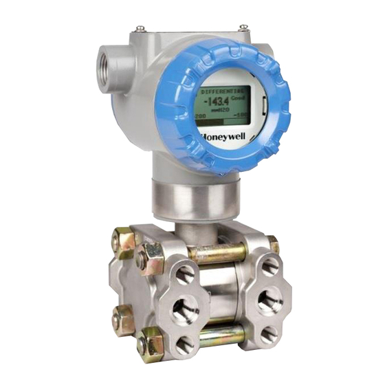
Experion 1.2.1 Physical Characteristics As shown in Figure 1, the ST 700 is packaged in two major assemblies: the Electronics Housing and the Meter Body. The elements in the Electronic Housing respond to setup commands and execute the software and protocol for the different pressure measurement types. Figure 2 shows the assemblies in the Electronics Housing with available options. -
Page 14: Functional Characteristics
Honeywell Multi-Communication (MC) Toolkit (not supplied with the Transmitter) can facilitate setup and adjustment procedures. Certain adjustments can be made through an Experion Station or a Universal Station if the Transmitter is digitally integrated with Honeywell’s Experion or TPS/TDC 3000 control system. -
Page 15: St 700 Transmitter Nameplate
1.5 Transmitter Adjustments Zero and Span adjustments are possible in ST 700 SmartLine Pressure Transmitters with the optional three-button assembly located at the top of the Electronic Housing (see Figure 2). You can also use the Honeywell MC Toolkit or other third-party hand-held zero to make any adjustments to an ST 700 SmartLine Pressure Transmitter. -
Page 16: Display Options
1.6 Display Options The ST 700 SmartLine Pressure Transmitter with Basic Display. Table 2 – Available Display Characteristics Basic Display • Suitable for basic process needs • rotation in 90 Increments • 2 lines, 16 characters • Standard units-of-measurement: Pa, KPa, MPa, KGcm2, TORR, ATM, inH2O, mH2O, bar, mbar, inHg, FTH2O, mmH2O, MMHG, &... -
Page 17: Application Design
2 Application Design 2.1 Overview This section discusses the considerations involved with deploying a Honeywell ST 700 SmartLine Pressure Transmitter in a process system. The following areas are covered: • Safety • Input and output data • Reliability • Environmental limits •... -
Page 18: Safety
2.2 Safety 2.2.1 Safety Integrity Level (SIL) The ST 700 is intended to achieve sufficient integrity against systematic errors by the manufacturer’s design. A Safety Instrumented Function (SIF) designed with this product must not be used at a SIL level higher than the statement, without “prior use” justification by the end user or diverse technology redundancy in the design. -
Page 19: Installation And Startup
3 Installation and Startup 3.1 Installation Site Evaluation Evaluate the site selected for the ST 700 Transmitter installation with respect to the process system design specifications and Honeywell’s published performance characteristics for your particular model. Some parameters that you may want to include in your site evaluation are: •... -
Page 20: Mounting St 700 Smartline Pressure Transmitters
Transmitter models, except flush mounts and those with integral flanges, can be attached to a two- inch (50 millimeter) vertical or horizontal pipe using Honeywell’s optional angle or flat mounting bracket; alternately you can use your own bracket. Flush-mount models are attached directly to a process pipe or tank by a one-inch weld nipple. -
Page 21: Bracket Mounting Procedure
See the STAxxL) following example. Mounting holes in the end of the process Dual-head GP and AP head. EXAMPLE: Inline model mounted to an optional angle bracket. See Figure 6. Revision 2.0 ST 700 Smart Pressure Transmitter User’s Manual Page 9... -
Page 22: Figure 6 - Inline Model Mounted To An Optional Bracket
O) for a Draft Range Transmitter can result from a mounting position that is rotated 90 from the vertical. A typical zero-shift of 0.12 mmHg or 0.20 inH can occur for a five (5)-degree rotation from the vertical. Page 72 ST 700 SmartLine Pressure Transmitters User’s Manual Revision 1.0... -
Page 23: Mounting Transmitters With Small Absolute Or Differential Pressure Spans
Transmitter side-to-side and front-to-back. Figure 8 shows how to level a Transmitter using a spirit level. Figure 8 – Using a Spirit Balance to Level a Transmitter Revision 2.0 ST 700 Smart Pressure Transmitter User’s Manual Page 11... -
Page 24: Flange Mounting
• To prevent performance degradation in extended-mount flanged Transmitters, ensure that sufficient clearance exists in front of the sensing diaphragm body. Figure 9 – Tank-Flange Mounted Transmitter Page 72 ST 700 SmartLine Pressure Transmitters User’s Manual Revision 1.0... -
Page 25: Remote Diaphragm Seal Mounting Information
Model Variable Head Fixed or Constant Head Transmitter High Pressure (HP) Side Transmitter Low Pressure (LP) side to tank STR73D to tank wall lower flange mounting. wall upper flange. Revision 2.0 ST 700 Smart Pressure Transmitter User’s Manual Page 13... -
Page 26: Piping The St 700 Transmitter
Blow-Down Blow-Down Piping Piping To Low Pressure To High Pressure Side of Transmitter Side of Transmitter To Waste To Waste Figure 11 – Typical 3-Valve Manifold with Blow-Down Piping Page 72 ST 700 SmartLine Pressure Transmitters User’s Manual Revision 1.0... -
Page 27: Suggestions For Transmitter Location
NOTE: The threaded hole in each Flange Adapter is offset from center. To ensure proper orientation for re-assembly, note the orientation of the offset relative to each Process Head before removing any adapter. Revision 2.0 ST 700 Smart Pressure Transmitter User’s Manual Page 15... -
Page 28: Wiring A Transmitter
Loop wiring is connected to the Transmitter by simply attaching the positive (+) and negative (–) loop wires to the positive (+) and negative (–) terminals on the Transmitter terminal block in the Electronics Housing shown in Figure 14. Page 72 ST 700 SmartLine Pressure Transmitters User’s Manual Revision 1.0... -
Page 29: Figure 14 - Transmitter 3-Screw Terminal Board And Grounding Screw
– V LOOP MAX SUPPLY MIN XMTR MIN In this calculation: = 10.8 V + V XMTR MIN = 1.1 V, lightning protection option, LP = 2.3 V, remote meter Revision 2.0 ST 700 Smart Pressure Transmitter User’s Manual Page 17... -
Page 30: Digital System Integration Information
The positive and negative loop wires are connected to the positive (+) and negative (–) terminals on the terminal block in the Transmitter Electronics Housing. Barriers can be installed per Honeywell’s instructions for Transmitters to be used in intrinsically safe applications. -
Page 31: Process Sealing
3.6.7 Process Sealing The ST 700 SmartLine Pressure Transmitter is CSA-certified as a Dual Seal device in accordance with ANSI/ISA–12.27.01–2003, “Requirements for Process Sealing Between Electrical Systems and Flammable, or Combustible Process Fluids.” 3.6.8 Explosion-Proof Conduit Seal When installed as explosion proof in a Division 1 Hazardous Location, keep covers tight while the Transmitter is energized. -
Page 32: Output Check Procedures
The Transmitter does not measure the given PV input or update the PV output while it operates in the Output mode. 3.7.4 Constant Current Source Mode Procedure Figure 15 – Current Loop Test Connections Page 72 ST 700 SmartLine Pressure Transmitters User’s Manual Revision 1.0... - Page 33 8. To view the monitor display, navigate back from the LOOP TEST display, and select the MONITOR display. A Confirm popup will be displayed. 9. Select Yes to continue. This concludes the Startup procedure. Revision 2.0 ST 700 Smart Pressure Transmitter User’s Manual Page 21...
-
Page 34: Operation
HART operation using the 3-button option. 4.2 Three-Button Operation The ST 700 optional three-button interface provides a user interface and operation capability without opening the transmitter. Figure 16 shows the location of the three-button option and the labels for each button. -
Page 35: The Basic Display Menu
None ↑ and ↓ to Select the PV decimal resolution to PV Decimal be shown on selected screen from select from X.XX list. list X.XXX Revision 2.0 ST 700 Smart Pressure Transmitter User’s Manual Page 23... - Page 36 Fixed Output Mode, as 12.000 removed from indicated by the flashing output Automatic Control value. Navigation away from this menu item will return the loop to Normal (Automatic) Mode. Page 72 ST 700 SmartLine Pressure Transmitters User’s Manual Revision 1.0...
- Page 37 This item is only available when the Transfer Function is set to Square Root. Enter the low flow cutoff point when Flow Breakpoint ##. #% Single Breakpt is selected. Range: 0 to 25.0 %Flow. Revision 2.0 ST 700 Smart Pressure Transmitter User’s Manual Page 25...
-
Page 38
Electronics Module and the Meter Read Only Meterbody body Parameter HART Menu item shows the Protocol communications protocol Identifies the type and range of the Read Only Model Key transmitter Parameter
Page 72 ST 700 SmartLine Pressure Transmitters User’s Manual Revision 1.0... -
Page 39: Data Entry
2. Press the or buttons to scroll through the list of choices. ↵ Press to make your selection. The new selection will be stored in the transmitter and will be displayed on the lower line, right justified. Revision 2.0 ST 700 Smart Pressure Transmitter User’s Manual Page 27... -
Page 40: Three Button Operation With No Display Installed
) and Span ( ) buttons together to set the span. 4. Verify that the PV output is now 20 mA. You can also use the MCT 202 Toolkit to make any adjustments to an ST 700 SmartLine Pressure Transmitter. Alternately, certain adjustments are possible through an Experion Station or Universal Station, if the ST 700 is digitally integrated with either of these stations. -
Page 41: Procedure To Establish Failsafe Operation
The following procedure outlines the steps for positioning the write protect and failsafe jumpers on the electronics module. See Figure 17 for the locations of the failsafe and write protect jumpers. Figure 17 – Locating the Failsafe and Write Protect Jumpers Revision 2.0 ST 700 Smart Pressure Transmitter User’s Manual Page 29... -
Page 42: Table 11 - Hart And De Failsafe And Write Protect Jumpers
5. Set the Failsafe Jumper (top jumper) to the desired position (UP or DOWN). See Table 11 and Table 12 for jumper positioning. 6. If applicable, re-install the Display module as follows: • Orient the display as desired. Page 72 ST 700 SmartLine Pressure Transmitters User’s Manual Revision 1.0... - Page 43 Orient the Display for proper viewing through the end cap window. You can rotate the meter mounting orientation in 90 increments. 7. Restore transmitter power if removed. Revision 2.0 ST 700 Smart Pressure Transmitter User’s Manual Page 31...
-
Page 44: Monitoring The Basic Display
Process Variable Tag is user-configurable from a HART Host. This field has 14 characters. • Engineering Units. This field is user-configurable. This field has 8 characters. Figure 18 – Basic Display with Process Variable Format Page 72 ST 700 SmartLine Pressure Transmitters User’s Manual Revision 1.0... -
Page 45: Maintenance
5.2 Preventive Maintenance Practices and Schedules The ST 700 Transmitter does not require any specific maintenance at regularly scheduled intervals. However, it is recommended that you perform these typical inspection and maintenance routines on a schedule that is dictated by the characteristics of the process medium and if blow-down facilities or purge systems are being used. -
Page 46: Figure 19 - Dp Transmitter Head Disassembly
8. Inspect the barrier diaphragm for signs of deterioration, corrosion, and distortion. 9. If the diaphragm is distorted contact Honeywell for assistance. 10. Install a new gasket/O-ring in each process head. 11. Coat threads on the process head bolts with a suitable anti-seize compound, such as “Neverseize,”... -
Page 47: Figure 20 - Head Bolt Tightening Sequence
Figure 20 – Head Bolt Tightening Sequence Table 13 – Head Bolt Torque Values Revision 2.0 ST 700 Smart Pressure Transmitter User’s Manual Page 35... -
Page 48: Replacing The Communication Module
2. Loosen the end cap lock, and unscrew the end cap from the electronics side of the Transmitter housing. 3. If equipped with a Display module, carefully depress the two tabs on the sides of the Display Module, and pull it off. Page 72 ST 700 SmartLine Pressure Transmitters User’s Manual Revision 1.0... - Page 49 (Steps 13 - 16 required for Field Upgrades Only) 13. Loosen the End Cap locking screw and unscrew the End Cap from the Field Wiring side of the transmitter housing. Revision 2.0 ST 700 Smart Pressure Transmitter User’s Manual Page 37...
-
Page 50: Replacing The Meter Body
18. Check the settings of the Transmitter Setup and Display Setup parameters to make sure that the transmitter is configured correctly for your application. See the User's Manual (ST 800 #34-ST-25-35, ST 700 #34-ST-25-44) for details on HART and DE transmitters. Refer to manual #34-ST-25-39 for additional information about Fieldbus transmitters. -
Page 51: Figure 23 - Hardware Location To Remove The Meter Assembly
To prevent damage to the diaphragm in the Meter Body, use extreme care when handling or placing the Meter Body on any surface. Carefully assemble gaskets or O-rings to the meter body. If installing O-rings, lubricate with water or leave dry. Revision 2.0 ST 700 Smart Pressure Transmitter User’s Manual Page 39... -
Page 52: Figure 24 - Meter Body Reassembly
16. Use a torque wrench to gradually tighten nuts to torque rating in sequence shown in Figure 25. Tighten head bolts in stages of 1/3 full torque, 2/3 full torque, and then full torque. Figure 25 – Head Bolt Tightening Sequence Page 72 ST 700 SmartLine Pressure Transmitters User’s Manual Revision 1.0... - Page 53 29. Verify the Transmitter configuration data. Restore the saved database if necessary. 30. Lubricate the end-cap O-ring with Parker Super O-ring silicone lubricant or equivalent before replacing the end caps. Revision 2.0 ST 700 Smart Pressure Transmitter User’s Manual Page 41...
-
Page 54: Calibration
For a Transmitter operating in analog mode, you must calibrate its output signal measurement range using any compatible hand-held communicator or a local display. One calibration option is to use the Honeywell Smart Field Communicator (SFC). Refer to the Smart Field Communicator Operating Guide, 34-ST-11-14 for calibration procedures. -
Page 55: Troubleshooting
However, this section covers the diagnostic messages that indicate critical conditions. Other than the critical conditions, additional detail is not provided. If you require assistance, contact your distributor or Honeywell Technical Support. All other messages are covered by the MC Toolkit Users’ Manual. 7.2 Critical Diagnostics Screens The Basic Display will display the message CRITCAL FAULT on the top line of the LCD and the appropriate diagnostic text on the lower line. -
Page 56: Parts List
HART/DE Terminal Block Assy Without Lightning Protection 50075472-532 HART/DE Terminal Block Assy With Lightning Protection Figure 50075472-533 FieldBus Terminal Block Assy Without Lightning Protection 50075472-534 FieldBus Terminal Block Assy With Lightning Protection Page 72 ST 700 SmartLine Pressure Transmitters User’s Manual Revision 1.0... -
Page 57: Figure 26 - Angle And Flat Bracket Parts
Specify DP Models complete GP/AP HEAD Models model LGP/LAP Models Figure 29 number from Flush Mount Models nameplate Flange Mount Models Figure 26 – Angle and Flat Bracket Parts Revision 2.0 ST 700 Smart Pressure Transmitter User’s Manual Page 45... -
Page 58: Table 16 - Angle And Flat Bracket Parts
SS 316 Flat Bracket Mounting kit for all In-line transmitters 51196557-008 except In-Line and Flush mount transmitters SS 316 Flat Bracket Mounting kit for all In-Line and Flush 51196557-009 mount transmitters Page 72 ST 700 SmartLine Pressure Transmitters User’s Manual Revision 1.0... -
Page 59: Figure 27 - Electronic Housing, Display End
FF Electronics Module Assembly (PWA) without Reed sensor 50049849-510 FF Electronics Module Assembly (PWA) with Reed sensor 50049915-501 External Zero, Span & Config Buttons 30757503-005 Electronics housing seals kit (includes O-rings) Revision 2.0 ST 700 Smart Pressure Transmitter User’s Manual Page 47... -
Page 60: Figure 28 - Electronic Housing, Terminal Block End
Figure 28 – Electronic Housing, Terminal Block End Page 72 ST 700 SmartLine Pressure Transmitters User’s Manual Revision 1.0... -
Page 61: Figure 29 - Transmitter Major Assemblies
Figure 29 – Transmitter Major Assemblies Revision 2.0 ST 700 Smart Pressure Transmitter User’s Manual Page 49... -
Page 62: Table 18 - St 700 Models Std710, 720, 730, 770 & Stg774 (Ref. Figure 29)
Table 18 – ST 700 Models STD710, 720, 730, 770 & STG774 (Ref. Figure 29) Part Number Description Qty/Unit Vent and Plug Kits 30753785-001 Drain and Plug Kit, stainless steel 30753787-001 Drain and Plug Kit, Monel 30753786-001 Drain and Plug Kit, Hastelloy C... -
Page 63: Figure 30 - St 700 Models Std710, 720, 730, & 770
Figure 30 - ST 700 Models STD710, 720, 730, & 770 (Refer to Table 18) Revision 2.0 ST 700 Smart Pressure Transmitter User’s Manual Page 51... -
Page 64: Table 19 - I Parts For Stg730, 740, 770 And Sta722, 740 Transmitter Body
Note 2: The Kit for Process Heads without side vent/drain does not include Pipe Plugs (K1). Reference Head 51452951-201 Carbon Steel Blind Reference Head 51452951-101 316 SS Blind Reference Head Page 72 ST 700 SmartLine Pressure Transmitters User’s Manual Revision 1.0... -
Page 65: Figure 31 - Stg730, 740, 770, And Sta722, 740 Transmitter Body (Ref.)
Figure 31 – STG730, 740, 770, and STA722, 740 Transmitter Body (Ref.) Table 20 - Inline Gauge and Inline Atmospheric Meter Body Parts Part Number Description Qty/Unit Specify complete ST Series replacement meter body (LAP/LGP model) model number from nameplate Revision 2.0 ST 700 Smart Pressure Transmitter User’s Manual Page 53... -
Page 66: Figure 32 - Inline Gauge And Inline Atmospheric Meter Body Bodies
Flange adapter kit (Hastelloy C flange adapter with 316 st. 30754419-023 steel bolts) Bolt, hex head, 7/16-20 UNF, 1.375 inches lg. Flange adapter Gasket Housing seal kit 30757503-001 Page 72 ST 700 SmartLine Pressure Transmitters User’s Manual Revision 1.0... - Page 67 Figure 33 – Flange Mounted Meter Body Revision 2.0 ST 700 Smart Pressure Transmitter User’s Manual Page 55...
-
Page 68: Appendix A. Product Certifications
A1. Safety Instrumented Systems (SIS) Installations For Safety Certified Installations, please refer to SmartLine Safety Manual 34-ST-25-37 for installation procedure and system requirements. A2. European Directive Information (CE Mark) Page 72 ST 700 SmartLine Pressure Transmitters User’s Manual Revision 1.0... - Page 69 Revision 2.0 ST 700 Smart Pressure Transmitter User’s Manual Page 57...
- Page 70 Page 72 ST 700 SmartLine Pressure Transmitters User’s Manual Revision 1.0...
- Page 71 Revision 2.0 ST 700 Smart Pressure Transmitter User’s Manual Page 59...
- Page 72 Standards: ANSI/ ISA 60079-0: 2009 ; CAN/ CSA-C22.2 No. 0-M91:2006; CAN/ CSA- E60079-0:2002 ; ANSI/ UL 913 : 2010 ; ANSI/ ISA 60079-11 : 2009 ; CAN/ CSA-C22.2 No.157-92: 1992; CAN/CSA-E 60079-11: 2002; ANSI/ ISA 60079-26 : 2008 Page 72 ST 700 SmartLine Pressure Transmitters User’s Manual Revision 1.0...
- Page 73 DE/ HART/ IECEx- CSA Enclosure: IP66/ IP67 Standards: IEC 60079-0: 2011 IEC 60079-11 : 2011 IEC 60079-26 : 2006 IEC 60079-15 : 2011 IEC 60529 : 2009 with Corr 3 Revision 2.0 ST 700 Smart Pressure Transmitter User’s Manual Page 61...
-
Page 74: Warnings And Cautions
Non-Incendive Equipment: WARNING: DO NOT OPEN WHEN AN EXPLOSIVE ATMOSPHERE MAYBE PRESENT All Protective Measures: WARNING: FOR CONNECTION IN AMBIENTS ABOVE 60 o C USE WIRE RATED 105 o C Page 72 ST 700 SmartLine Pressure Transmitters User’s Manual Revision 1.0... - Page 75 Consult the manufacturer for dimensional information on the flameproof joints for repair. Painted surface of the ST 700 may store electrostatic charge and become a source of ignition in applications with a low relative humidity less than approximately30% relative humidity where the painted surface is relatively free of surface contamination such as dirt, dust or oil.
- Page 76 Page 72 ST 700 SmartLine Pressure Transmitters User’s Manual Revision 1.0...
- Page 77 Revision 2.0 ST 700 Smart Pressure Transmitter User’s Manual Page 65...
- Page 78 Page 72 ST 700 SmartLine Pressure Transmitters User’s Manual Revision 1.0...
- Page 79 Smart Field Communicator STIM Pressure Transmitter Interface Module STIMV IOP Pressure Transmitter Interface Multivariable Input/Output Processor Thermocouple Upper Range Limit Upper Range Value Universal Station Volts Alternating Current Volts Direct Current Revision 2.0 ST 700 Smart Pressure Transmitter User’s Manual Page 67...
-
Page 80: Index
Changing the Default Failsafe Direction ......28 Remote Diaphragm Seal .......... 13 DE and Analog Differences ........28 Mounting ST 700 SmartLine Pressure Transmitters ..8 Failsafe Operation ............ 29 Mounting Dimentsions ..........8 Copyrights, Notices and Trademarks ......iii Summary .............. - Page 81 Data Entry ..............27 Transmitter Adjustments ..........3 Troubleshooting ............43 Critical Diagnostics Screens ........43 Wiring a Transmitter ............. 16 Wiring Procedure ............. 18 Wiring Variations ............. 18 Revision 2.0 ST 700 Smart Pressure Transmitter User’s Manual Page 69...
- Page 82 For application assistance, current specifications, pricing, or name of the nearest Authorized Distributor, contact one of the offices below. ASIA PACIFIC EMEA NORTH AMERICA SOUTH AMERICA (TAC) Honeywell Process Honeywell Process Honeywell do Brazil & Cia hfs-tac- Solutions, Solutions, Phone: +(55-11) 7266- [email protected] Phone: + 80012026455 or Phone: 1-800-423-9883 1900...