Honeywell ST 3000 User Manual
Smart transmitter release 300 and smart field communicator model sts103
Hide thumbs
Also See for ST 3000:
- User manual (314 pages) ,
- Installation manual (126 pages) ,
- Specification and model selection manual (36 pages)

Related Manuals for Honeywell ST 3000


Summary of Contents for Honeywell ST 3000
- Page 1 ST 3000 Smart Transmitter Release 300 and Smart Field Communicator Model STS103 User’s Manual 34-ST-25-14 6/05...
- Page 2 In no event is Honeywell liable to anyone for any indirect, special or consequential damages. The information and specifications in this document are subject to change without notice.
-
Page 3: Patent Notice
) as the operator interface for the ST 3000 transmitter. Be aware that data in this manual overlaps information in the ST 3000 Smart Transmitter Installation Guide and the Smart Field Communicator Model STS103 Operating Guide to minimize cross reference. -
Page 4: References
(green or green/yellow) supply system conductor. Earth Ground. Functional earth connection. NOTE: This connection shall be bonded to Protective earth at the source of supply in accordance with national and local electrical code requirements. ST 3000 Release 300 and SFC Model STS103 User’s Manual 6/05... -
Page 5: Table Of Contents
Mounting ST 3000 Transmitter ......................26 Piping ST 3000 Transmitter......................38 Wiring ST 3000 Transmitter......................43 SECTION 5 —GETTING STARTED ................50 Introduction ............................50 Establishing Communications ......................51 Making Initial Checks........................55 Changing Mode of Operation ......................58 6/05 ST 3000 Release 300 and SFC Model STS103 User’s Manual... - Page 6 Monitoring Local Smart Meter Display ..................163 SECTION 9 —MAINTENANCE ..................169 Introduction ........................... 169 Preventive Maintenance........................ 170 Inspecting and Cleaning Barrier Diaphragms ................171 Replacing PWA ..........................175 Replacing Meter Body........................178 ST 3000 Release 300 and SFC Model STS103 User’s Manual 6/05...
- Page 7 APPENDIX D – HAZARDOUS LOCATIONS REFERENCE ......... 253 North American Classification of Hazardous Locations ..............253 International Electrotechnical Commission (IEC) Classification of Hazardous Locations ....259 Enclosure Ratings .........................263 INDEX..........................265 6/05 ST 3000 Release 300 and SFC Model STS103 User’s Manual...
- Page 8 Typical Arrangement for Pressure Measurement with Flush Mount Transmitter ......144 Figure 46 Typical Arrangement for Liquid Level Measurement with Flush Mount Transmitter.......144 Figure 47 Typical Piping Arrangement for Pressure Measurement with AP Type Transmitter......145 viii ST 3000 Release 300 and SFC Model STS103 User’s Manual 6/05...
- Page 9 Figure B-8 Piping Installation for Differential Pressure Transmitter and Impulse Piping with Steam Heating...247 Figure B-9 Piping Installation for Process Pressure Transmitter and Impulse Piping with Steam Heating..248 6/05 ST 3000 Release 300 and SFC Model STS103 User’s Manual...
- Page 10 Summary of Keystrokes for Operation Data Access................152 Table 47 Cutting Failsafe Direction Jumper....................156 Table 48 Writing Data in Scratch Pad Area ....................157 Table 49 Saving and Restoring a Database .....................160 ST 3000 Release 300 and SFC Model STS103 User’s Manual 6/05...
- Page 11 Table D-4 Standards Australia (LOSC) Certification..................262 Table D-5 Zone 2 (Europe) Declaration of Conformity ..................262 Table D-6 NEMA Enclosure Type Numbers and Comparable IEC Enclosure Classification ......264 6/05 ST 3000 Release 300 and SFC Model STS103 User’s Manual...
- Page 12 PSIA ....................Pounds per Square Inch Absolute RFI.......................Radio Frequency Interference SFC......................Smart Field Communicator TPS ........................TotalPlant Solution URL........................Upper Range Limit URV ........................Upper Range Value Vdc ........................Volts Direct Current XMTR ..........................Transmitter ST 3000 Release 300 and SFC Model STS103 User’s Manual 6/05...
-
Page 13: Technical Assistance
Technical Assistance If you encounter a problem with your ST 3000 Smart Transmitter, check to see how your transmitter is currently configured to verify that all selections are consistent with your application. If the problem persists, you can reach Honeywell’s Solution Support Center for technical support by telephone during normal business hours. -
Page 15: Section 1 -Overview - First Time Users Only
ST 3000 Smart Transmitter and its companion operator interface device the hand-held Smart Field Communicator (SFC ) before. It provides some general information to acquaint you with the ST 3000 transmitter and the SFC. Honeywell also offers the SCT 3000 Smartline Configuration Toolkit ATTENTION that runs on a variety of Personal Computer (PC) platforms using MS- DOS 5.0 or higher and Windows 3.1 or higher. -
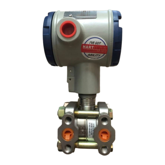
Page 16: St 3000 Smart Transmitters
Electronics Housing Meter Body The ST 3000 can transmit its output in either an analog 4 to 20 milliampere format or a digital DE protocol format for direct digital communications with our TPS system, Allen-Bradley PLCs and other control systems. - Page 17 When the transmitter is in its DE mode, the process variable is available for monitoring and control purposes; and the meter body temperature is also available as a secondary variable for monitoring purposes only. See Figure 3. Continued on next page 6/05 ST 3000 Release 300 and SFC Model STS103 User’s Manual...
- Page 18 20 mA loop. Modular Electronics Terminal Block Pressure Series and model Honeywell’s line of ST 3000 Smart Transmitters includes these two number data series designations: • Series 100 • Series 900 Each series includes several models to meet various process pressure measurement and interface requirements.
- Page 19 ATTENTION 100, Series 100e, Series 600, and Series 900 have been supplied at various times since the ST 3000 was introduced in 1983. While all these transmitters are functionally alike, there are differences in housing and electronics design. This manual only applies for Release 300, Series 100 transmitters with software version 3.0 or greater and Release 300, Series...
-
Page 20: Table 1 St 3000 Pressure Transmitter Family
Flange on One Side Dual-Head Gauge Not Available STG9xx Pressure In-Line Gauge and STG1xL STG9xL Absolute Pressure STA1xL STA9xL Gauge and Absolute STG1xx STG9xx Pressure STA1xx STA9xx Continued on next page ST 3000 Release 300 and SFC Model STS103 User’s Manual 6/05... - Page 21 Series 100 Model Series 900 Model Flange-Mount STF1xx STF9xx Liquid Level Differential Pressure STR1xx STR9xx with Remote Diaphragm Seals Flush Mount Not Available STG93P STG14T High Temperature Not Available STF14T 6/05 ST 3000 Release 300 and SFC Model STS103 User’s Manual...
-
Page 22: Smart Field Communicator
Retrieve and display data from the transmitter or SFC memory. • Change Mode of Operation: Tell transmitter to operate in either its analog (4-20 mA) mode or its digital enhanced (DE) mode. Continued on next page ST 3000 Release 300 and SFC Model STS103 User’s Manual 6/05... - Page 23 STT 3000 configuration parameters for STT temperature transmitters, if 3000 and scratch pad SFC software version is 5.0 configuration area for ST 3000. or greater. Continued on next page 6/05 ST 3000 Release 300 and SFC Model STS103 User’s Manual...
- Page 24 Smart Field Communicator Operating Guide 34-ST-11-10 for keystroke details. But, be aware that transmitter functions will be limited to only those that are supported by the Model STS102 SFC. ST 3000 Release 300 and SFC Model STS103 User’s Manual 6/05...
-
Page 25: Transmitter/Sfc Order
ST 3000 transmitter and SFC order. Figure 5 Typical ST 3000 Transmitter and SFC Order Components. Ordered Series 100 ST 3000 Differential pressure transmitter with optional mounting bracket Smart Field Communicator with optional battery charger Received Shipped ST 3000... - Page 26 ST 3000 transmitter. This is the main reference manual for the ST 3000 transmitter and it overlaps some data in the previously listed Installation Guide 34-ST-33-39 and in the following Operating Guide 34-ST-11-14 to minimize cross reference.
-
Page 27: Local Smart Meter Options
SEL. VALUE Yes * SPAN UNITS ZERO LOWER VALUE Local Zero and Span Adjustments only Yes * SPAN ZERO * Except draft range, model STD110 Continued on next page 6/05 ST 3000 Release 300 and SFC Model STS103 User’s Manual... -
Page 28: Figure 6 St 3000 With Local Smart Meter Option
See Figure 6. Figure 6 ST 3000 with Local Smart Meter Option. Electronics Housing Local Smart Meter Option ST 3000 Release 300 and SFC Model STS103 User’s Manual 6/05... -
Page 29: Section 2 -Quick Start Reference
Getting ST 3000 Transmitter On-Line Quickly ......16 About this section This section assumes that the ST 3000 transmitter has been installed and wired correctly, and is ready to be put into operation. It also assumes that you are somewhat familiar with using the SFC and that the transmitter has been configured correctly for your application. -
Page 30: Getting St 3000 Transmitter On-Line Quickly
Getting ST 3000 Transmitter On-Line Quickly Quick start-up tasks Table 4 lists common start-up tasks for an ST 3000 transmitter using an SFC and gives an appropriate section in this manual to reference for more information about how to do the task. The start-up tasks are listed in the order they are commonly completed. -
Page 31: Section 3 -Preinstallation Considerations
This section reviews things you should take into consideration before you install the transmitter and start using the SFC. Of course, if you are replacing an existing ST 3000 transmitter and you did not order a new SFC; you can skip this section. -
Page 32: Ce Conformity (Europe) Notice
(98 feet) to the antenna(e). In special cases, when highly susceptible apparatus is used in close proximity, the user may have to employ additional mitigating measures further reduce electromagnetic emissions of this equipment. ST 3000 Release 300 and SFC Model STS103 User’s Manual 6/05... -
Page 33: Considerations For St 3000 Transmitter
Considerations for ST 3000 Transmitter The ST 3000 transmitter is designed to operate in common indoor Evaluate conditions industrial environments as well as outdoors. To assure optimum performance, evaluate these conditions at the mounting area relative to published transmitter specifications and accepted installation practices for electronic pressure transmitters. - Page 34 Table 5 lists the operating temperature limits for the various types of transmitters with silicone fill fluids. See transmitter specifications for temperature limits of ST 3000 transmitters with alternative fill fluids. Table 5 Operating Temperature Limits (Transmitters with Silicone Fill Fluids)
- Page 35 For more specific information, refer to the appropriate Specification and Model Selection Guide or transmitter nameplate NOTE: To convert bar values to kilopascals (kPa), multiply by 100. For example, 3.5 bar equals 350 kPa. 6/05 ST 3000 Release 300 and SFC Model STS103 User’s Manual...
-
Page 36: Considerations For Sfc
The SFC battery charger is not intrinsically safe. Always recharge the SFC battery pack in a nonhazardous location. The SFC itself is an intrinsically safe device. Continued on next page ST 3000 Release 300 and SFC Model STS103 User’s Manual 6/05... - Page 37 • Be sure the power supply voltage does not exceed 45Vdc. The ST 3000 transmitter and SFC were designed to operate with voltages below 45Vdc. • Be sure there is at least 250 ohms of resistance between the SFC and the power supply for proper communications.
-
Page 38: Considerations For Local Smart Meter Option
°C (-4 °F) the display becomes unreadable due to slow response of the LCD. This is also only temporary and normal readability will return when temperature returns above -20 °C (-4 °F). ST 3000 Release 300 and SFC Model STS103 User’s Manual 6/05... -
Page 39: Section 4 -Installation
Wiring ST 3000 Transmitter ............41 About this section This section provides information about installing the ST 3000 transmitter. It includes procedures for mounting, piping and wiring the transmitter for operation. 6/05 ST 3000 Release 300 and SFC Model STS103 User’s Manual... -
Page 40: Typical Bracket Mounted And Flange Mounted Installations
Figure 8 Typical Bracket Mounted and Flange Mounted Installations Angle Flat Mounting Mounting Bracket Bracket Horizontal Pipe Tank Wall Flange Transmitter Connection Flange 24118 Continued on next page ST 3000 Release 300 and SFC Model STS103 User’s Manual 6/05... - Page 41 Example - Angle mounting bracket secured to horizontal or vertical pipe. Nuts and Nuts and Lockwashers Lockwashers Mounting Bracket U-Bolt Mounting Bracket Horizontal Pipe Vertical Pipe U-Bolt Continued on next page 6/05 ST 3000 Release 300 and SFC Model STS103 User’s Manual...
- Page 42 NOTE: If the meter body is hexagonal, you must use the additional bracket supplied. If meter body is round, discard the bracket. Continued on next page ST 3000 Release 300 and SFC Model STS103 User’s Manual 6/05...
- Page 43 The metric socket head wrench kit supplied with the SFC includes 2.5, 3, and 4mm size wrenches. You will need the 4mm size wrench for the outside set screw. Continued on next page 6/05 ST 3000 Release 300 and SFC Model STS103 User’s Manual...
-
Page 44: Mounting St 3000 Transmitter
Figure 9 Leveling an Absolute Pressure Transmitter. Leveling Absolute Pressure models Center Section Process Head Position spirit balance on center section of meter body only. Cont’d Continued on next page ST 3000 Release 300 and SFC Model STS103 User’s Manual 6/05... - Page 45 Continued Figure 9 Leveling an Absolute Pressure Transmitter (cont’d) Leveling Inline models Mount transmitter vertically to assure best accuracy. Position spirit balance on pressure connection surface of AP body. 6/05 ST 3000 Release 300 and SFC Model STS103 User’s Manual...
-
Page 46: Table 10 Zero Corrects Procedure For Std110
Zero input is set equal to applied input pressure. Remove the tube from between the input connections, the power, and the digital voltmeter or SFC. Continue with the remaining installation tasks. Continued on next page ST 3000 Release 300 and SFC Model STS103 User’s Manual 6/05... -
Page 47: Typical Flange Mounted Transmitter Installation
Attention: Dotted area indicates use with closed tank with reference leg. Maximum Level Variable Reference Head H1 Minimum Level HP Side LP Side vented mounted to atmosphere to tank Continued on next page 6/05 ST 3000 Release 300 and SFC Model STS103 User’s Manual... -
Page 48: Figure 11 Typical Flush Mounted Transmitter Installation
On insulated tanks, remove enough insulation to accommodate the mounting sleeve. Figure 11 Typical Flush Mounted Transmitter Installation 1” Pipe Mount - 316 SS Weld Nipple (standard option) Continued on next page ST 3000 Release 300 and SFC Model STS103 User’s Manual 6/05... -
Page 49: Typical Pipe And Flange Mounted Installations
On insulated tanks, remove enough insulation to accommodate the ATTENTION flange extension. Figure 12 Typical Pipe and Flange Mounted Installations Tank Wall Flange Transmitter Connection Flange Process Pipe 1/2" NPT Connection Continued on next page 6/05 ST 3000 Release 300 and SFC Model STS103 User’s Manual... -
Page 50: Table 11 Mounting Remote Diaphragm Seal Transmitter
(LP) side of transmitter to lower flange mounting on tank wall for variable head H1. ATTENTION On insulated tanks, remove enough insulation to accommodate the flange extension. Continued on next page ST 3000 Release 300 and SFC Model STS103 User’s Manual 6/05... -
Page 51: Figure 13 Typical Remote Diaphragm Seal Transmitter Installation
- Model STR12D HP Side - Model STR13D Maximum Level Variable Fixed Head H1 Ref. Leg Minimum Level HP Side - Model STR93D - Model STR12D LP Side - Model STR13D 6/05 ST 3000 Release 300 and SFC Model STS103 User’s Manual... -
Page 52: Piping St 3000 Transmitter
3-Valve Valve Valve Manifold Blow-Down Blow-Down Piping Piping To Low Pressure To High Pressure Side of Transmitter Side of Transmitter To Waste To Waste 21010 Continued on next page ST 3000 Release 300 and SFC Model STS103 User’s Manual 6/05... - Page 53 For gas measurement, use a condensate leg and drain at the low point (freeze protection may be required here). See Appendix B for some suggested freeze protection solutions. 6/05 ST 3000 Release 300 and SFC Model STS103 User’s Manual...
- Page 54 See Model Selection Guide for description of available Diaphragm Seals Flanged, Threaded, Chemical Tee, Saddle, and Sanitary process connections. * Reference side has standard differential pressure process head. Continued on next page ST 3000 Release 300 and SFC Model STS103 User’s Manual 6/05...
-
Page 55: Table 14 Flange Description
• Be sure all the valves in the blow-down lines are closed tight after the initial blow-down procedure and each maintenance procedure after that. Continued on next page 6/05 ST 3000 Release 300 and SFC Model STS103 User’s Manual... - Page 56 Evenly torque flange adapter bolts to a torque of 27,1 Nm +/- 1,4 Nm (20 ft lbs +/- 1.0 ft lbs) ST 3000 Release 300 and SFC Model STS103 User’s Manual 6/05...
-
Page 57: Wiring St 3000 Transmitter
Figure 17 shows the 5-screw terminal block used when the lightning protection option is ordered. Continued on next page 6/05 ST 3000 Release 300 and SFC Model STS103 User’s Manual... -
Page 58: St 3000 Transmitter Terminal Block
3000 system bookset. Allen-Bradley PLC If you are digitally integrating the ST 3000 to an Allen Bradley PLC, the same FTA and wiring procedures used with Honeywell’s TPS system are also used with the Allen-Bradley 1771 and 1746 platforms. For more information, contact: ProSoft Technology, Inc. - Page 59 SIGNAL – terminal. Example – Connecting loop power to transmitter. 3-screw terminal block 5-screw terminal (option LP) Loop Loop Power Power Replace end-cap, and tighten end-cap lock. Continued on next page 6/05 ST 3000 Release 300 and SFC Model STS103 User’s Manual...
-
Page 60: Figure 18 Ground Connection For Lightning Protection
8 AWG (American Wire Gage) or (8.37mm ) bare or green covered wire. Figure 18 Ground Connection for Lightning Protection. Electronics Housing Connect to Earth Ground Continued on next page ST 3000 Release 300 and SFC Model STS103 User’s Manual 6/05... - Page 61 Location, disconnect power to the transmitter in the non-hazardous area, or determine that the location is non-hazardous prior to disconnecting or connecting the transmitter wires. Continued on next page 6/05 ST 3000 Release 300 and SFC Model STS103 User’s Manual...
- Page 62 RMA 300 remote meter, the readings of the two meters will be in different units. ST 3000 Release 300 and SFC Model STS103 User’s Manual 6/05...
- Page 63 6/05 ST 3000 Release 300 and SFC Model STS103 User’s Manual...
-
Page 64: Section 5 -Getting Started
Changing Mode of Operation ............57 About this section If you have never used an SFC to “talk” to an ST 3000 transmitter, this section tells you how to establish communications, make initial checks, and change the transmitter’s mode of operation. -
Page 65: Establishing Communications
ST 3000 transmitter. (Non-lightning protection terminal connections shown.) Figure 19 Typical SFC Connections. ST 3000 Power + Red Supply - Black Receiver Field Terminals 250 Ω STR3012 Continued on next page 6/05 ST 3000 Release 300 and SFC Model STS103 User’s Manual... -
Page 66: Table 17 Starting Communications With Transmitter
Once you connect the SFC to the transmitter or loop wiring, you are communications ready to start communicating with the transmitter. The procedure in Table 17 outlines the steps for communications with an ST 3000 transmitter without an assigned tag number. Table 17 Starting Communications with Transmitter. - Page 67 • power supply - Is power applied, is there greater than 11 volts at the transmitter, and are you within the operating area on the curve in Figure Continued on next page 6/05 ST 3000 Release 300 and SFC Model STS103 User’s Manual...
- Page 68 When assigned, the transmitter’s tag number also appears in the top row of the display. You have established communications with transmitter and are ready to initiate other SFC operations. ST 3000 Release 300 and SFC Model STS103 User’s Manual 6/05...
-
Page 69: Making Initial Checks
20 milliampere output signal that can be used as a compatible analog input signal to a controller or a recorder in the control room Continued on next page 6/05 ST 3000 Release 300 and SFC Model STS103 User’s Manual... -
Page 70: Figure 20 Write Protect Jumper Location And Selections
Write protect option The ST 3000 transmitters are available with what is called a “write protect option”. It consists of a jumper located on the transmitter’s PWA that you can position to allow read and write access or read only access to the transmitter’s configuration database. -
Page 71: Display With All Indicators Lit
(Note that the display may revert to dashes (– – –) after the self-test until the transmitter initializes all its functions.) Use the SFC to check the transmitter’s status. 6/05 ST 3000 Release 300 and SFC Model STS103 User’s Manual... -
Page 72: Changing Mode Of Operation
3 Ø Ø Ø (digital). Mode of operation is now analog. 3 Ø Ø Ø Ready for next function. Ø Ø Ø R E A D Continued on next page ST 3000 Release 300 and SFC Model STS103 User’s Manual 6/05... -
Page 73: Figure 22 Keystroke Summary For Changing Mode Of Operation
Figure 22 shows keystroke summary for changing mode of operation for quick reference. Figure 22 Keystroke Summary for Changing Mode of Operation. A <–>DE SHIFT NON-VOL ENTER (Yes) NON-VOL ENTER (Yes) 6/05 ST 3000 Release 300 and SFC Model STS103 User’s Manual... -
Page 74: Section 6 -Configuration
6.12 Configuring Smart Meter Using Pushbuttons......103 6.13 Disconnecting SFC ..............122 About this section This section introduces you to ST 3000 transmitter configuration. It identifies the parameters that make up the transmitter’s configuration database and provides procedures for entering values/selections for the given configuration parameters. -
Page 75: Overview
If the transmitter is operating in the DE mode, you can also configure ATTENTION the transmitter’s configuration database through displays at the Universal Station or GUS. See the PM/APM Smartline Integration Manual PM12-410 for details. Continued on next page 6/05 ST 3000 Release 300 and SFC Model STS103 User’s Manual... -
Page 76: Figure 24 Sfc And St 3000 Transmitter Memories
Overview, Continued SFC and ST 3000 Both the SFC and the ST 3000 transmitter have working memories as transmitter memories shown in Figure 24. They serve as temporary storage areas for data exchanged between the SFC and the transmitter during communications. - Page 77 Overview, Continued Copying data into When setting-up or configuring a ST 3000, whether you are changing one non-volatile memory element or a full database, all configuration data must be copied into the transmitter’s non-volatile memory. Normally, thirty seconds after a value is changed the transmitter automatically copies it into the non-volatile memory.
- Page 78 What to configure Table 20 summarizes the parameters that are included in the configuration database for an ST 3000 pressure transmitter in either the analog or DE mode of operation. Be aware that configuration data for the transmitter as well as for the Local Smart Meter is stored in a non-volatile memory on the transmitter’s PWA and make up the transmitter’s configuration...
- Page 79 ATTENTION The approximate rates of transmission in repeats per second are: Data 4 - Byte 6 - Byte PV value 3 rpts/sec 2.5 rpts/sec Temperature 1 rpt/2.5 sec 1 rpt/3 sec Continued on next page 6/05 ST 3000 Release 300 and SFC Model STS103 User’s Manual...
- Page 80 Failsafe Mode STDC card in a controller - not the transmitter. If you are using the STDC card to interface with the ST 3000 transmitter, contact Honeywell Technical Assistance in using this parameter. ATTENTION An STIMV IOP module has built-in failsafe capabilities and ignores this parameter.
-
Page 81: Figure 25 Flowchart - St 3000 Pressure Transmitter Configuration
See procedure in Table 22 for selection details. Select LINEAR or SQUARE ROOT Call up SFC configuration prompt CONFORMITY and select through SFC configuration menu item LINEAR or SQUARE ROOT. prompt CONFORMITY. Continued on next page 6/05 ST 3000 Release 300 and SFC Model STS103 User’s Manual... - Page 82 Call up a pressure value on the SFC display and repeatedly engineering units through SFC press [ ] key to select desired pre-programmed UNITS prompt UNITS. engineering units through the SFC prompt UNITS 1. Continued on next page ST 3000 Release 300 and SFC Model STS103 User’s Manual 6/05...
- Page 83 Press [ ] and [ ] keys to call up SHIFT MENU ITEM through SFC prompt DE CONF. DE configuration menu. continued on next page 6/05 ST 3000 Release 300 and SFC Model STS103 User’s Manual...
- Page 84 Use buttons on face of Local See procedures in Tables 33 to 36 for configuring Local Smart Meter or SFC to select Smart Meter for operation. engineering units and range values as applicable. ST 3000 Release 300 and SFC Model STS103 User’s Manual 6/05...
- Page 85 3 Ø 1 1 L R V ? NON-VOL ENTER To initiate setting of LRV to applied pressure, press (Yes) To abort setting of LRV to applied pressure, press (NO) 6/05 ST 3000 Release 300 and SFC Model STS103 User’s Manual...
-
Page 86: Entering A Tag Number
N O . SCR PAD N O . Take SFC keyboard out of alpha N O . NUM/ mode and put it into numeric mode. ALPHA Continued on next page ST 3000 Release 300 and SFC Model STS103 User’s Manual 6/05... -
Page 87: Figure 26 Keystroke Summary For Entering Tag Number
Figure 26 shows keystroke summary for entering tag number for quick reference. Figure 26 Keystroke Summary for Entering Tag Number DE READ NON-VOL ( analog mode only) ENTER (Yes) Alpha NUM/ NUM/ Number ALPHA ALPHA NON-VOL ENTER (Yes) 22506 6/05 ST 3000 Release 300 and SFC Model STS103 User’s Manual... -
Page 88: Selecting Output Form
] key to C O N F O R M I T Y NEXT call up next parameter or [ ] key to exit function. Continued on next page ST 3000 Release 300 and SFC Model STS103 User’s Manual 6/05... - Page 89 The ST 3000 transmitter’s output is automatically converted to equal percent of flow when its output conformity is configured as square root.
- Page 90 70% • 16 + 4 = 15.2 mA dc Output Square root dropout To avoid unstable output at readings near zero, the ST 3000 transmitter automatically drops square root conformity and changes to linear conformity for low differential pressure readings. As shown in Figure 28, the dropout point is between 0.4 and 0.5 % of differential pressure...
-
Page 91: Adjusting Damping Time
3 0 1 1 ATTENTION You do not need to Ø press the [ ] key to store the ENTER damping time in the transmitter’s memory. Continued on next page 6/05 ST 3000 Release 300 and SFC Model STS103 User’s Manual... - Page 92 Adjusting Damping Time, Continued Keystroke summary Figure 29 shows keystroke summary for adjusting damping time for quick reference. Figure 29 Keystroke Summary for Adjusting Damping Time DAMP Number NEXT PREV 22509 ST 3000 Release 300 and SFC Model STS103 User’s Manual 6/05...
-
Page 93: Selecting Unit Of Measurement
U N I T 3 0 1 1 c m ^ 2 kilograms per square centimeter U N I T 3 0 1 1 c m ^ 2 Continued on next page 6/05 ST 3000 Release 300 and SFC Model STS103 User’s Manual... - Page 94 3 0 1 1 O _ 4 C normal atmoshperes 3 0 1 1 A T M inches of water at 60°F (15.6°C) 3 0 1 1 O _ 6 " ST 3000 Release 300 and SFC Model STS103 User’s Manual 6/05...
-
Page 95: Setting Range Values Using Sfc
You can set the LRV and URV by either keying in the desired values through the SFC keyboard or applying the corresponding LRV and URV pressures directly to the transmitter. • We factory calibrate ST 3000 Smart Transmitters with inches of ATTENTION water ranges using inches of water pressure referenced to a temperature of 39.2°F (4°C). - Page 96 Figure 30 shows keystroke summary for keying in LRV and URV for quick reference. Figure 30 Keystroke Summary for Keying in LRV and URV. Number NON-VOL ENTER (Yes) 100% Number NON-VOL ENTER (Yes) 22510 Continued on next page ST 3000 Release 300 and SFC Model STS103 User’s Manual 6/05...
-
Page 97: Table 26 Setting Lrv And Urv To Applied Pressures
3 Ø 1 1 O R K ENTER (Yes) Applied URV setting stored in U R V 3 Ø 1 1 transmitter’s working memory. 4 8 2 Continued on next page 6/05 ST 3000 Release 300 and SFC Model STS103 User’s Manual... - Page 98 Figure 31 Keystroke Summary for Setting LRV and URV to Applied Pressures. NON-VOL ENTER (Yes) 100% NON-VOL NON-VOL ENTER ENTER SHIFT (Yes) (Yes) 22511 ST 3000 Release 300 and SFC Model STS103 User’s Manual 6/05...
-
Page 99: Setting Range Values Using Local Adjustments
Setting Range Values Using Local Adjustments Local zero and span ST 3000 Release 300 transmitters are available with optional local zero option and span adjustments. This option is for applications that do not require an SFC nor digital integration with our TPS system. - Page 100 SPAN ZERO Example –Local Smart Meter with Zero and Span adjustments. V A R UPPER SEL. VALUE SPAN UNITS S E T ZERO LOWER VALUE Continued on next page ST 3000 Release 300 and SFC Model STS103 User’s Manual 6/05...
- Page 101 Example – Local Smart Meter displaying transmitter output in inches of water. V A R UPPE R SEL. VALUE SP AN UNITS S E T ANALOG In H O ZERO LOWER VALUE Continued on next page 6/05 ST 3000 Release 300 and SFC Model STS103 User’s Manual...
- Page 102 STD110 transmitter that ignores local adjustments. The Local Smart Meter readings return to the set engineering units after you release the ZERO button. Continued on next page ST 3000 Release 300 and SFC Model STS103 User’s Manual 6/05...
- Page 103 Example – Local Smart Meter displaying transmitter output in inches of water. V A R UPPER SEL. VALUE SPAN UNITS S E T ANALOG In H O ZERO LOWER VALUE Continued on next page 6/05 ST 3000 Release 300 and SFC Model STS103 User’s Manual...
- Page 104 STD110 transmitter that ignores local adjustments. The Local Smart Meter readings return to the set engineering units after you release the SPAN button. Continued on next page ST 3000 Release 300 and SFC Model STS103 User’s Manual 6/05...
- Page 105 Turn ON transmitter power and check Local Smart Meter reading, if applicable. Figure 32 Typical Setup for Setting Range Values Using Local Zero and Span Adjustments. ST 3000 Power Supply Receiver Field Terminals 250 Ω Milliammeter STR3015 6/05 ST 3000 Release 300 and SFC Model STS103 User’s Manual...
-
Page 106: Selecting Output Signal Mode (De Mode Only)
( S T D C ) MENU selections listed in Table 20 in ITEM sequence. Stop when “Single Range W/SV” mode is on display. Continued on next page ST 3000 Release 300 and SFC Model STS103 User’s Manual 6/05... - Page 107 3 0 1 1 O R K ENTER (Yes) Parameter change is loaded in Ø 1 1 transmitter. SFC is ready for next R E A D function. Continued on next page 6/05 ST 3000 Release 300 and SFC Model STS103 User’s Manual...
-
Page 108: Figure 33 Keystroke Summary For Selecting Mode Of Output Signal Indication
DE mode for quick reference. Figure 33 Keystroke Summary for Selecting Mode of Output Signal Indication. DE CONF MENU SHIFT ITEM DE CONF MENU ITEM NON-VOL ENTER (Yes) (No) NON-VOL ENTER (Yes) 22513 ST 3000 Release 300 and SFC Model STS103 User’s Manual 6/05... -
Page 109: Selecting Message Format (De Mode Only)
] key to exit function. This action only applies when Step 4 is valid. Otherwise, this keystroke exits DE CONF function. Continued on next page 6/05 ST 3000 Release 300 and SFC Model STS103 User’s Manual... -
Page 110: Table 29 Selecting Message Format
DE mode for quick reference. Figure 34 Keystroke Summary for Selecting Message Format. DE CONF MENU SHIFT ITEM NEXT DE CONF MENU ITEM NON-VOL ENTER (Yes) (No) NON-VOL ENTER (Yes) 22514 ST 3000 Release 300 and SFC Model STS103 User’s Manual 6/05... -
Page 111: Configuring Smart Meter Using Sfc
(0) for a transmitter in square root mode and cannot be changed. Continued on next page 6.11 Configuring Smart Meter Using SFC, Continued 6/05 ST 3000 Release 300 and SFC Model STS103 User’s Manual... - Page 112 Step 3. If you do not want to access it, press ] key to exit function or [▲ NEXT key to call up next configuration parameter. Continued on next page ST 3000 Release 300 and SFC Model STS103 User’s Manual 6/05...
-
Page 113: Table 30 Setting Up Local Smart Meter Configuration Using An Sfc
Local Smart Meter. If you want to M e t configure it, go to Step 5. If you do not want to configure it, press [ key to exit function. Continued on next page 6/05 ST 3000 Release 300 and SFC Model STS103 User’s Manual... - Page 114 Custom If EU is … Then… Custom, GPM, go to Step 7. or GPH other than go to Step 13. Custom, GPM, or GPH Continued on next page ST 3000 Release 300 and SFC Model STS103 User’s Manual 6/05...
- Page 115 LRV.) ATTENTION Zero (0) is only valid entry for GPM or GPH unit, or CUSTOM unit with transmitter in SQUARE ROOT output mode. Continued on next page 6/05 ST 3000 Release 300 and SFC Model STS103 User’s Manual...
- Page 116 GPM, or and carefully paste it in lower right hand corner of display. GPH; verify that corresponding unit indicator is lit on Local Smart Meter display. Continued on next page ST 3000 Release 300 and SFC Model STS103 User’s Manual 6/05...
- Page 117 Hi Limit NON-VOL NON-VOL ENTER ENTER (YES) Meter Not (YES) Supported NON-VOL Lo Limit Number ENTER (YES) NON-VOL ENTER DECONF (YES) MENU ITEM NON-VOL NON-VOL ENTER ENTER (YES) (YES) (NO) 6/05 ST 3000 Release 300 and SFC Model STS103 User’s Manual...
- Page 118 LOWER ZERO CHECK STATUS VALUE GPH mmHg FAULT - LAST LOWER VALUE Selects Lower Range Value (LRV). KNOWN VALUE GPM PSI Decrease pushbutton Increase pushbutton Continued on next page ST 3000 Release 300 and SFC Model STS103 User’s Manual 6/05...
- Page 119 3. If you change the transmitter’s output conformity, you must reconfigure the Local Smart meter as outlined in Tables 33 to 36. Continued on next page 6/05 ST 3000 Release 300 and SFC Model STS103 User’s Manual...
-
Page 120: Configuring Smart Meter Using Pushbuttons
You will be selecting the unit of measurement that you want the smart meter to indicate during normal operation. When the transmitter’s end-cap is removed, the housing is not WARNING explosionproof. Continued on next page ST 3000 Release 300 and SFC Model STS103 User’s Manual 6/05... - Page 121 Press UNITS SET button. Display shows code for current engineering units setting. VA R UPPE R SEL. VALUE UNITS S E T ANALOG LOWER VALUE Continued on next page 6/05 ST 3000 Release 300 and SFC Model STS103 User’s Manual...
- Page 122 UNITS S E T engineering units selection. ANALOG In H O LOWER VALUE Digital reading now in engineering units of inches of water Continued on next page ST 3000 Release 300 and SFC Model STS103 User’s Manual 6/05...
- Page 123 Tables 35 and 36 to set lower and set for Custom or Flow engineering units. upper display limits for smart meter display. VA R UPPE R SEL. VALUE UNITS S E T FLOW ANALOG LOWER VALUE 6/05 ST 3000 Release 300 and SFC Model STS103 User’s Manual...
- Page 124 0 and the upper value is to be set at 19,990,000 for a CUSTOM unit in a transmitter with a LINEAR output, and the transmitter’s present output is exactly 50 percent. Continued on next page ST 3000 Release 300 and SFC Model STS103 User’s Manual 6/05...
-
Page 125: Table 35 Setting Lower Display Values For Smart Meter Display
This selection does not affect the normal operation of the meter. During normal operation, the display is automatically ranged to provide the best precision possible. Continued on next page 6/05 ST 3000 Release 300 and SFC Model STS103 User’s Manual... - Page 126 0 unless lower value was set before. V A R UPPE R SEL. VALUE UNITS S E T ANALOG LOWER VALUE Continued on next page ST 3000 Release 300 and SFC Model STS103 User’s Manual 6/05...
- Page 127 V A R UPPE R display. SEL. VALUE UNITS S E T ANALOG LOWER VALUE Press and hold to Press and hold to scroll backward scroll forward through values through values 6/05 ST 3000 Release 300 and SFC Model STS103 User’s Manual...
- Page 128 If you have already set the upper display limit value, this completes the lower and upper display limits setting function for Custom engineering units in the transmitter. Meter returns to normal operation. Continued on next page ST 3000 Release 300 and SFC Model STS103 User’s Manual 6/05...
-
Page 129: Table 36 Setting Upper Display Value For Smart Meter Display
This selection does not affect the normal operation of the meter. During normal operation, the display is automatically ranged to provide the best precision possible. Continued on next page 6/05 ST 3000 Release 300 and SFC Model STS103 User’s Manual... - Page 130 0 unless upper value was set before. V A R UPPE R SEL. VALUE UNITS S E T ANALOG LOWER VALUE Continued on next page ST 3000 Release 300 and SFC Model STS103 User’s Manual 6/05...
- Page 131 ANALOG select the previous digit value. LOWER VALUE Repeat this action until desired value is on display – use 9 for example purposes. Continued on next page 6/05 ST 3000 Release 300 and SFC Model STS103 User’s Manual...
- Page 132 BLANK unless upper value was set to 1 before. Press and hold to Press and hold to scroll backward scroll forward through values through values Continued on next page ST 3000 Release 300 and SFC Model STS103 User’s Manual 6/05...
- Page 133 SEL. VALUE 99 90 UNIT S S E T Sign segment is BLANK for ANALOG LOWER positive values VALUE and minus sign for negative values Continued on next page 6/05 ST 3000 Release 300 and SFC Model STS103 User’s Manual...
- Page 134 If you have just set the upper display limit for Flow unit or CUSTOM unit in transmitter configured for SQUARE ROOT output mode, this completes the limit setting function. Meter returns to normal operation as shown in example display below. Continued on next page ST 3000 Release 300 and SFC Model STS103 User’s Manual 6/05...
-
Page 135: Figure 36 Button Pushing Summary For Selecting Engineering Units
EUC = mH EU5 = MPa EUD = GPM EU6 = mbar EUE = GPH EU7 = bar EUF = Custom Units EUD, EUE or EUF selected? Continued on next page 6/05 ST 3000 Release 300 and SFC Model STS103 User’s Manual... - Page 136 Set magnitude range: 19.99, 199.9, 1999, Value Value 19.99K, 199.9K, 1999K, 19990K Lower Upper Are both lower and Value Value upper display limit values set? Set active digit value 0 to 9 ST 3000 Release 300 and SFC Model STS103 User’s Manual 6/05...
-
Page 137: Disconnecting Sfc
WARNING unplugging them from the SFC. • Be sure the SFC is disconnected from a transmitter in the analog mode before returning the loop to the automatic operating mode. 6/05 ST 3000 Release 300 and SFC Model STS103 User’s Manual... -
Page 138: Section 7 -Startup
Remote Seals................147 About this section This section identifies typical startup tasks associated with several generic pressure measurement applications. It also includes the procedure for running an optional analog output check. ST 3000 Release 300 and SFC Model STS103 User’s Manual 6/05... -
Page 139: Startup Tasks
** These applications also apply for GP and AP type transmitters equipped with remote seals. However, you can only confirm that input pressure correlates with transmitter output in processes using remote seal connections. Running Analog Output Check 6/05 ST 3000 Release 300 and SFC Model STS103 User’s Manual... -
Page 140: Table 38 Using Transmitter In Constant-Current Source Mode
Key in 30% for desired output signal SW VER O U T 3 0 1 1 level of 8.8 mA (2.2V). O U T 3 0 1 1 Ø Continued on next page ST 3000 Release 300 and SFC Model STS103 User’s Manual 6/05... - Page 141 Ø Ø Ø mode. O U T 3 0 1 1 I N G . (NO) 0 1 1 R E A D Continued on next page 6/05 ST 3000 Release 300 and SFC Model STS103 User’s Manual...
- Page 142 Figure 38 Typical SFC and Meter Connections for Constant-Current Source Mode. Voltmeter Field Precision Terminals Milliammeter Power Red + 250 Ω Supply Black - Receiver Differential Pressure Type Transmitter ST 3000 Release 300 and SFC Model STS103 User’s Manual 6/05...
-
Page 143: Flow Measurement With Dp Transmitter
Open equalizer valve C. See Figure 39 for sample piping arrangement. Continued on next page 6/05 ST 3000 Release 300 and SFC Model STS103 User’s Manual... -
Page 144: Table 39 Starting Up Dp Transmitter For Flow Measurement With Sfc
4 mA (0%) output. If SFC and Then… milliammeter readings… are exactly go to Step 11. zero (4mA) are not exactly go to Step 9. zero (4mA) Continued on next page ST 3000 Release 300 and SFC Model STS103 User’s Manual 6/05... - Page 145 Check SFC and milliammeter readings again. If readings are still not correct, verify transmitter’s configuration data and change its range setting if needed. Remove SFC and milliammeter from loop. 6/05 ST 3000 Release 300 and SFC Model STS103 User’s Manual...
-
Page 146: Pressure Measurement With Dp Transmitter
Open plug C and valve A to apply head Allow system to stabilize at head pressure H to meter body. Then, open pressure. LP vent. Continued on next page ST 3000 Release 300 and SFC Model STS103 User’s Manual 6/05... - Page 147 Check SFC and milliammeter readings again. If readings are still not correct, verify transmitter’s configuration data and change its range setting if needed. Remove SFC and milliammeter from loop. 6/05 ST 3000 Release 300 and SFC Model STS103 User’s Manual...
-
Page 148: Liquid Level Measurement - Vented Tank
LP Vent For the procedure in Table 41, we are assuming that the tank is empty ATTENTION and the piping arrangement includes a block-off valve. Continued on next page ST 3000 Release 300 and SFC Model STS103 User’s Manual 6/05... -
Page 149: Table 41 Starting Up Dp Transmitter For Liquid Level Measurement In Vented Tank
Ø . Ø Ø Ø plus head pressure H. For analog transmission, check that milliammeter reading is 4 mA (0%) output. Close plug C Continued on next page 6/05 ST 3000 Release 300 and SFC Model STS103 User’s Manual... - Page 150 Check SFC and milliammeter readings again. If readings are still not correct, verify transmitter’s configuration data and change its range setting if needed. Remove SFC and milliammeter from loop. ST 3000 Release 300 and SFC Model STS103 User’s Manual 6/05...
-
Page 151: Liquid Level Measurement - Pressurized Tank
• The transmitter is mounted below the zero level of the tank, so “h” is greater than zero. If h equals zero, plug C is eliminated from the piping and the LP vent is opened instead. Continued on next page 6/05 ST 3000 Release 300 and SFC Model STS103 User’s Manual... -
Page 152: Table 42 Starting Up Dp Transmitter For Liquid Level Measurement In Pressurized Tank
Ø . Ø Ø Ø plus head pressure H . For analog transmission, check that milliammeter reading is 4 mA (0%) output. Continued on next page ST 3000 Release 300 and SFC Model STS103 User’s Manual 6/05... - Page 153 Read 100% output on display for 1 Ø Ø Ø Ø corresponding full tank pressure. For analog transmission, check that milliammeter reading is 20 mA (100%) output. Continued on next page 6/05 ST 3000 Release 300 and SFC Model STS103 User’s Manual...
- Page 154 Check SFC and milliammeter readings again. If readings are still not correct, verify transmitter’s configuration data and change its range setting if needed. Remove SFC and milliammeter from loop. ST 3000 Release 300 and SFC Model STS103 User’s Manual 6/05...
-
Page 155: Pressure Or Liquid Level Measurement With Gp Transmitter
Typical Piping Arrangement for Liquid Level Measurement with GP Type Transmitter To Process Head connection on meter body Block-off Gauge valve Pressure Transmitter Tap location at the minimum level to be measured Continued on next page 6/05 ST 3000 Release 300 and SFC Model STS103 User’s Manual... -
Page 156: Table 43 Starting Up Gp Transmitter For Pressure Or Liquid Level Measurement With Sfc
O U T 3 Ø 1 1 corresponding input pressure. For Ø . Ø Ø Ø analog transmission, check that milliammeter reading is 4 mA (0%) output. Continued on next page ST 3000 Release 300 and SFC Model STS103 User’s Manual 6/05... - Page 157 I N P 3 Ø 1 1 N P U T I N P 3 Ø 1 1 . Ø Ø Ø 2 9 P S I Continued on next page 6/05 ST 3000 Release 300 and SFC Model STS103 User’s Manual...
- Page 158 Check SFC and milliammeter readings again. If readings are still not correct, verify transmitter’s configuration data and change its range setting if needed. Remove SFC and milliammeter from loop. ST 3000 Release 300 and SFC Model STS103 User’s Manual 6/05...
-
Page 159: Pressure Or Liquid Level Measurement With Flush Mount Transmitter
1" Pipe Mount - 316 SS Weld Nipple Process (standard option) Figure 46 Typical Arrangement for Liquid Level Measurement with Flush Mount Transmitter Maximum Level Flush Mount Transmitter Minimum Level 6/05 ST 3000 Release 300 and SFC Model STS103 User’s Manual... -
Page 160: Pressure Measurement With Ap Transmitter
T R I P S S E C U R E D ? analog loop are secured or turned off. Continued on next page ST 3000 Release 300 and SFC Model STS103 User’s Manual 6/05... - Page 161 Check SFC and milliammeter readings again. If readings are still not correct, verify transmitter’s configuration data and change its range setting if needed. Remove SFC and milliammeter from loop. 6/05 ST 3000 Release 300 and SFC Model STS103 User’s Manual...
-
Page 162: Liquid Level Measurement With Dp Transmitter With Remote Seals
(Note that connections would be reversed for a model STR13D transmitter or a model STR12D transmitter without a compound characterized meter body.) Continued on next page ST 3000 Release 300 and SFC Model STS103 User’s Manual 6/05... - Page 163 LRV = 12 ft x 12 in x 0.94 x –1 LRV = –135.36 inH ATTENTION The specific gravity of silicone oil fill fluid is 0.94 and florolube fill fluid is 1.84. Continued on next page 6/05 ST 3000 Release 300 and SFC Model STS103 User’s Manual...
- Page 164 URV = 120 inH O + –135.36 inH URV = –15.36 inH ATTENTION The specific gravity of water at 60 °F (15.6 °C) is 1.00. Continued on next page ST 3000 Release 300 and SFC Model STS103 User’s Manual 6/05...
-
Page 165: Table 45 Starting Up Dp Transmitter With Remote Seals For Liquid Level Measurement With Sfc
Check SFC and milliammeter readings again. If readings are still not correct, verify transmitter’s configuration data and change its range setting if needed. Remove SFC and milliammeter from loop. 6/05 ST 3000 Release 300 and SFC Model STS103 User’s Manual... -
Page 166: Section 8 -Operation
Monitoring Local Smart Meter Display ........163 About this section This section identifies how to access typical data associated with the operation of an ST 3000 transmitter. It also includes procedures for: • Changing the default failsafe direction, • Writing data in the scratch pad area, •... -
Page 167: Accessing Operation Data
O U T 3 0 1 1 OUT- updated every six seconds I N G . O U T 3 0 1 1 5 . 7 Continued on next page 6/05 ST 3000 Release 300 and SFC Model STS103 User’s Manual... -
Page 168: Changing Default Failsafe Direction
3 0 1 1 direction from upscale to P S C A downscale. See Changing default failsafe direction in this section. 3 0 1 1 S C A Continued on next page ST 3000 Release 300 and SFC Model STS103 User’s Manual 6/05... - Page 169 I T Y C O N F I G NEXT NEXT S E N S T E M NEXT S E R # Ø 7 7 5 Ø Ø 6/05 ST 3000 Release 300 and SFC Model STS103 User’s Manual...
-
Page 170: Changing Default Failsafe Direction
• As soon as the PWA is removed from the transmitter, put it in an electrically conductive bag or wrap it in aluminum foil to protect it. Continued on next page ST 3000 Release 300 and SFC Model STS103 User’s Manual 6/05... -
Page 171: Table 47 Cutting Failsafe Direction Jumper
Figure 48. This changes failsafe action from upscale to downscale. Reverse applicable previous steps to replace PWA. Turn ON transmitter power. Figure 49 Location of Failsafe Direction Jumper on PWA. Power Connector Meter Connector Failsafe Direction Jumper 6/05 ST 3000 Release 300 and SFC Model STS103 User’s Manual... -
Page 172: Writing Data In Scratch Pad Area
Key in “E” and “space” to change S C R name from JOHN to JOE SCR PAD S C R Exit alpha mode. S C R NUM/ ALPHA Continued on next page ST 3000 Release 300 and SFC Model STS103 User’s Manual 6/05... -
Page 173: Table 48 Writing Data In Scratch Pad Area
S C R I N G . ENTER (Yes) S C R 6 / 2 0 1 1 Exit scratch pad without saving R E A D changes in message. (NO) 6/05 ST 3000 Release 300 and SFC Model STS103 User’s Manual... -
Page 174: Saving And Restoring A Database
Message Format 6-BYTE 6-BYTE Message Format Failsafe Mode Read Only Read only Failsafe Mode Working Working Hold Memory Memory Memory RESTORE SAVE ST 3000 ST 3000 Continued on next page ST 3000 Release 300 and SFC Model STS103 User’s Manual 6/05... - Page 175 S A V E ENTER (Yes) NON-VOL Prompt asks for confirmation of S A V database save function. A R E U R E ENTER (Yes) Continued on next page 6/05 ST 3000 Release 300 and SFC Model STS103 User’s Manual...
- Page 176 NEXT S E N S T E M Call up next configuration parameter. NEXT S E R # Ø 7 7 5 Ø Ø Continued on next page ST 3000 Release 300 and SFC Model STS103 User’s Manual 6/05...
-
Page 177: Table 49 Saving And Restoring A Database
ID now reflects ID from R E A D (No) restored database. Tag number PT 3011 is used for example purposes only. Change tag number and other configuration data as required. 6/05 ST 3000 Release 300 and SFC Model STS103 User’s Manual... - Page 178 Transmitter in DE mode is broadcasting a critical status or transmitter in Analog mode has an output that is less than –2.0% or greater than 106%. Use the SFC to check transmitter’s status. Continued on next page ST 3000 Release 300 and SFC Model STS103 User’s Manual 6/05...
- Page 179 = Meters of Water Typical operation Table 51 summarizes typical Local Smart Meter indications. Note that indications other combinations of status messages are possible. Continued on next page 6/05 ST 3000 Release 300 and SFC Model STS103 User’s Manual...
-
Page 180: Monitoring Local Smart Meter Display
EU) and O-L. value, Transmitter locks transmitter is in output at 200% CHECK STATUS critical status. and will go no higher regardless of input. Continued on next page ST 3000 Release 300 and SFC Model STS103 User’s Manual 6/05... - Page 181 FLOW (EUD,EUE) and CUSTOM (EUF) units with transmitter in SQUARE ROOT mode , but the Lower display limit is fixed at zero (0) and cannot be changed. Continued on next page 6/05 ST 3000 Release 300 and SFC Model STS103 User’s Manual...
- Page 182 FLOW indicator will light when the change is downloaded to the transmitter. In either case, you must reconfigure the transmitter as outlined in Section 6.11 or 6.12 of this manual. ST 3000 Release 300 and SFC Model STS103 User’s Manual 6/05...
-
Page 183: Section 9 -Maintenance
Inspecting and Cleaning Barrier Diaphragms......171 Replacing PWA ................. 175 Replacing Meter Body ...............178 About this section This section provides information about preventive maintenance routines, cleaning barrier diaphragms, and replacing damaged parts. 6/05 ST 3000 Release 300 and SFC Model STS103 User’s Manual... -
Page 184: Preventive Maintenance
Preventive Maintenance Maintenance routines The ST 3000 transmitter itself does not require any specific maintenance and schedules routine at regularly scheduled intervals. However, you should consider carrying out these typical inspection and maintenance routines on a schedule that is dictated by the characteristics of the process medium being measured and whether blow-down facilities or purge systems are being used. -
Page 185: Inspecting And Cleaning Barrier Diaphragms
Remove nuts from bolts that hold process head or heads to meter body. Remove process heads and bolts. Nuts O-ring Bolts Process head O-ring Center section Process head Continued on next page 6/05 ST 3000 Release 300 and SFC Model STS103 User’s Manual... - Page 186 GP/AP Process Head • For process heads of a GP or AP transmitter with dual-head design, see detail illustration for differential pressure transmitters in Step 2. Continued on next page ST 3000 Release 300 and SFC Model STS103 User’s Manual 6/05...
- Page 187 CAUTION Do not exceed the overload rating when placing the transmitter back into service or during cleaning operations. See Overpressure ratings in Section 3 of this manual. Continued on next page 6/05 ST 3000 Release 300 and SFC Model STS103 User’s Manual...
- Page 188 [20.0 Lb-Ft +/- 1.0 Lb-Ft] 5/16 x 18 UNC NA 20,3 N-m +/- 1,0 N-m 20,3 N-m +/- 1,0 N-m [15.0 Lb-Ft +/- 0.8 Lb-Ft] [15.0 Lb-Ft +/- 0.8 Lb-Ft] ST 3000 Release 300 and SFC Model STS103 User’s Manual 6/05...
-
Page 189: Replacing Pwa
Replacing PWA About the PWA The circuitry in the ST 3000 Release 300 transmitters is of the single Electronics Board PWA design. The PWA contains connectors for the flex-tape conductor from the sensor, the loop power wires and a connector for the optional smart meter cable. - Page 190 Plug meter cable into connector J4 on PWA and be sure cable is still under restraining clip on front of bracket. Go to Step 9. Continued on next page ST 3000 Release 300 and SFC Model STS103 User’s Manual 6/05...