Honeywell STT850 SMARTLINE User Manual
Temperature transmitter
Hide thumbs
Also See for STT850 SMARTLINE:
- User manual (94 pages) ,
- Quick start manual (27 pages) ,
- Quick start manual (8 pages)
Table of Contents
Quick Links
See also:
User Manual
Table of Contents

Related Manuals for Honeywell STT850 SMARTLINE


Summary of Contents for Honeywell STT850 SMARTLINE
- Page 1 STT850 SMARTLINE Temperature Transmitter User’s Manual 34-TT-25-03 Revision 1 March 2014 Honeywell Process Solutions...
- Page 2 In no event is Honeywell liable to anyone for any indirect, special, or consequential damages. The information and specifications in this document are subject to change without notice.
- Page 3 STT850 SmartLine Series HART/DE Option User’s Manual, document number 34-TT-25-06. Users who have a Honeywell STT850 SmartLine Temperature Transmitter configured for Fieldbus operation are referred to the STT850 SmartLine Series Fieldbus Option User’s Manual, document number (34-TT-25-07). The configuration of your Transmitter depends on the mode of operation and the options selected for it with respect to operating controls, displays and mechanical installation.
- Page 4 Smart Field Communicator Model STS 103 Operating Guide, Document # 34-ST-11-14 Patent Notice The Honeywell STT850 SmartLine Temperature Transmitter family is covered by one or more of the following U. S. Patents: 5,485,753; 5,811,690; 6,041,659; 6,055,633; 7,786,878; 8,073,098; and other patents pending.
- Page 5 Symbol Descriptions and Definitions The symbols identified and defined in the following table may appear in this document. Symbol Definition ATTENTION: Identifies information that requires special consideration. TIP: Identifies advice or hints for the user, often in terms of performing a task.
- Page 6 Symbol Description ® The Factory Mutual Approval mark means the equipment has been rigorously tested and certified to be reliable. The Canadian Standards mark means the equipment has been tested and meets applicable standards for safety and/or performance. The Ex mark means the equipment complies with the requirements of the European standards that are harmonized with the 94/9/EC Directive (ATEX Directive, named after the French "ATmosphere EXplosible").
-
Page 7: Table Of Contents
Features and Options ......................1 1.2.1 Physical Characteristics ....................1 1.2.2 Functional Characteristics ....................2 STT850 SmartLine Transmitter Name Plate ................3 Safety Certification Information ..................... 3 Transmitter Adjustments ......................3 Display Options ........................4 Optional 3-Button Assembly ....................4 Application Design ......................... - Page 8 4.2.6 The Basic Display Menu ....................34 4.2.7 Selecting a new setting from a list of choices .............. 39 Three Button Operation with no Display Installed .............. 40 4.3.1 Zero Adjustment ......................40 4.3.2 Span Adjustment ......................40 Changing the Default Failsafe Direction................41 4.4.1 DE and Analog Differences ..................
- Page 9 List of Figures Figure 1 – STT850 Major Assemblies ....................2 Figure 2 – Electronics Housing Components ..................2 Figure 3 –Typical STT850 Name Plate ....................3 Figure 4 – Typical Bracket Mounted Installations ................. 8 Figure 5 – Pipe Mounting Bracket Secured to a Horizontal or Vertical Pipe ........9 Figure 6 –...
- Page 10 List of Tables Table 1 – Features and Options......................1 Table 2 – Available Display Characteristics ..................4 Table 3 – STT850 Standard Diagnostics Messages ................5 Table 4 – Three-Button Option Functions ................... 20 Table 5 – Three-Button Data Entry ...................... 21 Table 6 –...
-
Page 11: Revision
This section is an introduction to the physical and functional characteristics Honeywell’s family of STT850 SmartLine Temperature Transmitters. 1.2 Features and Options The STT850 SmartLine Temperature Transmitter is available in a variety of models for measuring Thermocouples, RTD, Millivolts, and Volt or ohm sensor types. Table 1 lists the protocols, human interface (HMI), materials, approvals, and mounting bracket options for the STT850. -
Page 12: Functional Characteristics
Honeywell Multi-Communication (MC) Toolkit (not supplied with the Transmitter) can facilitate setup and adjustment procedures. Certain adjustments can be made through an Experion Station or a Universal Station if the Transmitter is digitally integrated with Honeywell’s Experion or TPS/TDC 3000 control system. -
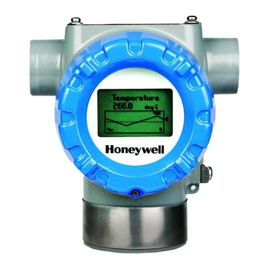
Page 13: Stt850 Smartline Transmitter Name Plate
Electronic Housing (see Figure You can also use the Honeywell MC Toolkit or other third-party hand-held zero to make any adjustments to an STT850 SmartLine Temperature Transmitter. Alternately, certain adjustments can be made through the Experion or Universal Station, if the Transmitter is digitally integrated with a Honeywell Experion or TPS system. -
Page 14: Display Options
1.6 Display Options The STT850 SmartLine Temperature Transmitter has two display options: Basic and Advanced; see Table 2. Table 2 – Available Display Characteristics Basic Display • Suitable for basic process needs • rotation in 90 increments • 2 lines,16 characters •... -
Page 15: Application Design
2 Application Design 2.1 Overview This section discusses the considerations involved with deploying a Honeywell STT850 SmartLine Temperature Transmitter in a process system. The following areas are covered: • Safety • Input and output data • Reliability • Environmental limits •... -
Page 16: Safety Integrity Level (Sil)
2.2.3 Safety Integrity Level (SIL) The STT850 is intended to achieve sufficient integrity against systematic errors by the manufacturer’s design. A Safety Instrumented Function (SIF) designed with this product must not be used at a SIL level higher than the statement, without “prior use” justification by the end user or diverse technology redundancy in the design. -
Page 17: Installation And Startup
3 Installation and Startup 3.1 Installation Site Evaluation Evaluate the site selected for the STT850 SmartLine Transmitter installation with respect to the process system design specifications and Honeywell’s published performance characteristics for your particular model. Some parameters that you may want to include in your site evaluation are: •... -
Page 18: Mounting Stt850 Smartline Temperature Transmitters
Figure 4 – Typical Bracket Mounted Installations 3.4.2 Mounting Dimensions Refer to Honeywell drawing number 50094836 for detailed dimensions of the transmitter assembly. Abbreviated overall dimensions are also shown on the Specification Sheets for the transmitter models. This section assumes that the mounting dimensions have already been taken into account and the mounting area can accommodate the Transmitter. -
Page 19: Wiring A Transmitter
Figure 5 – Pipe Mounting Bracket Secured to a Horizontal or Vertical Pipe 3.5 Wiring a Transmitter 3.5.1 Loop Power Overview The transmitter is designed to operate in a two-wire power/current loop with loop resistance and power supply voltage within the HART operating range shown in Figure 6. -
Page 20: Figure 7 - Transmitter 9-Screw Terminal Board And Grounding Screw
Loop wiring is connected to the Transmitter by simply attaching the positive (+) and negative (–) loop wires to the positive (+) and negative (–) terminals on the Transmitter terminal block in the Electronics Housing shown in Figure 7. Connect the Loop Power wiring shield to earth ground only at the power supply end. -
Page 21: Digital System Integration Information
The positive and negative loop wires are connected to the positive (+) and negative (–) terminals on the terminal block in the Transmitter Electronics Housing. Barriers can be installed per Honeywell’s instructions for Transmitters to be used in intrinsically safe applications. -
Page 22: Grounding And Lightning Protection
42 V DC. Consult the process design system documentation for specifics. 3.5.7 Process Sealing The STT850 SmartLine Temperature Transmitter is CSA-certified as a Dual Seal device in accordance with ANSI/ISA–12.27.01–2003, “Requirements for Process Sealing Between Electrical Systems and Flammable, or Combustible Process Fluids.”... -
Page 23: Input Sensor Wiring
3.5.9 Input Sensor Wiring Connect the input sensors as shown in Figures below: Figure 8 – Thermocouple, mV and Volt Connections o To minimize common noise problems in the application, a strap/jumper should be wired between terminals 6 and 8. For differential T/C operation, a second strap/jumper should be wired between terminals 6 and 7. -
Page 24: Figure 9 - Rtd And Ohm Connections
Figure 9 – RTD and Ohm Connections o Resistance temperature detector (RTD) measurements use the 3 or 4 wire approach. o Dual-input units wired for a 4-wire RTD will automatically disable Input 2. Figure 9 – RTD and Ohm Connections Figure 10- Remote C/J and Mixed Sensors Connections (Not available on DE Models) o For Remote C/J compensation, the first input is a thermocouple type and the second... -
Page 25: Digital Output Wiring
Figure 10– Remote C/J and Mixed Sensors Connections (Not available on DE Models) 3.5.10 Digital Output Wiring The Digital Output is rated at a maximum load of 40 milliamps and 30 Volts. The Digital Output is mutually exclusive with the Second Sensor Input. Figure 11–... -
Page 26: Startup
For best performance, it is recommended that: • Digital Output wires should be in a separate shielded twisted pair cable, do not use the same cable as used for the Loop or the Sensor wires • If using the same power supply to operate both the 4-20mA Loop and the Digital Output, then make the interconnections to the power supply terminals directly at the power supply Figure 12–... -
Page 27: Output Check Procedures
The actual steps in a startup procedure vary based on the type of Transmitter and the measurement application. In general, the procedures in this section are based on using Honeywell MC Toolkit to check the Transmitter input and output under static process conditions, and make adjustments as required initiating full operation with the running process. -
Page 28: Constant Current Source Mode Procedure
3.6.4 Constant Current Source Mode Procedure Figure 13 – Current Loop Test Connections 1. Refer to Figure 12 for test connections. Verify the integrity of electrical components in the output current loop. 2. Establish communication with the Transmitter. For these procedures, the values of components in the current loop are not critical if they support reliable communication between the Transmitter and the Toolkit. -
Page 29: Operation
4 Operation 4.1 Overview This section provides the information and processes involved for both Digitally Enhanced (DE) and HART operation using the 3-button option. 4.2 Three-Button Operation The STT850 optional three-button interface provides a user interface and operation capability without opening the transmitter. -
Page 30: Menu Navigation
Table 4 – Three-Button Option Functions Physical Basic Display Advanced Display Action Button Increment Increment Scroll to previous menu item in an active list. Left Scroll through alphanumeric list to desired character (ex. for entering Tag names or Previous Menu Item Move cursor Up numeric values) Decrement... -
Page 31: Editing A Numeric Value
All numeric entries are clamped at the low or high limit if needed. You can determine the low and high limit for a parameter by selecting either the ▲ or ▼ character while the cursor is positioned over ↵ the left-most digit and press button. -
Page 32: The Advanced Display Menus
4.2.5 The Advanced Display Menus The Advanced Display menus are organized into three levels, as shown by Table 6. There is amenu item at each level that allows the user to return to the previous level. Table 6 – Advanced Display Main Menu Structure Level 1 Level 2 Level 3... -
Page 33: Table 7 -Diagnostics Menu
Diagnostics Menu Table 7 – All Diagnostics menu items are Read Only.Return to the Level 1 menu Active Diags Description FAULT: There is a problem with Sensor FAULT the Sensor Module FAULT: There is a problem with Comm Module the Electronics Module (HART, FAULT... - Page 34 LOW: Supply voltage is below the low specification limit. Supply Voltage HIGH: Supply voltage is above HIGH the high specification limit. OVERTEMP: Temperature Sensor Sensor Module Module temperature is greater Temp OVER TEMP than 85C or less than -40C. OVERTEMP: Electronics Comm Module temperature is greater than 85C or Temp...
-
Page 35: Table 8 -Display Setup Menus
Display Setup Menus Table 8 –Return to the Level 1 menu Press ↵ to enter Adjust the LCD contrast level. Range from 0 to 9. menu selection ↑ and ↓ to select Default: 5 Contrast Set Contrast number. - Page 36 Press ↵ to enter menu selection Display R, K Select the Display Units for ↑ and ↓ to select Units the selected PV. from list. ↵ to enter Press ↵ to enter None menu selection Select the decimal resolution ↑ and ↓ to select Decimal X.XX for the PV.
-
Page 37: Table 9 -Calibration Menus
Calibration Menus Table 9 –Return to the Level 1 menu S1 Cal Lo Pt Calibration low point for Sensor 1 S1 Cal Hi Pt Calibration high point for Sensor 1 Points S 2 Cal Lo Pt Calibration low point for Sensor 2 S2 Cal Hi Pt Calibration high point for Sensor 2 ... -
Page 38
Press ↵ to enter menu 1 Corr Executing this selection resets the Sensor selection Reset Cals 1 and calibrations back to Factory values. Scroll to Reset Cals Press ↵ to initiate
Reset Cal Executing this selection resets the Sensor 2 Corr Reset Cals 1 calibrations back to Factory values. -
Page 39: Table 10 -Transmitter Setup Menus
0.0 to 32.0 seconds Press ↵ to Disabling sets the loop output Disabled and burnout levels to the enter menu Honeywell levels selection NAMUR Output ↑ and ↓ to Enabling sets the loop output Enabled and burnout levels to the select from list ↵... - Page 40 the Loop Enable or disable Critical Diagnostic when Sensor Delta (difference between Excess Delta Enable, Disable Sensor 1 and Sensor 2) exceeds Delta Limit. A Non- Critical Diagnostic occurs if Disabled. Value that will produce a Delta Limit Diagnostic if exceeded by Sensor Delta.
-
Page 41
The limit for the Lower Range Enter LRV Value is the Lower Range Enter LRV ###. ## Limit (LRL) of the selected Sensor ID. The limit for the Upper Range Enter URV Value is the Upper Range Enter URV ###. -
Page 42
Sensor 1 mV, TC, RTD, Type Sensor 1 ID Sensor ID for Input mV, TC, RTD, Sensor 2 Type Sensor 2 ID Sensor ID for Input RTD 1 Type 2-Wire, 3-Wire, 4- Wire Sensor User entered value for the Setup RTD 1 Lead Resistance of Input... -
Page 43: Table 11 -Information Menus
Comm Module protocols The communications protocol of the transmitter: • HART: HART protocol Read Protocol • Only DE: Honeywell DE protocol • FF: Foundation FieldbusRead Firmware Version The firmware version of the Sensor Module Only Read Model Key... -
Page 44: The Basic Display Menu
Setup\Parameters\Units) Read LRL1 The Lower Range Limit of the Input 1 Sensor Only Read URL1 The Upper Range Limit of the Input 1 Sensor Only Read LRL2 The Lower Range Limit of the Input 2 Sensor Only Read URL2 The Upper Range Limit of the Input 2 Sensor Only 4.2.6 The Basic Display Menu The Basic Display Menu is implemented as one long single-level menu and will “wrap around”... - Page 45 Select Input number to configure, Select Input 1 - 8 referred to as "n" in subsequent menu items Sensor n Type mV, TC, RTD, Ohm Select Sensor Type Sensor n ID Sensor Identifier Select Sensor ID for Input n for selected Sensor Type RTD n Type 2-Wire, 3-Wire, 4-Wire...
- Page 46 Executing this selection corrects Do Sens n Cal Lo Confirm the Cal Low Point based on the input measurement Executing this selection corrects Do Sens n Cal Hi Confirm the Cal High Point based on the input measurement Executing this selection Resets the Reset Sens n Cal Confirm LRV, and URV Corrects back to...
- Page 47 Hysteresis ###.## Hysteresis value relative to the ↑ and ↓ to select ↵ to enter MRV for the transition of Loop Control between Sensors when digit. Loop Ctrl Mode is Split-Range Press ↵ to enter Break Detect Enable, Disable Enable or disable detection of Input wire break For Redundant Loop Control menu selection...
- Page 48 32.0 seconds Press ↵ to enter menu selection Disabling sets the loop output and Enabled ↑ and ↓ to NAMUR Output burnout levels to the Honeywell Disabled levels select from list ↵ to enter Press ↵ to enter menu selection ↑...
-
Page 49: Selecting A New Setting From A List Of Choices
Press ↵ This selection allows the user to enter the date a transmitter is to enter installed. menu The Install Date is entered in selection sequence of Day, Month, and ↑ and ↓ to select Year, followed by the new date and the prompt Write Date to Install Date DD MM YYYY... -
Page 50: Three Button Operation With No Display Installed
4.3 Three Button Operation with no Display Installed When there is no Display installed, the buttons can be used to perform a Zero or Span adjustment of the Transmitter. Caution should be taken to insure these adjustments are only made when the correct input values are applied. -
Page 51: Changing The Default Failsafe Direction
4.4 Changing the Default Failsafe Direction Transmitters are shipped with a default failsafe direction of upscale. This means that the Transmitter output will set the current output to upscale failsafe (maximum output) upon detection of a critical status. You can change the direction from upscale failsafe to downscale failsafe (minimum output) by moving the top jumper located in the Electronics module. -
Page 52: Figure 15 - Locating The Failsafe And Write Protect Jumpers
Figure 15 – Locating the Failsafe and Write Protect Jumpers Table 13 – Hart and DE Failsafe and Write Protect Jumpers Jumper Description Arrangements Failsafe = UP (High) Write Protect = OFF (Not Protected) Failsafe = DOWN (Low) Write Protect = OFF (Not Protected) Failsafe = UP (High) Write Protect = ON (Protected) Failsafe = Down (Low) -
Page 53: Table 14 - Fieldbus Simulation And Write Protect Jumpers
Table 14 – Fieldbus Simulation and Write Protect Jumpers Image Description Fieldbus Simulation Mode = OFF Write Protect = OFF (Not Protected) Fieldbus Simulation Mode = OFF Write Protect = ON (Protected) Fieldbus SIM Mode = ON Write Protect = OFF (Not Protected) 1. -
Page 54: Monitoring The Basic And Advanced Displays
4.5 Monitoring the Basic and Advanced Displays This section describes the information shown on the operator screens of the Advanced and Basic Displays. 4.5.1 Basic Display Figure 15 illustrates the Basic Display format with Process Variable (PV). • The PV value is user-configurable. This field has 7 characters. The maximum allowable numeric value is 9999999 or -999999. -
Page 55: Figure 17 - Advanced Display Formats With The Process Variable
Figure 17 – Advanced Display Formats with the Process Variable Table 15 – Advanced Displays with PV Format Display Indications Display Indicator What It Means Diagnostic / Diagnostic condition present Maintenance This indicator is displayed any time a diagnostic is present in the transmitter, either Critical or Non-Critical. -
Page 56: Button Operation During Monitoring
PV Status: Good The transmitter is operating normally The transmitter has detected a fault condition. The PV Status field will flash when this condition is present and the PV Value will be displayed on a black background as shown below: Uncertain (this status is only available for FF transmitters) The PV Value is outside of normal limits. -
Page 57: Maintenance
Replacement of damaged parts such as the Electronics Modules. 5.2 Preventive Maintenance Practices and Schedules The STT850 SmartLine Transmitter does not require any specific maintenance at regularly scheduled intervals. Maintenance of the STT850 is limited to ensuring that connections, seals and mounting are tight and secure. - Page 58 1. Turn OFF Transmitter power (Power removal is only required in accordance with area safety approvals. Power removal is only required in Class 1 Div 1 Explosionproof and Class 1 Div 2 environments). • When removing the Communications Module with power applied, the loop will go to 0V.
- Page 59 (Steps 13 - 16 required for Field Upgrades Only) 13. Loosen the End Cap locking screw and unscrew the End Cap from the Field Wiring side of the transmitter housing. 14. Select the proper Communication/External Configuration upgrade kit label from the label strip provided and adhere to the inside of the Field Wiring compartment End Cap.
- Page 60 This page is left blank intentionally. Page 50 STT850 Temperature Transmitter User’s Manual Revision 1...
-
Page 61: Calibration
For a Transmitter operating in analog mode, you must calibrate its output signal measurement range using any compatible hand-held communicator or a local display. One calibration option is to use the Honeywell Smart Field Communicator (SFC). Refer to the Smart Field Communicator Operating Guide, 34-ST-11-14 for calibration procedures. - Page 62 This page is left blank intentionally Page 52 STT850 Temperature Transmitter User’s Manual Revision 1...
-
Page 63: Troubleshooting
However, this section covers the diagnostic messages that indicate critical conditions. Other than the critical conditions, additional detail is not provided. If you require assistance, contact your distributor or Honeywell Technical Support. All other messages are covered by the MC Toolkit Users’ Manual. 7.2 Critical Diagnostics Screens... -
Page 64: Fault Conditions And Recommended Corrective Actions
7.2.1 Fault Conditions and Recommended Corrective Actions Table 16 – Fault Conditions and Recommended Corrective Actions. Recommended Corrective Condtion Analysis Action Electronics Module Use a HART, DE, or FF Cycle power to the transmitter. Fault. communicator to read the detailed If the problem continues to occur A critical failure has status information from the... -
Page 65: Parts List
8 Parts List 8.1 Overview Individually saleable parts for the various Transmitter models are listed in this section. Some parts are illustrated for identification. Parts are identified and listed in the corresponding tables as follows: • Individually saleable parts are indicated in each figure by key number callout. •... -
Page 66: Figure 20 - Pipe And Wall Bracket Parts
100- 1-10 Part Number Description Figure No. 1000 Units Units Units 50086421-507 FieldBus Temperature/Terminal Block Assy Without Lightning Protection, Single Input 50086421-508 FieldBus Temperature/Terminal Block Assy Without Lightning Protection, Dual InputFieldBus Figure 22 50086421-509 Temperature/Terminal Block Assy With Lightning Protection,Single Input 50086421-510 FieldBus Temperature/Terminal Block Assy With Lightning Protection, Dual Input... -
Page 67: Figure 21 - Electronic Housing, Display End
Figure 21 – Electronic Housing, Display End Table 19 – Transmitter Major Assemblies (Refer to Figure Figure Quantity Part Number Description Per Unit 50049858-501 End Cap (Aluminum) 50049858-521 End Cap (Stainless Steel) 50049832-501 End Cap, Display (Aluminum) 50049832-521 End Cap, Display (Stainless Steel) 50086421-501 HART/DE Temperature/Terminal Block Assy Without Lightning Protection, Single Input... -
Page 68: Figure 22 - Electronic Housing, Terminal Block End
50086423--501 HART Electronics Module Assembly (PWA) without Reed sensor 50086423--502 HART Electronics Module Assembly (PWA) with Reed sensor 50086423--503 DE Electronics Module Assembly (PWA) without Reed sensor 50086423--504 DE Electronics Module Assembly (PWA) with Reed sensor 50086423--507 FF Electronics Module Assembly (PWA) without Reed sensor 50086423--508 FF Electronics Module Assembly (PWA) with Reed sensor External Zero, Span &... -
Page 69: Appendix A. Product Certifications
Appendix A. PRODUCT CERTIFICATIONS A1. Safety Instrumented Systems (SIS) Installations For Safety Certified Installations, please refer to STT850 Safety Manual 34-TT-25-05 for installation procedure and system requirements. A2. European Directive Information (CE Mark) Revision 1 STT850 Temperature Transmitter User’s Manual Page 59... - Page 70 Page 60 STT850 Temperature Transmitter User’s Manual Revision 1...
- Page 71 Revision 1 STT850 Temperature Transmitter User’s Manual Page 61...
- Page 72 Page 62 STT850 Temperature Transmitter User’s Manual Revision 1...
- Page 73 A3. Hazardous Locations Certifications COMM. FIELD AMBIENT AGENCY TYPE OF PROTECTION OPTION PARAMETERS TEMP (Ta) Explosion proof: Class I, Division 1, Groups A, B, C, D; Dust Ignition Proof: 4-20 mA / Note 1 -50ºC to 85ºC Class II, III, Division 1, Groups E, F, G; T4 DE/ HART Class 1, Zone 1/2, AEx d IIC T4 Class 2, Zone 21, AEx tb IIIC T 95...
- Page 74 FM12ATEX0029X Flameproof: Note 1 -50 ºC to 85ºC II 1/2 G Ex d IIC T4 II 2 D Ex tb IIIC T 85 C IP 66 Enclosure: IP66/ IP67 ATEX- FM Standards: EN 60079-0: 2011 EN 60079-1 : 2007 EN 60079-31 : 2009 EN 60079-26 : 2007 EN 60529 : 2000 + A1 Sira12ATEX2233X...
- Page 75 Flameproof: T5 Ta = –50 ºC Ex d IIC Ga/Gb T4 Note 1 to 85ºC Ex tb IIIC Db T 85oC IP 66 Intrinsically Safe: T4 Ta = –50 ºC INMETRO 4-20 mA / DE/ Ex ia IIC Ga T4 Note 2 to 70ºC (Brazil)
-
Page 76: Warnings And Cautions
A4. Marking ATEX Directive General: The following information is provided as part of the labeling of the transmitter: • Name and Address of the manufacturer • Notified Body identification: DEKRA Quality B.V., Arnhem, the Netherlands • For complete model number, see the Model Selection Guide for the particular model of Temperature Transmitter. - Page 77 A.5 Conditions of Use” for Ex Equipment”, Hazardous Location Equipment or “Schedule of Limitations” Consult the manufacturer for dimensional information on the flameproof joints for repair. Painted surface of the STT850 may store electrostatic charge and become a source of ignition in applications with a low relative humidity less than approximately30% relative humidity where the painted surface is relatively free of surface contamination such as dirt, dust or oil.
- Page 78 A.6 Control Drawing Page 68 STT850 Temperature Transmitter User’s Manual Revision 1...
- Page 79 Revision 1 STT850 Temperature Transmitter User’s Manual Page 69...
- Page 80 Page 70 STT850 Temperature Transmitter User’s Manual Revision 1...
-
Page 81: Glossary
Glossary American Wire Gauge Digital Enhanced Communications Mode Electromagnetic Interference Field Termination Assembly Hertz Lower Range Limit Lower Range Value mAdc Milliamperes Direct Current Millivolts Newton meters Non-Volatile Memory Process Manger Process Variable Printed Wiring Assembly Radio Frequency Interference Resistance Temperature Detector Smart Field Communicator STIM Temperature Transmitter Interface Module... - Page 82 Optional 3-Button Assembly ....... 4 Physical Characteristics ..........1 Parts List ........... 55 Glossary ........... 71 Patent Notice ..........iv Honeywell MC Toolkit ......... 7 References ..........iv Release Information ........iii Safety ............5 Page 72 STT850 Temperature Transmitter User’s Manual...
- Page 83 Accuracy ..............5 Span Adjustments ............ 40 Diagnosis Messages ........... 5 Zero Adjustments ............ 40 Safety Integrity Level ..........6 Three-Button Operation ......19 Safety Certification ........3 Advanced Display Entries ........22 Startup ............. 16 Basic Display menu ..........34 Data Entry ..............
- Page 84 Phone: +(822) 799 6114 Fax: +(822) 792 9015 For more information To learn more about SmartLine Transmitters, visit www.honeywellprocess.com Or contact your Honeywell Account Manager Process Solutions Honeywell 1250 W Sam Houston Pkwy S Houston, TX 77042 Honeywell Control Systems Ltd...