Honeywell STT700 SmartLine User Manual
Temperature transmitter
Hide thumbs
Also See for STT700 SmartLine:
- Quick start installation manual (14 pages) ,
- User manual (114 pages) ,
- Safety manual (16 pages)
Table of Contents
Quick Links
See also:
User Manual
Table of Contents
Troubleshooting

Related Manuals for Honeywell STT700 SmartLine


Summary of Contents for Honeywell STT700 SmartLine
- Page 1 STT700 SmartLine Temperature Transmitter User’s Manual 34-TT-25-17 Revision 2 February 2018 Honeywell Process Solutions...
- Page 2 In no event is Honeywell liable to anyone for any indirect, special, or consequential damages. The information and specifications in this document are subject to change without notice.
- Page 3 Experion Knowledge Builder. For Honeywell’s TotalPlant Solutions (TPS), you will need to supplement the information in this document with the data in the PM/APM SmartLine Transmitter Integration Manual, which is supplied with the TDC 3000 book set. (TPS is the evolution of the TDC 3000).
- Page 4 Smart Field Communicator Model STS 103 Operating Guide, Document # 34-ST-11-14 (for use with STT700 DE only) Patent Notice The Honeywell STT700 SmartLine Temperature Transmitter family is covered by one or more of the following U. S. Patents: 5,485,753; 5,811,690; 6,041,659; 6,055,633; 7,786,878; 8,073,098; and other patents pending.
- Page 5 Symbol Descriptions and Definitions The symbols identified and defined in the following table may appear in this document. Symbol Definition ATTENTION: Identifies information that requires special consideration. TIP: Identifies advice or hints for the user, often in terms of performing a task.
- Page 6 Symbol Description ® The Factory Mutual Approval mark means the equipment has been rigorously tested and certified to be reliable. The Canadian Standards mark means the equipment has been tested and meets applicable standards for safety and/or performance. The Ex mark means the equipment complies with the requirements of the European standards that are harmonized with the 94/9/EC Directive (ATEX Directive, named after the French "ATmosphere EXplosible").
-
Page 7: Table Of Contents
Features and Options ......................1 1.2.1. Physical Characteristics ....................2 1.2.2. Functional Characteristics ....................3 1.3. STT700 SmartLine transmitter nameplate ................3 1.4. Safety Certification Information ..................... 4 1.5. Transmitter Adjustments ......................4 EU Meter Option – HART only ..................... 4 1.6. - Page 8 Calibration ............................ 35 7.1. Recommendations for transmitter Calibration ..............35 7.2. Calibration Procedures ......................35 Appendix A. PRODUCT CERTIFICATIONS ..................36 Glossary ............................... 51 List of Figures Figure 1 – STT700 HART Transmitter module ..................2 Figure 2- STT700 DE Transmitter module .................... 2 Figure 3 –...
-
Page 9: Introduction
This section is an introduction to the physical and functional characteristics of Honeywell’s STT700 SmartLine Temperature Transmitter. 1.2. Features and Options The STT700 SmartLine Temperature Transmitter is available in a variety of models for measuring Thermocouples, RTD, Millivolts, and ohm sensor types. Table 1 lists the protocols, Human-Machine Interface (HMI), materials, approvals, and mounting bracket options for the STT700. -
Page 10: Physical Characteristics
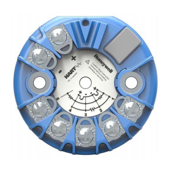
1.2.1. Physical Characteristics As shown in Figure 1 Figure 2, the STT700 is packaged in a single module. The elements in this module are connected to the process sensors, measure the process variables, respond to setup commands and execute the software and protocol for the different temperature measurement types. Figure 1 –... -
Page 11: Functional Characteristics
(PV). Available output communication protocols include 4 to 20mA, Honeywell Digitally Enhanced (DE) and HART protocols. In addition, a Honeywell Multi-Communication (MC) Toolkit (not supplied with the transmitter) can facilitate setup and adjustment procedures in the case of HART and DE. Certain adjustments can be made through an Experion Station or a Universal Station if the transmitter is digitally integrated with Honeywell’s Experion or TPS/TDC 3000 control system for HART and DE transmitters. -
Page 12: Safety Certification Information
1.5. Transmitter Adjustments For HART and DE you can use the Honeywell MC Toolkit or other third-party hand-held (for HART) to make any adjustments to an STT700 SmartLine Temperature Transmitter. Any HART 7.0 compliant PC host like Honeywell FDM can be used to configure the device. -
Page 13: Application Design
STT700 transmitter. Refer to the Troubleshooting section for further details. Table 3 show specific diagnostics to the transmitter, exclusive of those associated with HART and DE protocols. HART and DE diagnostic messages are listed and described in the STT700 SmartLine Temperature Transmitter HART/DE Option User Manual, document number 34-TT-25-18. -
Page 14: Table 3 - Stt700 Diagnostic Messages
Table 3 – STT700 Diagnostic Messages Description Details Critical Diagnostics (Failure Conditions) Elec. Mod. Diag Failure Action: Reset the device. If the problem persists Diagnostics failure (like replace the electronics module Note: Select ROM / RAM corrupt “Device Status - Additional Status” to see which etc.) of these conditions are set. - Page 15 Sensor1 excess LRV Applied Input 1 value and This non critical flag will be set when correct measured value differ by difference between applied Input 1 LRV value more than 1.5% span at and measured value exceeds 1.5% of span. low calibration point Perform Reset correct.
- Page 16 Input2 Out Of Range Input 2 temperature is greater than Sensor 2 URL or less than Sensor 2 LRL. Measured value of Sensor2 is out of range Set when the input at second sensor is either under range or over range Watchdog reset Watchdog has reset (it may be due to FW failure or HW...
-
Page 17: Installation And Startup
3.1. Installation Site Evaluation Evaluate the site selected for the STT700 SmartLine transmitter installation with respect to the process system design specifications and Honeywell’s published performance characteristics for your particular model and sensor selection. Some parameters that you may want to include in your site evaluation are: ... -
Page 18: Mounting
3.3. Mounting 3.3.1. DIN Rail Mounting If the STT700 is to be installed on DIN rail option then the main considerations are electrical connections and mechanical fixing. Electrical connections are identical to the bench test instructions except that thermocouple wire is likely to be used with thermocouples. Mechanical fixing of the module is by means of the snap-in DIN rail clips which are screwed to the bottom lugs of the module. -
Page 19: Mounting Module In Housing
3.3.2. Mounting Module in Housing The STT700 module can be installed in a variety of housings suitable for field mounting (2” or 50mm pipe mount), direct head mounting, or wall mounting. Ensure that the installation location is suitable for reliable transmitter operation (e.g. for high temperature applications, a thermowell extension is recommended to minimize failure rates due to high ambient temperatures near the transmitter). -
Page 20: Figure 7: Pipe Mounting Dimensions
Field Mount Housing with and Field Mount Housing with Meter Field Mount Housing without Meter without Meter Figure 7: Pipe Mounting Dimensions Table 5 - Dimension table for use with Figure 6 and Figure 7 Dimensions Aluminum (field mount housing) Without integral meter 70 mm [2.76 inch] 120,8 mm [4.76 inch]... -
Page 21: Uninstalling/Installing Eu Meter From Housing
3.3.3. Uninstalling/Installing EU Meter from Housing EU Meter: 1. Remove the EU METER from the mounting bracket. 2. Unfasten the 2 mounting screws. 3. Remove the bracket. To put the EU meter back follow the above sequence in the reverse order. STT700 Temperature Transmitter User’s Manual Revision 2 Page 13... - Page 22 Housing Cover and O Ring: 1. Review O-ring condition & replace, if damaged. New O-ring can be ordered from spare parts list. 2. Apply O-ring lubricant to the end cap O-ring. Relax O-ring twists, if any. 3. Assemble housing cover with sufficient torque for securing against IP. STT700 Temperature Transmitter User’s Manual Page 14 Revision 2...
-
Page 23: Spring Loading
3.3.4. Spring Loading Figure 8: Spring Loading and Sensor Assembly Spring loading is available worldwide with direct head mounting. In North America, the spring loading is typically included in the sensor/thermowell assembly and is available with all housings. For non-North American spring loading as shown in Figure 8, simply include the springs under the 33 mm pitch mounting screws, pass the screws through the module and sensor mounting plate and snap... -
Page 24: Wiring A Transmitter
3.4. Wiring a transmitter 3.4.1. Loop Power Overview The transmitter is designed to operate in a two-wire power/current loop with loop resistance and power supply voltage within the HART or DE operating range shown in Figure 9 and Figure Figure 9 – STT700 with HART Transmitter Operating Ranges Figure 10–... -
Page 25: Figure 11 -Stt700 Module Terminal Connections
Loop wiring is connected to the transmitter by simply attaching the positive (+) and negative (–) loop wires to the positive (+) and negative (–) terminals on the transmitter module terminal block. Route the wires through the pre-moded channels on top of the terminal module. Connect the loop power wiring shield to Earth Ground only at the power supply end. -
Page 26: Digital System Integration Information
The positive and negative loop wires are connected to the positive (+) and negative (–) terminals on the STT700. Barriers can be installed per Honeywell’s instructions for transmitters to be used in intrinsically safe applications. Note: Problems detected as non-critical diagnostics may affect performance without driving the analog output to the programmed burnout level (for HART only). -
Page 27: Grounding And Lightning Protection
3.4.4. Grounding and Lightning Protection Connect a wire from the mounting screws to Earth Ground to make the protection effective. Use size 14 AWG or 2.0mm bare or green covered wire for this connection. For ungrounded thermocouple, mV, RTD or ohm inputs, connect the input wiring shield(s) to the same Earth Ground connection. -
Page 28: Input Sensor Wiring
3.4.5. Input Sensor Wiring Connect the input sensors as shown in Figures below for RTD, thermocouple, mV and ohm connections. Figure 12 – HART/DE Input Wiring Diagram for single sensor connection The single sensor connections can also be used on a dual input transmitter when a second input is not required. -
Page 29: Lightning Protector
It mounts on the top of the STT700 transmitter module, providing easy field wiring and also protection for the EU meter if used. The compact mounting allows the use of a variety of housings including the Honeywell explosion proof field mount housing. -
Page 30: Figure 15 - Installation Without Eu Meter
3.4.6.1. Installation If an EU meter is used, remove the shunt on the Lightning Protector. In all other cases, the shunt must be present. Remove the cover/cap of the housing (if applicable). The device fits on the top of the transmitter module terminal block and the transmitter output screws (+ and -) fix mechanically the device. -
Page 31: Figure 16 - Installation With Eu Meter
Figure 16 – Installation with EU Meter 3.4.6.2. Maintenance The unit is designed to give a long service life under normal industrial conditions. However, if exposed to a large number of high energy transients beyond the capability of the unit, the lightning protector may fail. -
Page 32: Startup
The actual steps in a startup procedure vary based on the type of transmitter and the measurement application. In general, the procedures in this section are based on using Honeywell MC Toolkit, with a HART or DE variant, to check the transmitter input and output under static process conditions, and make adjustments as required initiating full operation with the running process. -
Page 33: Constant Current Source Mode Procedure
4.1.4. Constant Current Source Mode Procedure Figure 17 – Current Loop Test Connections 1. Refer to Figure 17 for test connections. Verify the integrity of electrical components in the output current loop. 2. Establish communication with the transmitter. For these procedures, the values of components in the current loop are not critical if they support reliable communication between the transmitter and the MC Toolkit. -
Page 34: Operation
5. Operation 5.1. Overview The Operations section describes the internal operation of the STT700 transmitter and the operations of the Smart Field Communicator and the HART communicator with the STT700. If an EU Meter is installed, see the Engineering Unit Meter User Guide 34-ST-25-18 for additional information on operations. -
Page 35: Hart Communicator Model 375, 475 Or Mc Toolkit Fdc For Hart 7 Models
5.2.2. HART Communicator Model 375, 475 or MC Toolkit FDC for HART 7 Models Connect the HART communicator by attaching the leads in parallel with the input (24V) terminals of the device. HART communication consists of a high frequency carrier superimposed onto the 4-20 mA signal. - Page 36 Advanced Diagnostics Read Install Date Write Install Date Read Calibration Date and Time Write Correct LRV Date and Time Write Correct URV Date and Time Read Time in service value Read first set of Error log data ...
-
Page 37: Maintenance
6. Maintenance 6.1. Overview Maintenance of this transmitter is limited to ensuring that connections, seals and mounting hardware are tight and secure. There are no moving parts or adjustments, thus, the only reason to open the housing (where supplied) is to inspect for corrosion or conductive dust entry which could later affect reliable operation. - Page 38 SYMPTOM SFC MESSAGE/ POSSIBLE CAUSE CURE DISPLAY Incorrect operating voltage. line resistance is not excessive. "STATUS CHECK = O.K." Unstable onscale Bad sensor wire Check connection and wiring input since any identified connection. for intermittent connections. problem would give upscale or downscale fail-safe.
-
Page 39: Troubleshooting With Hart Communicator
6.3.2. Troubleshooting with HART communicator Troubleshooting the STT700 HART transmitter loop is greatly simplified by connecting a HART Communicator in the termination area near the receiving instrument. Also connect a digital volt meter (DVM), at the termination area for the receiving instrument, to confirm a similar signal is coming from the field and power is available on the two wires of the 4-20 mA loop. -
Page 40: Recommended Parts
6.4. Recommended Parts GENERAL DESCRIPTION: Reference STT700 transmitter module device Order from the Model Selection Guide to include options as required. METERS Replacement EU meter 51451985-501 Meter mounting bracket kit 46188056-502 HEAD MOUNT HOUSINGS (Cable/Conduit entry noted. All have ½” NPT sensor entry) Aluminum head mount housing (M20) 46188452-501 Aluminum head mount housing (1/2"NPT) - Page 41 STT700 Temperature Transmitter User’s Manual Revision 2 Page 33...
-
Page 42: Wiring And Installation Drawings
MISCELLANEOUS PARTS (TBC) Adaptor plate to install module in field mount housing 46188423-501 Spring loading mounting set 46188416-501 51156364-501 DIN rail mounting (top hat/"" or "G" rail) Carbon steel mounting bracket for 2" pipe 30755905-501 (for use with field mount housing) Stainless steel mounting bracket for 2"... -
Page 43: Calibration
For a transmitter operating in analog mode, you must calibrate its output signal measurement range using any compatible hand-held communicator.. One calibration option is to use the Honeywell MC Toolkit (MCT). Refer to the MC Toolkit User Manual, MCT404, Document # 34-ST-25-50 Calibration information and procedures for a transmitter operating in the HART/DE mode are provided in the STT700 Series HART/DE Option User’s manual, document number 34-TT-25-18,... -
Page 44: Appendix A. Product Certifications
Appendix A. PRODUCT CERTIFICATIONS A1. Safety Instrumented Systems (SIS) Installations For Safety Certified Installations, please refer to STT700 Safety Manual 34-TT-25-05 for installation procedure and system requirements. A2. European Directive Information (EU) STT700 Temperature Transmitter User’s Manual Page 36 Revision 1... - Page 45 STT700 Temperature Transmitter User’s Manual Revision 2 Page 37...
- Page 46 STT700 Temperature Transmitter User’s Manual Page 38 Revision 1...
- Page 47 STT700 Temperature Transmitter User’s Manual Revision 2 Page 39...
- Page 48 STT700 Temperature Transmitter User’s Manual Page 40 Revision 1...
- Page 49 A3. China RoHS China RoHS compliance information is located here: (Pending) https://www.honeywellprocess.com/library/support/Public/Documents/50136434.pdf STT700 Temperature Transmitter User’s Manual Revision 2 Page 41...
- Page 50 A4. Hazardous Locations Certifications AGENCY TYPE OF PROTECTION Electrical Ambient CODE Parameters Temperature Intrinsically Safe T6: -40 C to +40 Certificate: FM17US0112X Note 2 T5: -40 C to +55 Class I Division 1, Groups A, B, C, D; T6 .. T4 T4: -40 C to +70 Class I Zone 0 AEx ia IIC T6..
- Page 51 Explosion proof Certificate: 70113941 Class I, Division 1, Groups A, B, C, D; T6.. T5 Ex db IIC T6.. T5 Gb T6: -40 C to +65 Class 1, Zone 1, AEx db IIC T6.. T5 Gb Note 1 C/T5: -40 C to Dust-Ignition Proof: Class II, III, Division 1, Groups E, F, G;...
- Page 52 Intrinsically Safe T6: -40 C to +40 Note 2 Certificate: SIRA 17ATE2162X T5: -40 C to +55 II 1 G Ex ia IIC T6..T4 Ga T4: -40 C to +70 Non Sparking and Zone 2 Intrinsically Safe ATEX T6: -40 C to +40 Certificate: SIRA 17ATE4161X Note 1...
- Page 53 A5. Marking ATEX Directive General: The following information is provided as part of the labeling of the transmitter: • Name and Address of the manufacturer • Notified Body identification: DEKRA Quality B.V., Arnhem, the Netherlands • For complete model number, see the Model Selection Guide for the particular model of temperature transmitter.
- Page 54 A.6 Conditions of Use” for Ex Equipment”, Hazardous Location Equipment or “Schedule of Limitations”: The installer shall provide transient over-voltage protection external to the equipment such that the voltage at the supply terminal of the equipment does not exceed 140% of the voltage rating of the equipment.
- Page 55 A.6 Control Drawing STT700 Temperature Transmitter User’s Manual Revision 2 Page 47...
- Page 56 STT700 Temperature Transmitter User’s Manual Page 48 Revision 1...
- Page 57 STT700 Temperature Transmitter User’s Manual Revision 2 Page 49...
- Page 58 STT700 Temperature Transmitter User’s Manual Page 50 Revision 1...
-
Page 59: Glossary
Glossary American Wire Gauge Cold Junction Callendar-Van Dusen is an equation that describe the relationship between resistance (R) and temperature (t) of platinum resistance thermometers (RTD) Device Description Digital Enhanced Communications Mode Device Type Manager Electromagnetic Interference EEPROM Electrically Erasable Programmable Read Only Memory Field Device Manager Field Termination Assembly HART... - Page 60 Thermocouple Upper Range Limit Upper Range Value Universal Station Volts Alternating Current Volts Direct Current WRITE AS ONE (grouping of parameters for editing, for example you can edit PV URV and PV LRV in one shot if URV LRV is provided under wao list) STT700 Temperature Transmitter User’s Manual Page 52...
- Page 61 Safety Safety Integrity Level ..........5 Safety Certification ........4 Startup ............. 24 Honeywell MC Toolkit ......... 9 Constant Current Source Mode Procedure ..... 25 Output Check Procedures ........24 Support and Contact Information ....iv Symbol Descriptions and Definitions ... v Installation and Startup ......
- Page 62 Phone: +(822) 799 6114 Fax: +(822) 792 9015 For more information To learn more about SmartLine transmitters, visit www.honeywellprocess.com Or contact your Honeywell Account Manager Process Solutions Honeywell 1250 W Sam Houston Pkwy S Houston, TX 77042 Honeywell Control Systems Ltd...