Allen-Bradley ControlLogix User Manual
Controllogix data highway plus/remote i/o communication interface module
Hide thumbs
Also See for ControlLogix:
- Reference manual (497 pages) ,
- User manual (203 pages) ,
- Installation instructions manual (16 pages)
Table of Contents
Troubleshooting

Related Manuals for Allen-Bradley ControlLogix


Summary of Contents for Allen-Bradley ControlLogix
- Page 1 Allen-Bradley User ControlLogix Data Highway Plus/ Manual Remote I/O Communication Interface Module...
- Page 2 Ethernet is a registered trademark of Digital Equipment Corporation, Intel and Xerox Corporation. Microsoft is a registered trademark of Microsoft Corporation. Windows, Windows 95 and Windows NT are trademarks of Microsoft Corporation. ControlLogix and Data Highway Plus are trademarks of the Allen-Bradley Company, Inc.
-
Page 3: About This User Manual
This manual describes how to understand, configure and troubleshoot your ControlLogix Data Highway Plus/Remote I/O communication interface module. For installation information, refer to the ControlLogix Data Highway Plus Communication Interface Module Installation Instructions, publication 1756-5.4. Publication 1756-6.5.14 - August 1998... - Page 4 About This User Manual Conventions and Related Terms This manual uses the following conventions: This icon: Calls attention to: helpful, time-saving information Example an example For more information . . . additional information in the publication referenced Publication 1756-6.5.14 - August 1998...
- Page 5 LED indicator link a unique network module address a six-bit number used to uniquely identify any module on the local and extended ControlLogix backplane PCCC programmable controller communications commands rack a physical and logical collection of application modules sharing a common power supply and backplane for module to module...
- Page 6 About This User Manual Related Products and The following table lists related ControlLogix products and documentation: Documentation Catalog Publication Document title: number: number: 1756-DHRIO Data Highway Plus Communication Interface Module 1756-5.4 Installation Instructions 1756-GTWY ControlLogix Gateway Configuration Tool Quick Start 1756-10.2...
-
Page 7: Table Of Contents
Table of Contents ControlLogix Data Highway Plus/ Chapter 1 Remote I/O Communication What the Module Does ......1-1 Interface Module Routing Limitations . - Page 8 Two 1756-DHRIO Modules With One ControlLogix Chassis ......5-5 Set the Module Switches ....5-6 Set-Up a Routing Table for the First 1756-DHRIO Module .
- Page 9 Over ControlNet and DH+ With Multiple ControlLogix Chassis ......7-9 Set the Module Switches ....7-10 Set-Up a Routing Table for the 1756-DHRIO Module .
- Page 10 toc–iv Table of Contents Logix5550 to Logix5550 Chapter 8 Messaging CIP Messaging Between a Logix5550 and a Logix5550 Over One Link ....8-2 Set the Module Switches .
- Page 11 Table of Contents toc–v Inhibiting an RIO Connector Adapter ... . 10-10 Increased Remote I/O System Throughput ..10-11 Sending Block Transfer Data ....10-12 Block Transfer Notification .
- Page 12 toc–vi Table of Contents Chapter Summary and What’s Next ... . . 12-15 Troubleshooting Chapter 13 Checking Power Supply and Module Status ..13-1 Troubleshooting the Power Supply .
-
Page 13: What The Module Does
Chapter ControlLogix Data Highway Plus/Remote I/O Communication Interface Module What This Chapter Contains This chapter describes the module and what you must know and do before you begin to use it. The following table describes what this chapter contains and its location. -
Page 14: Dh+ And Cip Messaging
ControlLogix Data Highway Plus/Remote I/O Communication Interface Module DH+ and CIP Messaging The 1756-DHRIO module allows an information exchange between devices, such as PLCs, Logix5550 processors in ControlLogix chassis, and SLCs. With the 1756-DHRIO module, you may exchange information in any of the following scenarios: •... -
Page 15: Remote I/O
ControlLogix Data Highway Plus/Remote I/O Communication Interface Module Remote I/O When a channel on the module is configured for Remote I/O, the module will act as a scanner for the RIO network. The Logix5550 controller (1756-L1) communicates to the module’s RIO scanner to send and receive the I/O on the RIO network. -
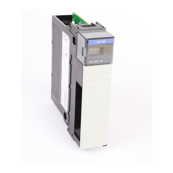
Page 16: Module Features
ControlLogix Data Highway Plus/Remote I/O Communication Interface Module Module Features Use the following illustration to identify the external features of the Data Highway Plus/RIO module. Network Type switches (behind cover) Alphanumeric status indicator Wiring Channel and label module status Backplane... -
Page 17: Setting Switches
ControlLogix Data Highway Plus/Remote I/O Communication Interface Module Setting Switches Before installing the module, you must set the network type switches for DH+ or RIO, depending on your application. For a channel configured as DH+, you must also select a node address within the range of 00-77. -
Page 18: Alphanumeric Indicators
ControlLogix Data Highway Plus/Remote I/O Communication Interface Module Alphanumeric Indicators At module power-up, the alphanumeric indicator illuminates and cycles through a sequence of power-up messages. Included in the sequence is a scrolling display of the series letter, two digits of the firmware major revision, a dot, and two digits of the firmware minor revision. -
Page 19: Low Voltage Directive
Programmable Controllers, Part 2 - Equipment Requirements and Tests. For specific information required by EN 61131-2, see the appropriate sections in this publication, as well as the following Allen-Bradley publications: • Industrial Automation Wiring and Grounding Guidelines For Noise Immunity, publication 1770-4.1 •... -
Page 20: Removal And Insertion Under Power
ControlLogix Data Highway Plus/Remote I/O Communication Interface Module Removal and Insertion Under This module is designed to be installed or removed while chassis power is applied. Power ATTENTION: When you insert or remove a module while backplane power is on, an electrical arc may occur. -
Page 21: What Is Data Highway Plus
Chapter Basics of Using Data Highway Plus What This Chapter Contains This chapter describes the basics of Data Highway Plus. The following table describes what this chapter contains: For information about using: See page: What is Data Highway Plus Selecting Devices that You Can Connect Link Design Programming Terminal Port Application Guidelines... -
Page 22: Link Design
Basics of Using Data Highway Plus Link Design Use 1770-CD (Belden 9463) cable to connect your module to DH+. Connect a DH+ network using a daisy chain or trunk line/drop line configuration. Trunk line/drop line considerations: Verify that your system’s design plans specify cable lengths within When using a trunk line/drop line configuration, allowable measurements. -
Page 23: Application Guidelines
Basics of Using Data Highway Plus Application Guidelines Consider the following application guidelines when configuring a DH+ link for your system. • Minimize the number of DH+ nodes to achieve acceptable response times. Keep in mind the size and frequency of messages exchanged between devices. -
Page 24: Two Methods Of Communication Over
Chapter DH+ Operation What This Chapter Contains This chapter describes the operation of Data Highway Plus. The following table describes what this chapter contains: For information about using: See page: Two Methods of Communication Over Data Highway Plus Using DH+ Messaging Benefits of DH+ Messaging Local DH+ Messaging Before Programming in a Controller... -
Page 25: Using Dh+ Messaging
• it allows you to send messages between devices on different links • it is compatible with many existing Allen-Bradley modules Local DH+ Messaging Devices use local DH+ messaging to communicate between devices on the same physical link. -
Page 26: Receiving Local Dh+ Messages On Dh
Controller Slot (default=0) configured for the receiving DH+ channel on the 1756-DHRIO module. You must use the ControlLogix Gateway Configuration Tool (1756-GTWY) to configure the Controller Slot. There are some messages that, when received by the 1756-DHRIO module, are not sent to the controller slot. -
Page 27: Limitations Of Local Dh+ Messaging
DH+ Operation Limitations of Local DH+ Messaging When using Local DH+ Messaging, you must remember the following: • The DH+ message contains only a node ID for a node on the DH+ network • A local DH+ message sent to the node ID of a port on the1756-DHRIO module will be forwarded to a single user-configured controller slot •... -
Page 28: Routing Error In Local Dh+ Messaging
• draw a network - make sure you meet the design requirements for Local DH+ messages • assign DH+ node numbers • use the ControlLogix Gateway Configuration software to enter the controller slot or execute the default for the controller slot for each channel configured for DH+ Important: These configuration steps must be done for each 1756-DHRIO in the your system. -
Page 29: Remote Dh+ Messaging
If the message originates on DH+, you must also include: • local DH+ node - node on your local DH+ network capable of routing the message If the message originates on Ethernet, ControlNet or ControlLogix, you must also include: • a CIP path to the first 1756-DHRIO module... - Page 30 • the message originating device and the message target device are on separate networks or the message target is in a ControlLogix chassis and there is more than one Logix5550 target in the chassis To use remote DH+ messaging, each network that is an originating network or target network must have a unique link ID.
- Page 31 DH+ Operation The 1756-DHRIO module contains a routing table that you define for your application. You must use the ControlLogix Gateway Configuration Tool (1756-GTWY) to configure your routing table. For more information on the ControlLogix Gateway Configuration For more information . . .
-
Page 32: Limitations Of Remote Dh+ Messaging
Information Protocol (CIP) messages and sent on Control and Information Protocol connections when they are sent across ControlNet, Ethernet, and the ControlLogix chassis. Although this is transparent to the user, there are resource limits associated with Control and Information Protocol on the 1756-DHRIO. -
Page 33: Configuration Information In Dh+ Messaging
DH+ channels is set to 0. Generating Configuration Faults When you insert a 1756-DHRIO module in a ControlLogix chassis, the configuration information stored in the module’s non-volatile memory is compared to the slot and serial number of the chassis it is entering. -
Page 34: Application Timeout
• the originator increments its error count The PLC-5/40 processor can retry to send the message later. Example of an Application Timeout DHRIO module DHRIO module ControlLogix chassis DH+ link 1 Routed messages over the backplane PLC-5/25’s buffers are full... -
Page 35: Example Dh+ Routing Configuration
Configuration Node numbers on DH+ are given in octal. Node numbers on ControlNet and slot numbers in ControlLogix chassis are given in decimal. Links IDs for all networks are given in decimal. Important: Some devices in the figure have the same node number because they are on different networks. -
Page 36: Using Control And Information Protocol (Cip) Messaging
IDs. For more information on paths, see Chapter 4. Devices such as ControlLogix devices, devices that use the ControlNet network, and devices that use EPIC protocol on Ethernet support this new type of communication. -
Page 37: Limitations Of Cip Messaging
3-14 DH+ Operation Limitations of CIP Messaging The 1756-DHRIO module will support bridging a total of 5 CIP connections. These 5 count against the 32 connections per DH+ channel. So if a 1756-DHRIO module has used 30 connections for DH+ Message Routing, it can only use 2 connections to bridge a CIP message through the module. -
Page 38: Programming Terminal Operation Over Dh
RSLogix 5 2. From the Comms menu, select Who Active Go Online, as shown below: This selection starts the Who application in RSLinx, which lets you use RSLinx to view modules in the selected ControlLogix system. Publication 1756-6.5.14 - August 1998... -
Page 39: Over Dh+ Rslogix 500
This selection starts the Who application in RSLinx, which lets you use RSLinx to view modules in the selected ControlLogix system. 3. To navigate through the control system, including over DH+, select the module and double-click on it. -
Page 40: Connecting Your Programming Terminal Over Dh+ Using Rslogix 5000
Programming Terminal Operation Over DH+ Connecting Your Programming For applications connecting RSLogix 5000 to a Logix5550, you must configure the appropriate communication driver for the network that Terminal Over DH+ Using links the workstation using RSLogix 5000 and the Logix5550. RSLogix 5000 The communication driver enables the controller to communicate over the network. - Page 41 This selection starts the Who application in RSLinx, which lets you use RSLinx to view modules in the selected ControlLogix system. 5. To navigate through the control system, including over DH+, select the module and double-click on it.
-
Page 42: Defining Connection Paths
Programming Terminal Operation Over DH+ Defining Connection Paths You may have to configure a connection path when configuring controller to controller communication or when configuring communication from a workstation to a controller. The connection path starts with the controller or the communications card in the workstation. -
Page 43: Connection Path Examples
Programming Terminal Operation Over DH+ Connection path examples The following examples are based on this system: programming terminal ControlNet = port 2 DH+ = port 0 Ethernet ControlNet serial local chassis ControlNet = node 49 Ethernet IP address = 21.21.21.21 Ethernet IP address = 34.34.34.34 DH+ = node 037 remote chassis... - Page 44 Programming Terminal Operation Over DH+ Network: Example: Description: Programming terminal to controller module in Configure DF1 driver. serial logical rack. Leave connection path blank. Use DF1 Upload logic from local controller. (controller is directly connected to the programming terminal) Programming terminal to controller module in Configure the DF1 driver.
- Page 45 Programming Terminal Operation Over DH+ Network: Example: Description: Program the controller in slot 9 of the remote Configure the DH+ driver. chassis. Enter connection path: 0, 8#37, 1, 0, 2, 42, 1, 9 Go from DH+ to the local chassis. 0 = DH+ port of the KT communications card in the workstation Bridge to the remote chassis over ControlNet.
-
Page 46: Chapter Summary And What's Next
Programming Terminal Operation Over DH+ Chapter Summary and What’s Next In this chapter, you learned about programming terminal operation over DH+. Move on to Chapter 5 to see examples of PLC to PLC Messaging. Publication 1756-6.5.14 - August 1998... -
Page 47: Or Slc-5/04 To Plc-5 Or
For information about using: See page: DH+ Messaging Between PLC-5s With One 1756-DHRIO Module DH+ Messaging Between SLC-5/04s with Two 1756-DHRIO Modules with One ControlLogix Chassis DH+ Messaging Between PLC-5s with Multiple ControlLogix Chassis DH+ Messaging From PLC-5 to PLC-5C 5-13 on ControlNet Chapter Summary and What’s Next... -
Page 48: Dh+ Messaging Between Plc-5S With One 1756-Dhrio Module
With One 1756-DHRIO Module messaging is required to send the message. The following diagram illustrates the steps you follow to use such an application: DHRIO module ControlLogix chassis Set Module Channel A Switches node number: 010 go to page 5-3... -
Page 49: Set The Module Switches
B at 20. 41414 Set-Up a Routing Table for the 1756-DHRIO Module Set -Up 1. Use the ControlLogix Gateway Configuration Tool (1756- Routing Table GTWY) to set-up a routing table for the 1756-DHRIO module. Your table should look like this: See remote DH+ messaging 3-6 2. -
Page 50: Configure Message Instructions
PLC-5 or SLC-5/04 to PLC-5 or SLC-5/04 Messaging Configure Message Instructions You must use RSLogix5 to configure the PLC-5 message instructions. Configure Msg Your message instructions should look like this: Instructions Ladder rung See PLC-5 Instruction set reference, publication 1785-6.1 Setup screen Important: When choosing a Remote Link Type in RSLogix 5, you can choose either Data Highway or Data Highway II. -
Page 51: Controllogix Chassis
1756-DHRIO modules in the same chassis to SLC-5/04 SLC-5/04s With Two 1756-DHRIO processor B. Remote DH+ messaging is required to send the message. Modules With One ControlLogix Chassis The following diagram illustrates the steps you follow to use such... -
Page 52: Set The Module Switches
PLC-5 or SLC-5/04 to PLC-5 or SLC-5/04 Messaging Set the Module Switches In this application, Channel B on both 1756-DHRIO modules must be Set Module set for DH+. Switches Set the switches as shown below./ See setting switches 1-5 Channel A Channel B Channel A Channel B... -
Page 53: Set-Up A Routing Table For The First 1756-Dhrio Module
PLC-5 or SLC-5/04 to PLC-5 or SLC-5/04 Messaging Set-Up a Routing Table for the First 1756-DHRIO Module 1. Use the ControlLogix Gateway Configuration Tool Set -Up 1st (1756-GTWY) to set-up a routing table for the first Routing Table 1756-DHRIO module. Your table should look like this: See remote DH+ messaging 3-6 2. -
Page 54: Configure Message Instructions
PLC-5 or SLC-5/04 to PLC-5 or SLC-5/04 Messaging Configure Message Instructions You must use RSLogix500 to configure the SLC-504 message Configure Msg instructions. Your message instructions should look like this: Instructions Ladder rung See SLC-500 Instruction Set Reference, publication 1747-6.15 Setup screen Important: RSLogix 500 displays nodes and link IDs in decimal. -
Page 55: Dh+ Messaging Between Plc-5S With Multiple Controllogix Chassis
DH+ Messaging Between PLC-5s This application sends a DH+ message from PLC-5 processor A through 1756-DHRIO modules in separate chassis over ControlNet to With Multiple ControlLogix Chassis PLC-5 processor B. Remote DH+ messaging is required to send the message. The following diagram illustrates the steps you follow to use such... -
Page 56: Set The Module Switches
5-10 PLC-5 or SLC-5/04 to PLC-5 or SLC-5/04 Messaging Set the Module Switches In this application, you must set switches on the 1756-DHRIO Set Module modules for DH+ and the switches on the 1756-CNB modules to the Switches correct node addresses. See setting switches 1-5 Important: The switches on the 1756-CNB modules must match the information in the 1756-DHRIO routing tables. -
Page 57: Set-Up A Routing Table For The First 1756-Dhrio Module
PLC-5 or SLC-5/04 to PLC-5 or SLC-5/04 Messaging 5-11 Set-Up a Routing Table for the First 1756-DHRIO Module 1. Use the ControlLogix Gateway Configuration Tool Set -Up 1st (1756-GTWY) to set-up a routing table for the first Routing Table 1756-DHRIO module. Your table should look like this: See remote DH+ messaging 3-6 2. -
Page 58: Configure Message Instructions
5-12 PLC-5 or SLC-5/04 to PLC-5 or SLC-5/04 Messaging Configure Message Instructions You must use RSLogix5 to configure the PLC-5 message instructions. Configure Msg Your message instructions should look like this: Instructions Ladder rung See PLC-5 Instruction set reference, publication 1785-6.1 Setup screen Important: When choosing a Remote Link Type in RSLogix 5, you can choose either Data Highway or Data Highway II. -
Page 59: Dh+ Messaging From Plc-5 To Plc-5/C
PLC-5 or SLC-5/04 to PLC-5 or SLC-5/04 Messaging 5-13 DH+ Messaging From PLC-5 to This application sends a DH+ message from PLC-5 processor A through 1756-DHRIO and 1756-CNB modules to PLC-5C PLC-5/C on ControlNet processor B on ControlNet. Remote DH+ messaging is required to send the message. -
Page 60: Set The Module Switches
5-14 PLC-5 or SLC-5/04 to PLC-5 or SLC-5/04 Messaging Set the Module Switches In this application, you must set switches on the 1756-DHRIO Set Module module for DH+ and the switches on the 1756-CNB module to the Switches correct node addresses Set the channels as shown. -
Page 61: Set-Up A Routing Table For The 1756-Dhrio Module
PLC-5 or SLC-5/04 to PLC-5 or SLC-5/04 Messaging 5-15 Set-Up a Routing Table for the 1756-DHRIO Module 1. Use the ControlLogix Gateway Configuration Tool Set -Up (1756-GTWY) to set-up a routing table for the Routing Table 1756-DHRIO module. Your table should look like this: See remote DH+ messaging 3-6 2. -
Page 62: Configure Message Instructions
5-16 PLC-5 or SLC-5/04 to PLC-5 or SLC-5/04 Messaging Configure Message Instructions You must use RSLogix5 to configure the PLC-5 message instructions. Configure Msg Your message instructions should look like this: Instructions Ladder rung See PLC-5 Instruction set reference, publication 1785-6.1 Setup screen For more information on how to configure message instructions using the RSLogix5 software, see the online help for that software. -
Page 63: Or Slc-5/04 To Logix5550 Messaging
For information about using: See page: DH+ Messaging From a PLC-5 to One Logix5550 with One ControlLogix Chassis DH+ Messaging From a PLC-5 to Multiple Logix5550s with One ControlLogix Chassis DH+ Messaging From an SLC-5/04 to a... -
Page 64: Dh+ Messaging From A Plc-5 To One Logix5550 With One Controllogix Chassis
6-3 go to page 6-5 Important: For this application, the 1756-DHRIO module only needs a controller slot programmed if the Logix5550 is not located in the default slot (0) of the ControlLogix chassis. Publication 1756-6.5.14 - August 1998... -
Page 65: Set The Module Switches
PLC-5 or SLC-5/04 to Logix5550 Messaging Set the Module Switches In this application, channel A on the 1756-DHRIO module must be set Set Module for DH+. Switches Set the channels as shown. See setting switches 1-5 Channel A Channel B Both channels are set for DH+. -
Page 66: Set-Up A Controller Slot For The 1756-Dhrio Module
PLC-5 or SLC-5/04 to Logix5550 Messaging Set-Up a Controller Slot for the 1756-DHRIO Module If the Logix5550 is located in slot 0 of the ControlLogix chassis, you do Set -Up a not need to modify the controller slot. Controller Slot... -
Page 67: Configure Message Instructions
PLC-5 or SLC-5/04 to Logix5550 Messaging Configure Message Instructions You must use RSLogix5 to configure the PLC-5 message instructions. Configure Msg Your message instructions should look like this: Instructions Ladder rung See PLC-5 Instruction Set Reference, publication 1785-6.1 Setup screen For more information on how to configure message instructions using the RSLogix5 software, see the online help for that software. -
Page 68: Dh+ Messaging From A Plc-5 To Multiple Logix5550S With One Controllogix Chassis
1756-DHRIO module to more than one Logix5550 in to Multiple Logix5550s With the chassis. One ControlLogix Chassis Important: In this example, we use both local and remote DH+ messaging to send DH+ messages. Local DH+ messaging is used to send a message to Logix5550 A. (This processor must be configured as the controller slot, see Step 2.) -
Page 69: Set The Module Switches
PLC-5 or SLC-5/04 to Logix5550 Messaging Set the Module Switches In this application, channel A on the 1756-DHRIO module must be set Set Module for DH+. Switches Set the channels as shown. See setting switches 1-5 Channel A Channel B Both channels are set for DH+. -
Page 70: Set-Up A Controller Slot For The 1756-Dhrio Module
PLC-5 or SLC-5/04 to Logix5550 Messaging Set-Up a Controller Slot for the 1756-DHRIO Module If the Logix5550 is located in slot 0 of the ControlLogix chassis, you do Set -Up a not need to modify the controller slot. Controller Slot... -
Page 71: Set-Up A Routing Table For The 1756-Dhrio Module
PLC-5 or SLC-5/04 to Logix5550 Messaging Set-Up a Routing Table for the 1756-DHRIO Module 1. Use the ControlLogix Gateway Configuration Tool (1756-GTWY) to Set -Up set-up a routing table for the 1756-DHRIO module. Your table should Routing Table look like this: See remote DH+ messaging 3-6 2. -
Page 72: Configure Local Message Instructions
6-10 PLC-5 or SLC-5/04 to Logix5550 Messaging Configure Local Message Instructions You must use RSLogix5 to configure the PLC-5 message instructions. Configure Local First configure your local message instructions for the message being sent Msg Instructions to Logix5550A in the controller slot. See PLC-5 Instruction Set Important: Because this message instruction is sending a message to a Reference, publication 1785-6.1... -
Page 73: Configure Remote Message Instructions
PLC-5 or SLC-5/04 to Logix5550 Messaging 6-11 Configure Remote Message Instructions You must use RSLogix5 to configure the PLC-5 message instructions. In Configure Remote this step, configure your remote message instructions for the message Msg Instructions being sent to Logix5550 B. See PLC-5 Instruction Set Important: Because this message instruction is sending a message to a Reference, publication 1785-6.1... -
Page 74: Dh+ Messaging From A Slc-5/04 To A Logix5550 With Multiple Controllogix Chassis
PLC-5 or SLC-5/04 to Logix5550 Messaging DH+ Messaging From a This application sends a DH+ message from SLC-5/04 processor A through a 1756-DHRIO module in ControlLogix system #1 to a SLC-5/04 to a Logix5550 With 1756-DHRIO module in ControlLogix system #2 to Logix5550 B. -
Page 75: Set The Module Switches
DH+ and the switches on the 1756-CNB modules to the correct Switches network addresses. Important: The switches on the 1756-CNB modules must match the See ControlLogix ControlNet Bridge Installation Instructions, information in the 1756-DHRIO routing tables. publication 1756-5.32 Set the channels as shown. -
Page 76: Set-Up A Routing Table For The 1756-Dhrio Module
6-14 PLC-5 or SLC-5/04 to Logix5550 Messaging Set-Up a Routing Table for the 1756-DHRIO Module 1. Use the ControlLogix Gateway Configuration Tool (1756-GTWY) to Set -Up set-up a routing table for the 1756-DHRIO module. The table should Routing Table look like this: See remote DH+ messaging 3-6 2. -
Page 77: Configure Message Instructions
PLC-5 or SLC-5/04 to Logix5550 Messaging 6-15 Configure Message Instructions You must use RSLogix500 to configure the SLC-500 message Configure Msg instructions.Your message instructions should look like this: Instructions Ladder rung See SLC-500 Instruction Set Reference, publication 1747-6.15 Setup screen For more information on how to configure message instructions using the RSLogix500 software, see the online help for that software. -
Page 78: Chapter Summary And What's Next
6-16 PLC-5 or SLC-5/04 to Logix5550 Messaging Chapter Summary and In this chapter, you learned about PLC-5 or SLC5/04 to Logix5550 messaging. What’s Next Move on to Chapter 7 to learn about Logix5550 to PLC-5 or SLC-5/04 messaging. Publication 1756-6.5.14 - August 1998... -
Page 79: Logix5550 To Plc-5 Or Slc-5/04
DH+ Messaging From a Logix5550 to a PLC-5 With One ControlLogix Chassis DH+ Messaging From a Logix5550 to a PLC-5 With Multiple ControlLogix Chassis Over DH+ DH+ Messaging From a Logix5550 to a SLC-5/ 04 With Multiple ControlLogix Chassis Over ControlNet and DH+ Chapter Summary and What’s Next... -
Page 80: Local Dh+ Messaging From A Logix5550 To A Plc-5 With One Controllogix Chassis
Failure to enter the correct value will generate a configuration fault for that channel. For more information on how to clear a routing table using the For more information . . . ControlLogix Gateway Configuration Tool (1756-GTWY), see publication 1756-6.5.7. Publication 1756-6.5.14 - August 1998... -
Page 81: Set The Module Switches
Logix5550 to PLC-5 or SLC-5/04 Messaging Set the Module Switches In this application, channel A on the 1756-DHRIO module must Set Module be set for DH+. Switches Set the channels as shown. See setting switches 1-5 Channel A Channel B Both channels are set for DH+. -
Page 82: Configure Message Instructions
Logix5550 to PLC-5 or SLC-5/04 Messaging Configure Message Instructions You must use RSLogix5000 to configure the Logix5550 message Configure Msg instructions.Your message instructions should look like this: Instructions Ladder rung See Logix5550 Instruction Set Reference, publication 1756-6.4.1 Configuration page Communication page Important: Setting the destination link = 0 causes the 1756-DHRIO module to send the message as a local DH+ message. -
Page 83: Dh+ Messaging From A Logix5550 To A Plc-5 With Multiple Controllogix Chassis Over Dh
This application sends a DH+ message from a Logix5550 A in one ControlLogix chassis through 1756-DHRIO modules to a PLC-5 Logix5550 to a PLC-5 With processor B on a DH+ link in another ControlLogix chassis. Remote DH+ Multiple ControlLogix Chassis messaging is required to send the message in this application. -
Page 84: Set The Module Switches
Logix5550 to PLC-5 or SLC-5/04 Messaging Set the Module Switches In this application, Channel A on the first 1756-DHRIO module and Set Module Channel B on both 1756-DHRIO modules must be set for DH+. Switches Set the switches as shown below. See setting switches 1-5 Channel A Channel B... -
Page 85: Set-Up A Routing Table For The First 1756-Dhrio Module
Set-Up a Routing Table for the First 1756-DHRIO Module 1. Use the ControlLogix Gateway Configuration Tool (1756-GTWY) to Set -Up 1st set-up a routing table for the 1756-DHRIO module in ControlLogix Routing Table system #1. Your table should look like this: See remote DH+ messaging 3-6 2. -
Page 86: Configure Message Instructions
Logix5550 to PLC-5 or SLC-5/04 Messaging Configure Message Instructions You must use RSLogix5000 to configure the Logix5550 message Configure Msg instructions.You must use RSLogix5000 to configure the Logix5550 Instructions message instructions.Your message instructions should look like this: Ladder rung See Logix5550 Instruction Set Reference, publication 1756-6.4.1 Configuration page Communication page... -
Page 87: Dh+ Messaging From A Logix5550 To A Slc-5/04
B over ControlNet and DH+. Remote DH+ messaging is used Logix5550 to a SLC-5/04 Over to send the message in this application. ControlNet and DH+ With Multiple ControlLogix Chassis The following diagram illustrates the steps you follow to use such an application: ControlLogix system #1... -
Page 88: Set The Module Switches
Set Module for DH+ and the switches on the 1756-CNB modules to the correct Switches network addresses. See ControlLogix ControlNet Important: The switches on the 1756-CNB modules must match the Bridge Installation Instructions, information in the 1756-DHRIO routing tables. publication 1756-5.32 Set the channels as shown. -
Page 89: Set-Up A Routing Table For The 1756-Dhrio Module
Set-Up a Routing Table for the 1756-DHRIO Module 1. Use the ControlLogix Gateway Configuration Tool (1756-GTWY) to Set -Up set-up a routing table for the 1756-DHRIO module in ControlLogix Routing Table system #2. Your table should look like this: See remote DH+ messaging 3-6 2. -
Page 90: Configure Message Instructions
7-12 Logix5550 to PLC-5 or SLC-5/04 Messaging Configure Message Instructions You must use RSLogix5000 to configure the Logix5550 message Configure Msg instructions. Instructions Ladder rung See Logix5550 Instruction Set Reference, publication 1756-6.4.1 Configuration page Communication page When using DH+ messaging from a Logix5550, the path is the connection path from the Logix5550 to the first 1756-DHRIO module. -
Page 91: Chapter Summary And What's Next
Logix5550 to PLC-5 or SLC-5/04 Messaging 7-13 Chapter Summary and In this chapter, you learned about Logix5550 to PLC-5 or SLC-5/04 messaging. What’s Next Move on to Chapter 8 to learn about Logix5550 to Logix5550 messaging. Publication 1756-6.5.14 - August 1998... -
Page 92: Logix5550 To Logix5550 Messaging
Chapter Logix5550 to Logix5550 Messaging What This Chapter Contains This chapter describes how to use Control and Information Protocol (CIP) messaging between Logix5550s with the 1756-DHRIO module. The following table describes what this chapter contains and its location. For information about using: See page: CIP Messaging Between a Logix5550 and a Logix5550 Over One Link... -
Page 93: A Logix5550 Over One Link
1756-DHRIO module to Logix5550 B processor B on a DH+ link. Logix5550 and a Logix5550 Over One Link The following diagram illustrates the steps you follow to use such an application: ControlLogix system #1 ControlLogix system #2 Logix5550 A DHRIO module Logix5550 B... -
Page 94: Set The Module Switches
Logix5550 to Logix5550 Messaging Set the Module Switches In this application, Channel B on both 1756-DHRIO modules must be Set Module set for DH+. Switches Set the switches as shown below. See setting switches 1-5 Channel A Channel B Channel A Channel B DHRIO module - Slot 0 DHRIO module - Slot 2... -
Page 95: Configure Message Instructions
Logix5550 to Logix5550 Messaging Configure Message Instructions You must use RSLogix5000 to configure the Logix5550 message instructions. Configure Msg Instructions Ladder rung See Logix5550 Instruction Set Reference, publication 1756-6.4.1 Configuration page Communication page When using CIP messaging from a Logix5550, the path is the connection path from the Logix5550 to the final target of the message. -
Page 96: Cip Message Routing Between A Logix5550 And A Logix5550 Over Two Links
1756-DHRIO module to Logix5550 B processor B over two links. Logix5550 and a Logix5550 Over Two Links The following diagram illustrates the steps you follow to use such an application: ControlLogix system #1 ControlLogix system #2 Logix5550 A DHRIO module DHRIO module... -
Page 97: Set The Module Switches
Logix5550 to Logix5550 Messaging Set the Module Switches In this application, Channel A on the first and last 1756-DHRIO Set Module modules must be set for DH+. Channel A and B on the second Switches 1756-DHRIO module must both be set for DH+. See setting switches 1-5 Set the switches as shown below. -
Page 98: Configure Message Instructions
Logix5550 to Logix5550 Messaging Configure Message Instructions You must use RSLogix5000 to configure the Logix5550 message instructions. Configure Msg Instructions Ladder rung See Logix5550 Instruction Set Reference, publication 1756-6.4.1 Configuration page Communication page When using CIP messaging from a Logix5550, the path is the connection path from the Logix5550 to the final target of the message. -
Page 99: Chapter Summary And What's Next
Logix5550 to Logix5550 Messaging Chapter Summary and In this chapter, you learned about Logix5550 to Logix5550 messaging. What’s Next Move on to Chapter 9 to learn about the basics of remote I/O. Publication 1756-6.5.14 - August 1998... -
Page 100: Basics Of Using Remote I/O
The scanner channel maintains a list of all the full and partial racks connected to that channel. Remote I/O node adapters like the 1771-ASB ControlLogix chassis modules or PanelView operator interfaces addressed as remote I/O racks Remote I/O link cable: Belden 9463... -
Page 101: Selecting Devices That You Can Connect
Basics of Using Remote I/O The remote I/O scanner channel keeps a list of all the adapters on the RIO network it transfers data with. Follow these steps for setting up a remote I/O system: Table 9.1 Setting Up a Remote I/O System Step: See: 1. -
Page 102: Designing A Remote I/O Network
Basics of Using Remote I/O Designing a Remote I/O Network Designing a remote I/O network requires applying: • remote I/O network design guidelines • cable design guidelines Network Design Guidelines Keep these rules in mind as you design remote I/O network: •... - Page 103 Basics of Using Remote I/O For daisy chain configurations, use this table to determine the total cable length you can use. Table 9.3 Determining Cable Length A remote I/O network using this Cannot exceed this cable length: communication rate: 57.6 kbps 3,048m (10,000 ft) 115.2 kbps 1,524m (5,000 ft)
-
Page 104: Configuring A Dhrio Channel As A Rio Scanner
Basics of Using Remote I/O Configuring a DHRIO When you are using a DHRIO channel as a scanner, you must set the rotary switch on the module to identify RIO functionality. Use the Channel as a RIO Scanner diagram below to determine how to set the switches. Set the switch of the channel you are using as a scanner to 1 Switch 1... -
Page 105: Chapter Summary And What's Next
Basics of Using Remote I/O Chapter Summary and In this chapter, you learned about the basics of using remote I/O What’s Next Move on to Chapter 10 to learn about remote I/O operation. Publication 1756-6.5.14 - August 1998... -
Page 106: Dhrio Module Operation
Chapter Remote I/O Operation What This Chapter Contains This chapter describes how to communicate with remote I/O. The following table describes what this chapter contains and its location. For information about using: See page: DHRIO Module Operation 10-1 RIO Scanner Status 10-3 Setting the Rate of Data Exchange Between the 10-4... -
Page 107: Exchanging I/O Data Between Adapters On The Rio Link And The 1756-Dhrio Module
1756-DHRIO module. The remote I/O network pre-dates the producer/consumer model used for ControlLogix. Therefore, the 1756-DHRIO does not use producer/ consumer on the remote I/O network. Instead, the 1756-DHRIO module scans each adapter (exchange I/O data) in the list as quickly as possible. -
Page 108: In Rslogix 5000
Remote I/O Operation 10-3 I/O Configuration Tree in Controller Organizer in RSLogix 5000 The I/O configuration tree in the Controller Organizer in RSLogix 5000 specifies the connections to the 1756-DHRIO module, in addition to generating the adapter list of the 1756-DHRIO module to scan. -
Page 109: Setting The Rate Of Data Exchange Between The Logix5550 And The 1756-Dhrio Module
Important: Each choice provides a way of determining what type of adapter is present on the RIO network. They all behave the same in the ControlLogix system. When online, the 1756-DHRIO module cannot tell which specific adapter is connected to the RIO network. -
Page 110: Setting The Rate Of I/O Data Exchange Between The Logix5550 And The 1756-Dhrio Module
Remote I/O Operation 10-5 To maximize notification of the module status, we recommend setting the 1756-DHRIO module’s RPI value equal to the RPI used in the adapter connections. Setting the Rate of I/O Data The rate of I/O data exchange is directly related to the configured RIO scanner baud rate. -
Page 111: Minimum Requested Packet Intervals (Rpis)
10-6 Remote I/O Operation Minimum Requested Packet Intervals (RPIs) The tables below provide the minimum RPI for the different baud rates. Rates faster than those specified do not provide greater data throughput. Adapter Update Rates for RIO at 230.4Kbaud Rate Number of Controller Organizer Entries Under a 1756-DHRIO Module... -
Page 112: Adapter Module I/O Update Rate With The 1756-Dhrio Module In The Local Chassis
Remote I/O Operation 10-7 Adapter Module I/O Update Rate with the 1756-DHRIO Module in the Local Chassis When the 1756-DHRIO module resides in the same chassis as the owner-controller, updated output data (refreshed to new values via the control program) is delivered to the adapter module at: RPI + scan rate per adapter * number of adapters Where the RPI is equal to the value determined from the graphs on page 10-6, and scan rate per adapter=3ms @ 230.4K, 5ms @115.2K,... -
Page 113: Adapter Module I/O Update Rate With The 1756-Dhrio Module In The Remote Chassis
10-8 Remote I/O Operation Adapter Module I/O Update Rate with the 1756-DHRIO Module in the Remote Chassis When the 1756-DHRIO module resides in the remote chassis from the owner-controller, updated output data (refreshed to new values via the control program) is delivered to the adapter module at: RPI + (scan rate per adapter * number of adapters) + 2(NUT) The updated input data is delivered to the Logix5550 at: (scan rate per adapter * number of adapters) + 2(NUT) -
Page 114: Rio Scanner Failure Notification
Remote I/O Operation 10-9 RIO Scanner Failure Notification A 1756-DHRIO module using one of its channels for remote I/O has a connection open between the module and its owner-controller. The RIO scanner status is continually being exchanged over this connection. This continuous data exchange is responsible for maintaining module awareness in the system. -
Page 115: Inhibiting The Dhrio Module Connections
10-10 Remote I/O Operation Inhibiting the 1756-DHRIO When the inhibit bit is set for the 1756-DHRIO module, the connection between the Logix5550 and the 1756-DHRIO module is Module Connections terminated. Although the 1756-DHRIO module connection is inhibited, the DHRIO scanner (Channel A or B) changes to program mode and continues to scan the RIO adapters on the RIO network. -
Page 116: Increased Remote I/O System Throughput
Remote I/O Operation 10-11 Increased Remote I/O System Because of the unique design of the 1756-DHRIO module system, performance is greatly enhanced by splitting the RIO adapters across Throughput both channels. An example of a simple system has the following devices: •... -
Page 117: Sending Block Transfer Data
Block Transfer Failure Notification The message timeout for the BT message is fixed at 4.5 seconds. This timeout is a ControlLogix network response timeout associated with the connection established between the 1756-DHRIO module and the Logix5550 controller. There is a primary timeout for the BT response that is remote I/O network based. -
Page 118: Block Transfer 'Pass-Through' Messages
For example, if the target is an RIO channel on a 1756-DHRIO module in slot 5 of a ControlLogix chassis and remote DH+ messaging is used, the destination link ID is set to the ControlLogix chassis link ID and the remote destination node is set to 5. -
Page 119: Troubleshooting Remote I/O Communication Difficulties
10-14 Remote I/O Operation Troubleshooting Remote I/O The 1756-DHRIO module provides status information for both the module as a whole and each of the module’s channels. This Communication Difficulties information can be accessed through RSLogix 5000. 1756-DHRIO Module Status Information Follow these steps: 1. - Page 120 Remote I/O Operation 10-15 Remote I/O Adapter Status Information Follow these steps: 1. Right-mouse click the RIO adapter in the I/O configuration tree of the Logix5550’s Controller Organizer and choose Properties from the pop-up menu, as shown below. 2. The module properties page appears in the software. Click on the tab Connection tab or either Channel Protocol Errors tab to determine what fault/error may have...
-
Page 121: Chapter Summary And What's Next
10-16 Remote I/O Operation Chapter Summary and In this chapter, you learned about remote I/O operation. What’s Next Move on to Chapter 11 to learn about Logix5550 and RIO Scanner System Performance Considerations. Publication 1756-6.5.14 - August 1998... -
Page 122: Connecting A Logix5550 To
Chapter Connecting a Logix5550 to Remote I/O What This Chapter Contains This chapter describes how to use the 1756-DHRIO module in RIO scanner mode to connect a Logix5550 to Remote I/O. The following table describes what this chapter contains and its location. For information about using: See page: Scanning Remote FLEX Adapters Through a... -
Page 123: Scanning Remote Flex Adapter Through A 1756-Dhrio Module In A Local 1756-Chassis
In this application, a Logix5550 controls remote I/O modules through a 1756-DHRIO module in the local chassis. Through a 1756-DHRIO Module in a Local 1756-Chassis The following diagram illustrates the steps you follow to use this application: ControlLogix chassis DHRIO module Logix5550 1794-FLEX I/O rack number:025 41415... -
Page 124: Set The Module Switches
Connecting a Logix5550 to Remote I/O 11-3 Set the Module Switches In this application, channel B on the 1756-DHRIO module must be Set Module set for RIO. Channel A can be used for RIO or DH+, regardless of Switches the usage assigned to channel B. See setting switches 1-5 Set the channels as shown. -
Page 125: Configure The Flex Adapter
11-4 Connecting a Logix5550 to Remote I/O 2. Configure the 1756-DHRIO module. The following screen shows a sample configuration: Configure the FLEX Adapter Follow these steps to configure your 1794-ASB adapter: Configure FLEX Adapter 1. Add a 1794-ASB adapter under the 1756-DHRIO module entry in the Controller Organizer. - Page 126 Connecting a Logix5550 to Remote I/O 11-5 2. Configure the 1794-ASB adapter. You must fill in the following: • Parent channel - select which DHRIO channel is being used to scan the FLEX I/O • Rack # (octal) - indicates the RIO rack number (in octal from 0-76) •...
-
Page 127: Scanning Remote Flex Adapters Through Multiple 1756-Dhrio Modules In A Local Chassis
1756-DHRIO modules in the local chassis. Through Multiple 1756-DHRIO Modules in a Local Chassis The following diagram illustrates the steps you follow to use this application: ControlLogix chassis DHRIO modules Logix5550 1794-FLEX I/O rack number:025, St group 0, 1/2 rack... - Page 128 Connecting a Logix5550 to Remote I/O 11-7 Set the Module Switches In this application, channel B on the 1756-DHRIO module must be Set Module set for RIO. Channel A can be used for RIO or DH+, regardless of Switches the usage assigned to channel B. Set the channels as shown.
- Page 129 11-8 Connecting a Logix5550 to Remote I/O 2. Configure the 1756-DHRIO module.The following screen shows a sample configuration: Configure 1st FLEX Adapter Follow these steps to configure the first 1794-ASB adapter: Configure 1st FLEX Adapter 1. Add a 1794-ASB adapter under the 1756-DHRIO module entry in the Controller Organizer.
- Page 130 Connecting a Logix5550 to Remote I/O 11-9 2. Configure the 1756-ASB adapter. You must fill in the following: • Parent channel - select which DHRIO channel is being used to scan the FLEX I/O • Rack # (octal) - indicates the RIO rack number (in octal from 0-76) •...
- Page 131 11-10 Connecting a Logix5550 to Remote I/O Configure 2nd DHRIO Module Use RSLogix5000 to configure your application. Follow these steps Configure 2nd to configure the second 1756-DHRIO module: DHRIO Module 1. Add a 1756-DHRIO module to the Controller Organizer. Add the 1756-DHRIO module here For more information about how to add modules to the Controller Organizer, see the Logix5550 User Manual, publication 1756-6.5.12.
- Page 132 Connecting a Logix5550 to Remote I/O 11-11 Configure 2nd FLEX Adapter Follow these steps to configure the second 1794-ASB adapter: Configure 2nd FLEX Adapter 1. Add a 1794-ASB adapter under the 1756-DHRIO module entry in the Controller Organizer. Add the 1794-FLEX adapter here 2.
-
Page 133: Scanning 1771 Remote I/O Adapters Through A 1756-Dhrio In A Remote Chassis
1756-DHRIO module in a remote chassis over a Adapters Through a 1756-DHRIO ControlNet network. in a Remote Chassis The following diagram illustrates the steps you follow to use this application: ControlLogix chassis #1 ControlLogix chassis #2 CNB module CNB module DHRIO module Logix5550... -
Page 134: Set The Module Switches
Connecting a Logix5550 to Remote I/O 11-13 Set the Module Switches In this application, channel B on the 1756-DHRIO module must be Set Module set for RIO. Channel A can be used for RIO or DH+, regardless of Switches the usage assigned to channel B. See setting switches 1-5 Set the channels as shown. - Page 135 11-14 Connecting a Logix5550 to Remote I/O Configure 1st CNB Module Use RSLogix5000 to configure your application. Follow these steps Configure 1st to configure the first 1756-CNB module: CNB Module 1. Add the first 1756-CNB modules to the Controller Organizer. Add the 1756-CNB module here For more information about how to add modules to the Controller Organizer, see the Logix5550 User Manual, publication 1756-6.5.12.
-
Page 136: Configure 1St Cnb Module
Connecting a Logix5550 to Remote I/O 11-15 Configure 2nd CNB Module Use RSLogix5000 to configure your application. Follow these steps Configure 2 nd to configure the first 1756-CNB module: CNB Module 1. Add the second 1756-CNB modules to the Controller Organizer. Add the 1756-CNB module here For more information about how to add modules to the Controller Organizer, see the Logix5550 User Manual, publication 1756-6.5.12. -
Page 137: Configure Dhrio Module
11-16 Connecting a Logix5550 to Remote I/O Configure DHRIO Module Use RSLogix5000 to configure your application. Follow these steps Configure to configure your 1756-DHRIO module: DHRIO Module 1. Add the 1756-DHRIO module to the Controller Organizer. Add the 1756-DHRIO module here For more information about how to add modules to the Controller Organizer, see the Logix5550 User Manual, publication 1756-6.5.12. -
Page 138: Configure 1771-Asb Adapter
Connecting a Logix5550 to Remote I/O 11-17 Configure 1771-ASB Adapter Follow these steps to configure the first 1771-ASB adapter: Configure 1771 Adapter 1. Add a 1771-ASB adapter to the 1756-DHRIO module in the Controller Organizer. Add the 1771-ASB adapter here 2. -
Page 139: Run Rsnetworx
11-18 Connecting a Logix5550 to Remote I/O Run RSNetworx You must run RSNetworx for this application to begin operation. For more information on how to run RSNetworx software, see the online RSNetworx help for that software. Chapter Summary and What’s Next In this chapter, you learned about connecting a Logix5550 to remote I/O. -
Page 140: Block Transfers
Chapter Block Transfers What This Chapter Contains This chapter describes how to use the 1756-DHRIO module to connect a Logix5550 to a remote I/O Block Transfer (BT) module. The following table describes what this chapter contains and its location: For information about using: See page: Block Transfers to Remote FLEX I/O Modules 12-2... -
Page 141: Block Transfers To Remote Flex I/O Modules Through A 1756-Dhrio In A Local Chassis
FLEX I/O modules through a 1756-DHRIO module in the FLEX I/O Modules Through a local chassis. 1756-DHRIO in a Local Chassis The following diagram illustrates the steps you follow to use this application: ControlLogix chassis Logix5550 DHRIO module 1794-FLEX I/O rack number:025 41415... -
Page 142: Set The Module Switches
Block Transfers 12-3 Set the Module Switches In this application, channel B on the 1756-DHRIO module must be Set Module set for RIO. Channel A can be used for RIO or DH+, regardless of Switches the usage assigned to channel B. Set the channels as shown. -
Page 143: Configure The Flex Adapter
12-4 Block Transfers 2. Configure the 1756-DHRIO module. The following screen shows a sample configuration: Configure the FLEX Adapter Follow these steps to configure your 1794-FLEX adapter: Configure FLEX Adapter 1. Add a 1794-FLEX adapter to the 1756-DHRIO module in the Controller Organizer. - Page 144 Block Transfers 12-5 2. Configure the 1794-FLEX adapter. You must fill in the following: • Parent channel - select which DHRIO channel is being used to scan the FLEX I/O • Rack # (octal) - represents a link to a logical rack number (in octal from 1-77), for example: 1-7, 10-17, 20-27 •...
-
Page 145: Configure Block Transfer Module
12-6 Block Transfers Configure Block Transfer Module Follow these steps to configure your block transfer module. Configure BT Module 1. Add a block transfer module to the 1794-FLEX module in the Controller Organizer. Add the 1794-FLEX BT module here 2. Configure the block transfer module. The following screen shows a sample configuration when adding the module to the 1794-FLEX module: You can change the configuration of a BT module after it has been... -
Page 146: Configure Message Instruction
Block Transfers 12-7 Configure Message Instruction You must use RSLogix 5000 to configure the Logix5550 message Configure Msg instructions. Your message instructions should look like this: Instructions Ladder rung Configuration page Communication page Publication 1756-6.5.14 - August 1998... -
Page 147: Block Transfers To Remote 1771-Asb I/O Modules Through A 1756-Dhrio In A Remote Chassis
1771-ASB I/O modules through a 1756-DHRIO module in a ASB I/O Modules Through a remote chassis over a ControlNet link. The following diagram 1756-DHRIO in a Remote Chassis illustrates the steps you follow to use this application: ControlLogix chassis #1 ControlLogix chassis #2 CNB module CNB module Logix5550... -
Page 148: Set The Module Switches
Block Transfers 12-9 Important: This example shows one 1756-DHRIO module in the local chassis. You can also connect multiple 1756-DHRIO modules in the remote chassis to additional I/O modules. If you connect multiple 1756-DHRIO modules to remote I/O modules, follow the steps for each 1756-DHRIO module. - Page 149 12-10 Block Transfers Configure 1st CNB Module Use RSLogix5000 to configure your application. Follow these steps Configure 1st to configure the first 1756-CNB module: CNB Module 1. Add the first 1756-CNB modules to the Controller Organizer. Add the 1756-CNB module here For more information about how to add modules to the Controller Organizer, see the Logix5550 User Manual, publication 1756-6.5.12.
-
Page 150: Configure 1St Cnb Module
Block Transfers 12-11 Configure 2nd CNB Module Use RSLogix5000 to configure your application. Follow these steps Configure 2 nd to configure the first 1756-CNB module: CNB Module 1. Add the second 1756-CNB modules to the Controller Organizer. Add the 1756-CNB module here For more information about how to add modules to the Controller Organizer, see the Logix5550 User Manual, publication 1756-6.5.12. -
Page 151: Configure Dhrio Module
12-12 Block Transfers Configure DHRIO Module Use RSLogix5000 to configure your application. Follow these steps Configure to configure your 1756-DHRIO module: DHRIO Module 1. Add the 1756-CNB and 1756-DHRIO modules to the Controller Organizer. Add the 1756-DHRIO module here For more information about how to add modules to the Controller Organizer, see the Logix5550 User Manual, publication 1756-6.5.12. -
Page 152: Configure 1771-Asb Adapter
Block Transfers 12-13 Configure 1771-ASB Adapter Follow these steps to configure the first 1771-ASB adapter: Configure 1771 Adapter 1. Add a 1771-ASB adapter to the 1756-DHRIO module in the Controller Organizer. Add the 1771-ASB adapter here 2. Configure the 1771-ASB adapter. You must fill in the following: •... -
Page 153: Configure 1771-Bt Module
12-14 Block Transfers Configure 1771-BT Module Follow these steps to configure the 1771-BT module. Configure 1771 BT Module 1. Add a 1771-BT module to the 1771-ASB adapter in the Controller Organizer. Add the 1771-BT module here 2. Configure the 1771-ASB adapter. The following screen shows a sample configuration. - Page 154 Block Transfers 12-15 Configure Message Instruction You must use RSLogix 5000 to configure the Logix5550 message Configure Msg instructions. Your message instructions should look like this: Instructions Ladder rung Configuration page Communication page Publication 1756-6.5.14 - August 1998...
- Page 155 12-16 Block Transfers Chapter Summary and What’s Next In this chapter, you learned about block transfer applications. Move on to Chapter 13 to learn about troubleshooting your Data Highway Plus module. Publication 1756-6.5.14 - August 1998...
-
Page 156: Checking Power Supply And Module Status
Chapter Troubleshooting What This Chapter Contains This chapter describes your module’s diagnositcs and methods of troubleshooting your module. The following tables describes what this chapter contains and its location: For information about: See page: Checking Power Supply and Module Status 13-1 Troubleshooting the Power Supply 13-2... -
Page 157: Troubleshooting The Power Supply
13-2 Troubleshooting Troubleshooting the Use the following table to troubleshoot the power supply: Power Supply If the POWER The power supply is: Take this action: indicator is: Turn power switch ON Not operating Check power wiring connections Check fuse Operating None, normal operation Troubleshooting the Module Use the alphanumeric indicator status message and the module status OK... - Page 158 Troubleshooting 13-3 If the indicator is: The network status is: Take this action: Normal when updating module firmware If not updating firmware or after BOOT Module is running Boot code updating firmwarre: Record the display Remove and reinsert or power down the module BERR, FAIL, ADDR, ILLI, DVDZ, CHKI,...
- Page 159 13-4 Troubleshooting The following table describes the messages that may appear on your module’s status OK indicator: If the OK The module status is: Take this action: indicator is: Apply chassis power Verify module is completely Not operating inserted into chassis and backplane None, if no messages are actively being routed through the module...
-
Page 160: Monitoring Dh+ Communication Channels
Troubleshooting 13-5 Monitoring DH+ You can use the ControlLogix Gateway Configuration software (1756-GTWY) to monitor the status of a 1756-DHRIO module. Communication Channels 1. Start the configuration software and select the 1756-DHRIO module. 2. Select a Port Diagnostics tab. Diagnostic data is stored in the 1756-DHRIO module. These counters can be reset in the 1756-DHRIO module. -
Page 161: Chapter Summary And What's Next
13-6 Troubleshooting Chapter Summary and In this chapter, you learned about troubleshooting your 1756-DHRIO module. What’s Next Move to Appendix A to learn about PCCC commands supported by the 1756-DHRIO module. Publication 1756-6.5.14 - August 1998... - Page 162 Appendix PCCC Commands Supported by the Data Highway Plus Module What This Appendix Contains This appendix describes PCCC commands that your module will execute. Echo Any data sent in the echo command is returned in the echo reply. CMD=06h, FNC=00 ID Host and Status This command allows you to check the location and status of the controlling intelligent device, such as a PLC-5, that is connected to...
- Page 163 CSA certification–Class I, Division 2, Group A, B, C, D or nonhazardous locations FM approved–Class I, Division 2, Group A, B, C, D or nonhazardous locations ControlLogix and Data Highway Plus are trademarks of the Allen-Bradley Company, Inc. Publication 1756-6.5.14 - August 1998...
- Page 164 Index I–1 Trunk Line/Drop Line Considerations, 2-2 Addressing, 10-3 remote I/O Alphanumeric Indicators, 1-6 choosing cable type, 9-3 choosing cable length, 9-4 choosing resistor, 9-4 Trunk Line/Drop Line Baud rate Considerations, 9-3 selecting, 4 Link ID, 3-3 low voltage directive, 1-7 Compliance to European Union Directives, 1-6 Connection path, 4-3 programming terminal, 1-5...
- Page 165 Philippines Poland Portugal Puerto Rico Qatar Romania Russia-CIS Saudi Arabia Singapore Slovakia Slovenia South Africa, Republic Spain Sweden Switzerland Taiwan Thailand Turkey United Arab Emirates United Kingdom United States Uruguay Venezuela Yugoslavia Allen-Bradley Headquarters, 1201 South Second Street, Milwaukee, WI 53204 USA, Tel: (1) 414 382-2000 Fax: (1) 414 382-4444 Publication 1756-6.5.14 – August 1998 PN 955132-61 Copyright 1998 Allen-Bradley Company, Inc.